Introduction

This guide shows how to remove and replace the screen and digitizer assembly for the OnePlus 5.

Use this guide for screens that come pre-mounted on a frame.

This procedure requires significant disassembly, including battery replacement, and transferring small parts from the old screen to the replacement. The two most difficult parts are getting the frame clips of the back cover free, and not damaging the fingerprint scanner cable.

Some guide images will show the dual rear-facing camera module already removed from the phone. You do not need to remove it for this procedure.

If your battery is swollen, take appropriate precautions.

For your safety, discharge your battery below 25% before disassembling your phone. This reduces the risk of a dangerous thermal event if the battery is accidentally damaged during the repair.

  1. SYlGM5WyOaBd6pLj
    SYlGM5WyOaBd6pLj
    QAibbw1Y4MJGdgwG
    GPrXnC6XtihhFYj6
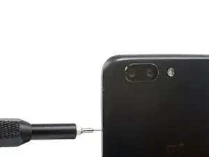
    • Insert a SIM card eject tool, bit, or a straightened paperclip into the small hole below the SIM card tray, located near the rear cameras on the edge of the phone.

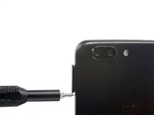
    • Press firmly to eject the tray.

    • During reassembly, be sure to properly orient the SIM tray you you insert it.

  2. TBQWhWKy1QEZvuXb
    • Remove the two 2.6 mm T2 screws straddling the USB-C port on the bottom edge of the phone.

    What are the reference of the screws ? They are missing in the one I bought !

    Yôken Asakura -

    Hi Yôken,

    They help hold the back cover on. Most of the time, the clips are enough to hold the phone together.

    Arthur Shi -

    Just FYI, for whatever reason my brand new OnePlus 5 had 0,8 mm stars screws instead of T2 Torx.

    strixaluco -

    Same here, T2 doesn’t fit the screws on my Oneplus 5. More like T1’s

    Shaze An -

    Definitely T2 for me. Do watch out during assembly. I have a feeling that it’s easy to strip these.

    Juno Grégoire -

    T2 for me too. It was missing in my kit and iFixit sent it later when I asked them about it.

    Gitanshu Sardana -

  3. P3gkh4u1CW6BvaUT
    P3gkh4u1CW6BvaUT
    HZ2oq3334XBwxOSd
    Z2kNTKjf2Hn4xfhd
    • There is a high risk of damaging the display panel if this opening procedure is improperly followed.

    • The following four steps show how to pry the rear case from the plastic frame. Read through the steps first before attempting the procedure.

    • There are two different seams between the body and the screen of the phone:

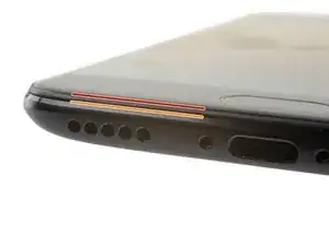
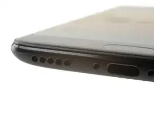
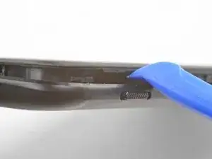
    • Display panel seam: This seam is part of the display assembly. Do not pry at this seam, or you will separate and damage the display panel.

    • Frame seam: This is where the plastic frame meets the back cover. Only pry at this seam.

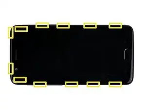
    • There are twelve clips that hold the frame against the rear case. Be aware of their location as you pry the back cover off in the following steps.

  4. etwdJRYqsaaDhSnk
    etwdJRYqsaaDhSnk
    KfBDXKWXddFXRNSI
    • As you work, try not to accidentally power on the phone. If you do, turn the phone off before resuming disassembly.

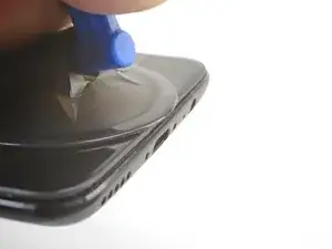
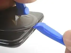
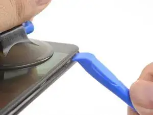
    • Place a suction cup near the bottom edge of the display.

    • Pull on the suction cup with strong steady force.

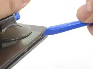
    • Press the edge of an opening tool straight into the frame seam near the suction cup until the edge wedges between the plastic frame and the back cover's lip.

    • Due to tight tolerances, this will take substantial force. Using a new opening tool with an unmarred edge will help with this step.

    I found pushing open the frame seam at the corner works better than pushing from the middle like it is shown in the pictures

    Mark -

    I found the suction cup to be more of a hindrance and kept hitting the power button, making it necessary to stop and turn the phone off again. I watched a youtube video where the person didn't use a suction cup at all and decided to try that. I also found that a guitar pick type spudger worked far better than the one shown in the picture. If you're having trouble getting it started, I suggest trying those two things.

    Brett Gersekowski -

  5. G2EuFKReywNVunqY
    G2EuFKReywNVunqY
    2EGqswv53ufVdUop
    KCOec3LgxFrVKBPp
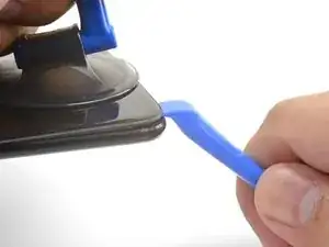
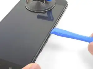
    • Once the opening tool's edge is wedged in position, carefully slide the tool along the bottom edge of the phone.

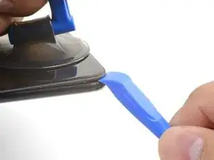
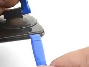
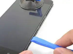
    • Carefully guide the opening tool around the left corner of the phone while keeping the tool's edge within the seam.

    This was extremely difficult & took a lot of force. I needed a thin flat metal spudger and wrecked a couple of plastic ones in the process. I left a few scratches along the join in the process. It would be easier if I had something to hold the phone, in my hand I kept turning it on by accident.

    David Hoffman -

    what was the metal spudger did you use? I am having trouble as well. I cannot seem to pry the back cover and it feels like it is shut tightly, there are no crevices I can pry into. What was your strategy may I ask?

    Azure Shoti -

    At first, I slightly opened the body with a plastic tool, but it was not enough to actually open the back cover. Then I used a thin metal screwdriver for this. It was difficult but nothing special. Just be sure that you are opening the correct seam between the body and the screen and don’t make sudden moves. I bent nothing, everything came back in place when reassembled.

    ivan -

    Same as David here: the plastic opening tools/guitar picks were doing nothing (not even creating the first "crack") . In the end I managed to open it using Jimmy (the metal knife/spudger), but not without scratching the whole metal cover.

    Nessuno Nessuno -

  6. rUcRRH2p6evfJ4RY
    rUcRRH2p6evfJ4RY
    DLUeRvMBGB6N1HCZ
    • Lever the opening tool to release the first clip from the frame.

  7. 1IHQhNpSXtTNfbdc
    1IHQhNpSXtTNfbdc
    GdYPl1KTgPXLaenS
    23SiWCmSwCvYEIZ5
    • Continue sliding the opening tool along the long edge, releasing the clips along the way.

    • The last clip in the top-left corner near the front-facing camera is recessed and can be difficult to release. Take your time and use the flat end of a spudger or an opening pick to help.

    If you have difficulties with the last clip on the upper left. Try to go round the other side (right side), beginning at the bottom. This worked very well for me after having some difficulties with the clip near the front camera.

    Sebastian -

  8. 6ViL6JCT2JdJC2mB
    • With the bottom and left edge of the phone freed, gently wiggle the frame to release the top and right edge clips.

    • The frame is still connected to the back cover by a long flex cable. Do not remove the back cover.

    • During reassembly, pause here to test your phone's functionality before securing the back cover.

    • To reinstall the back cover:

    • Align the top edge of the frame to the back cover and ensure that the top clips slip into place.

    • Squeeze along the long edges of the phone to snap the remaining clips into place.

    Reinstalling the back cover stumped me for a second… If you’re struggling with aligning the top edge of the frame, remember that the camera is going to look off/pointed a bit too low until you actually clip the frame back in.

    Really stupid but it was the only thing that tripped me up in this guide.

    Roger -

  9. s3eTthVrvSeQdHbg
    s3eTthVrvSeQdHbg
    OpemIa6DLGUeoyEj
    AwYBQfaKDAKrtFmE
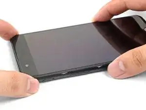
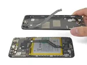
    • With all the clips released, flip the phone over so that the display is face-down.

    • Swing the back cover around and rest it on top of the exposed frame.

    • Be careful not to stress the flex cable connecting the back cover and the frame.

  10. pfyQGq3RaDESTTM2
    pfyQGq3RaDESTTM2
    rTFqnIgaPC1VYRKZ
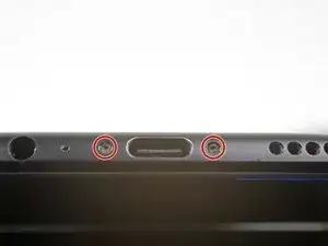
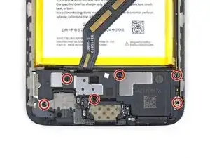
    • Remove the 2.6 mm Phillips screw holding the cable bracket above the battery in place.

    • Lift up and remove the cable bracket.

    • To reinstall the bracket, position one end into place, and bend the bracket slightly to spring the other end into place.

  11. RJeEHKqpOLtBPtO6
    RJeEHKqpOLtBPtO6
    EANPufBOY5oCwAai
    • Use the point of a spudger to pry up and disconnect the back cover flex cable from its socket.

    • To re-attach press connectors like this one, carefully align and press down on one side until it clicks into place, then repeat on the other side. Do not press down on the middle. If the connector is misaligned, the pins can bend, causing permanent damage.

    If it is damaged permanently is there a solution for it?

    Run River -

    If the flex cable pins are damaged, the flex cable can be replaced.

    If the connecter pins (on the motherboard) are damaged, you might need to do microsoldering (or contact a microsoldering company) to replace the damaged connector.

    Brendan -

  12. CkrFZmYRNbVCqR4i
    • Remove the back cover.

  13. Xbxj4YR6HFSJhTZo
    Xbxj4YR6HFSJhTZo
    NsuNfUZJkyVaCEWg
    • Use the point of a spudger to pry up and disconnect the battery connector from its socket.

  14. hWAKPeA4uPKOHV4n
    • Remove the six 2.6 mm Phillips screws securing the loudspeaker to the frame.

  15. SAq12RkicpY13HQU
    SAq12RkicpY13HQU
    NhLAyY5F5CxkQU3D
    • Insert the flat end of a spudger into the corner of the loudspeaker assembly and pry slightly, loosening the loudspeaker from its recess.

  16. gwWsgoh41HeHMTqc
    • Remove the loudspeaker.

    • To reinstall the loudspeaker, align the loudspeaker's bottom edge to the frame, then press the assembly into place.

    • During reinstallation, make sure that the display cable connector under the loudspeaker assembly is still securely fastened.

  17. MCZVWKZDidrnpCTl
    MCZVWKZDidrnpCTl
    oEntDs4ETvhnoEDt
    cLG1RDKQldkYWaB3
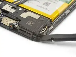
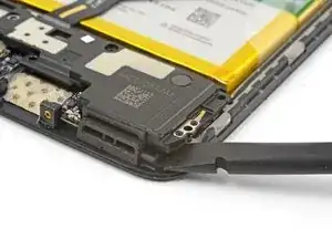
    • Use the point of a spudger to pry up and disconnect the interconnect flex cable from the socket.

    • If you are replacing the battery, bend the interconnect flex cable away from the phone and secure it out of the way with a rubber band or tape.

    What if you’re NOT replacing the battery?

    e nigma -

    This step is used in multiple guides, and not all of them require the cable to be bent away. You can just leave it sitting there, disconnected.

    Arthur Shi -

    This image seems to show the daughterboard removed but there is no corresponding previous step. I see no way to remove the interconnect flex cable without removing the daughterboard. Possibly the volume switch can be removed with the cable still connected but I'm not confident enough to try this so will remove the daughterboard.

    David Hoffman -

    David,

    Thanks for bringing this up. That's indeed a procedural error! I've added the missing steps in the affected guides.

    Arthur Shi -

  18. YMR2tis5L51nDXfo
    • Peel the green pull tab up from the battery.

  19. JN2mfbuNdwYjPda1
    JN2mfbuNdwYjPda1
    soJVkPrnSUoZJrdL
    fI5sOH1e3HCQWiNN
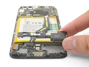
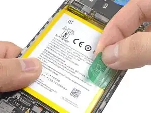
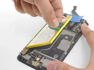
    • Brace the phone frame against the table.

    • Using a strong, steady force, pull the green pull tab upwards until the battery loosens from its recess.

    • If you are having a hard time, apply some high concentration (over 90%) isopropyl alcohol along the battery seam to help weaken the adhesive.

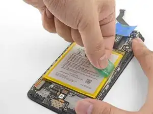
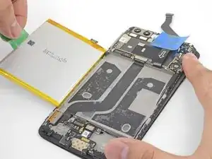
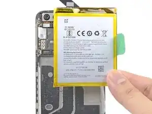
    • Swing the battery completely out of its recess and pull it off of the plastic liner.

  20. 5eKUhLH5srOiBvMD
    • Remove the battery.

    • Do not reuse the battery after it has been removed. Reusing a battery that is bent or otherwise stressed is a potential safety hazard.

    • If your replacement battery did not come with a green pull tab, you can transfer the old tab to the new battery to help with subsequent replacements.

    • While installing a new battery, temporarily connect the battery to the phone to ensure proper battery alignment.

    • If you are installing a battery onto a new screen and digitizer assembly, be sure to peel off the dark blue adhesive liners to expose the battery adhesive for the new battery.

  21. cQc1JkxNDVfVT3am
    cQc1JkxNDVfVT3am
    yZe2h4tPEFHPf1dg
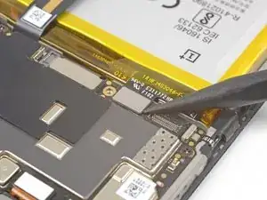
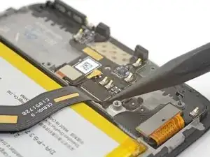
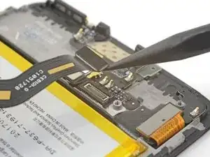
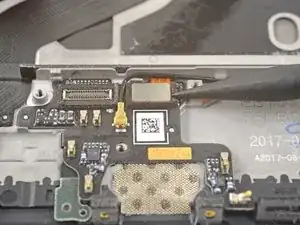
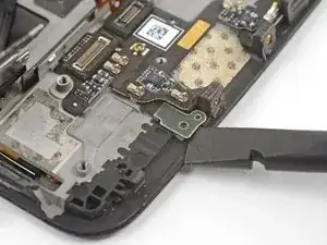
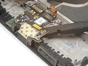
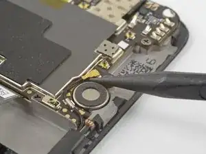
    • Use the point of a spudger the pry up and disconnect the fingerprint scanner connector from its socket on the daughterboard.

  22. n1jNWXD6QZvn5oAT
    n1jNWXD6QZvn5oAT
    WnOvlMQUg1GiUZLv
    2AVcKutAL2y3WJr4
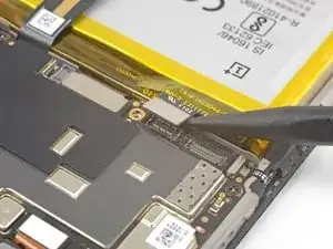
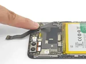
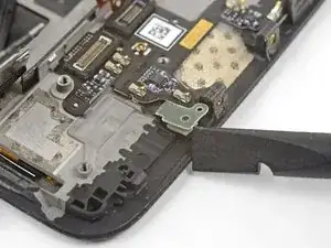
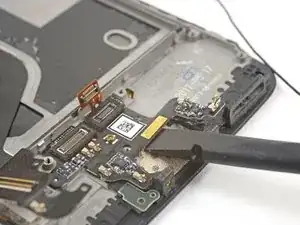
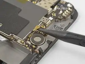
    • Slip the point of a spudger underneath the antenna interconnect cable and pry up to disconnect it from its socket on the daughterboard.

    • De-route the antenna interconnect cable out of the way of the daughterboard.

  23. krnTS6DLNFHJd6kb
    krnTS6DLNFHJd6kb
    eYxnEJUkSpqw6mUe
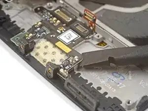
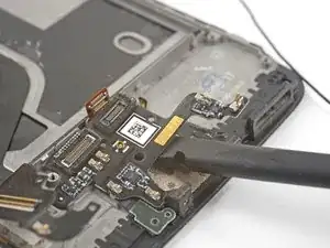
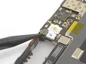
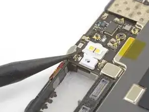
    • Insert the edge of a flat end of the spudger underneath the microphone board and twist slightly to release the board's adhesive.

  24. a4PZbHqngLYnjuTF
    a4PZbHqngLYnjuTF
    gw6SssQ1OpGaxBxU
    UTwLDnNXAINvPSKk
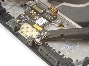
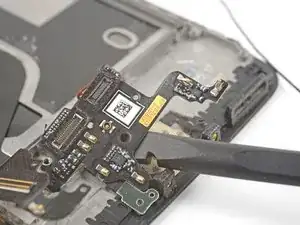
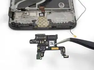
    • Slide the flat end of a spudger or the point of an opening pick underneath the daughterboard near its right edge.

    • Gently pry to loosen the daughterboard from its recess.

    • If the daughterboard begins to bend significantly, stop and pry from a different angle.

  25. EVOCJV5THJccdFqR
    EVOCJV5THJccdFqR
    qnGrYTleSAyergsI
    1yYaomweRUnBWR13
    • Insert the flat end of a spudger underneath the daughterboard, this time approaching it from the bottom.

    • Twist and slide the spudger slightly to release the daughterboard from its recess.

  26. mmvPw5yjV2FcbMJs
  27. U1EAJbnplVEtTKUM
    U1EAJbnplVEtTKUM
    Zc3kOMpXyvhY65Td
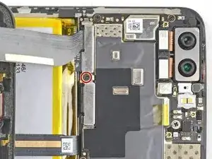
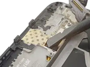
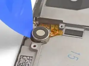
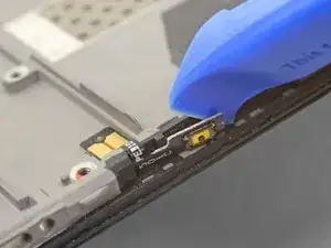
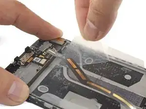
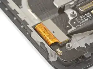
    • Slide the flat end of a spudger underneath the tape covering the fingerprint scanner.

    • Lift up to pry and remove the tape.

    • You will most likely not be able to reuse the tape during reinstallation. Replace it with a piece of electrical tape.

    Hello! Does this silicone tape have the same thickness as the mesh that will be removed during disassembly? Do you have a mesh like that available or do you know a place to purchase it online?? Thanks

    Alexandros Kettenis -

  28. wJLLfiriTvnUQcFX
    wJLLfiriTvnUQcFX
    AwwKwD5jfLTlUr5I
    • If you are planning to reuse the fingerprint scanner, be extremely careful pulling the flex cable up. It is very delicate and prone to breaking.

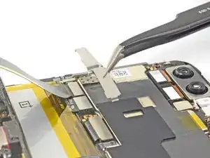
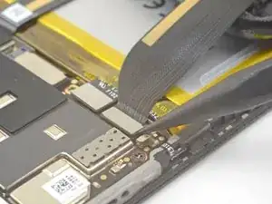
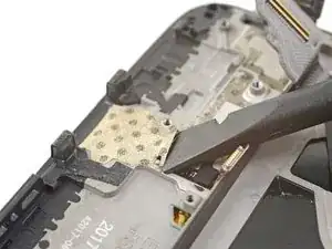
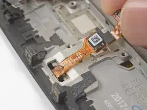
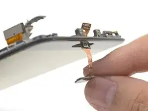
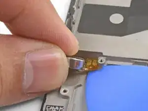
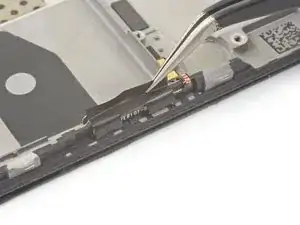
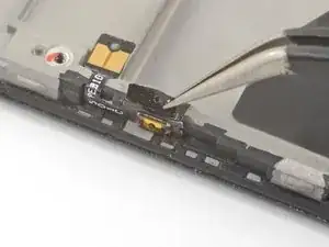
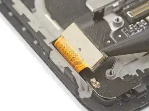
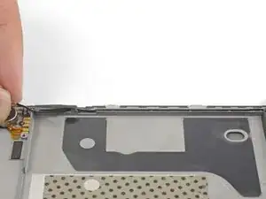
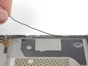
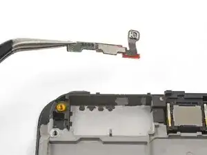
    • Use your finger to gently lift up the connector end of the fingerprint scanner. Pull upwards slowly. Do not pull directly away from the fingerprint scanner.

    • Keep pulling upwards until the fingerprint scanner cable is freed from its recess.

    I couldn’t release this by pulling upwards as shown. Maybe I wasn’t brave enough & could have pulled harder. I used a fine pointed end of a scalpel blade under the left side where the QR code is & that, while pulling gently, did the trick.

    David Hoffman -

  29. wyUqQvkNg6jkIW6T
    wyUqQvkNg6jkIW6T
    4ebJvGAvFamWCxg2
    jlItl2WLL6fpPYDB
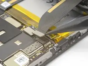
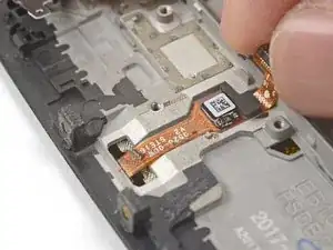
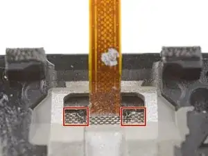
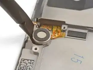
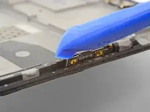
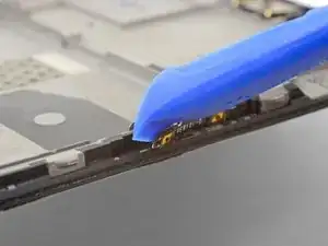
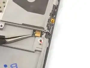
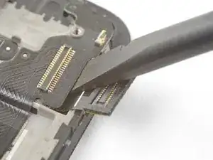
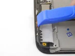
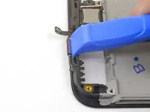
    • Insert the point of a spudger into the marked areas on either side of the flex cable, and push until the fingerprint scanner is loosened from its recess.

    • Do not apply pressure directly onto the delicate flex cable.

    • If the fingerprint scanner is not coming loose, make sure you are pressing the spudger's point against the backside of the scanner as indicated in the first image, and not the metal plate below it.

  30. kRTbelMqCEEYWSli
    kRTbelMqCEEYWSli
    BBcayJRmYOwVWjaH
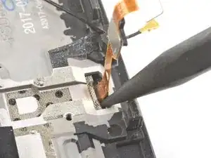
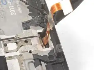
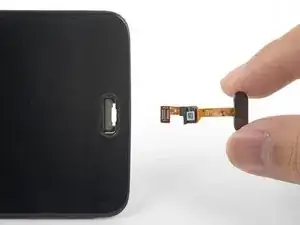
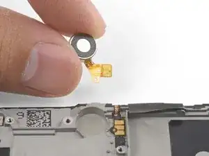
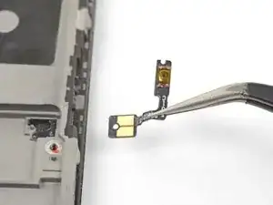
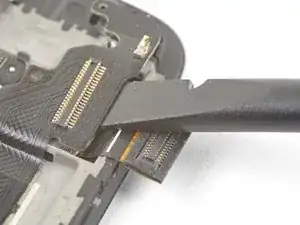
    • Once the fingerprint scanner is loosened from its recess, carefully thread its flex cable through the cutout, out of the front of the display.

    • Remove the fingerprint scanner.

    • If you are installing the fingerprint scanner onto a replacement frame, be sure to peel off the blue adhesive liner for the fingerprint scanner before sticking it in place.

    My replacement fingerprint scanner did not come with any adhesive to hold it in place and it floated above the surface of the phone. I used a tiny amount of very carefully applied Gorilla contact adhesive which worked but will be a pain to remove next time.

    David Hoffman -

  31. yKXVoMtJiIFeWKMl
    yKXVoMtJiIFeWKMl
    IS1d1uiCoPtWoTqK
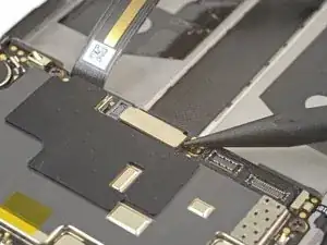
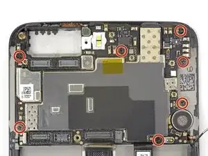
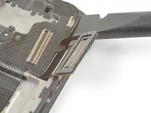
    • Use the point of a spudger to pry up and disconnect the display interconnect cable from its socket near the bottom edge of the motherboard.

    Hallo, hier scheint der Schritt zu fehlen, in dem das Kameramodul entfernt wird.

    Norman Rieß -

    Hello Norman,

    You do not need to remove the camera module for procedure.

    Arthur Shi -

    Hi Arthur,

    You do need to remove the camera module, it’s in the photographs above, but not from step 33 onwards. It needs removing in order to remove the motherboard in steps 34 and 35.

    Alex Thornicroft -

    Hi Alex! Thanks for the feedback! Can you relay which replacement guide you found the missing steps in? That would help me very much!

    Arthur Shi -

    There are no steps 33, 34, 35 in this guide so the above comments must be from some other guide. With this phone I just lifted out the motherboard, carrying the camera with it. It went back the same way - but be careful not to trap the connector cable at the front under it.

    David Hoffman -

  32. kkBt4JZ2ylS3SAPX
    kkBt4JZ2ylS3SAPX
    BHwQ6nLQPvtI1EQK
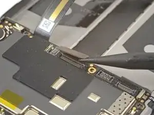
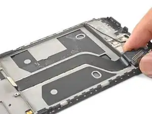
    • Slide the point of a spudger underneath the antenna interconnect cable that is connected to the motherboard above the vibration motor.

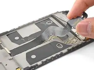
    • Pry up to disconnect the cable from its socket.

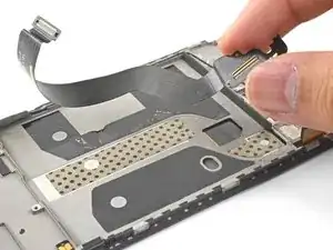
    • De-route the cable out of its motherboard grounding clip and move it out of the way.

    Be attentive when reassembling if your unit doesn’t have a tape, which keeps antenna interconnect cable in place — I’ve accidentally got it squeezed with back cover.

    strixaluco -

  33. AhSMY5mBhuxd3hga
    AhSMY5mBhuxd3hga
    OZbNTaJCGn5WZTFm
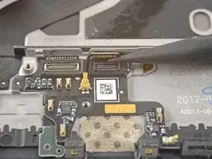
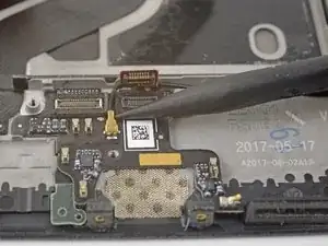
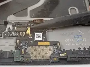
    • Slide the point of a spudger under the small square antenna connector connected to the motherboard near the top edge.

    • Pry up to disconnect the antenna connector from its socket.

    camera step seem to be missing

    Juan de la Cruz Calvo Pozo -

    The cameras should be removed in step 14.

    Arthur Shi -

  34. GNP4m5Jr3apk1c1W
    • Remove the following seven 2.6 mm Phillips screws securing the motherboard:

    • Some screws may be hidden under stickers. Remove the stickers to access the screws.

  35. KvQRsVtAuIU6eCah
    KvQRsVtAuIU6eCah
    iuWxAIZaXxPNBUTv
    vDOdpjSVkhGJNOXN
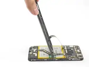
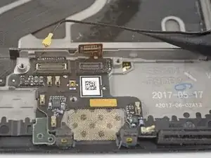
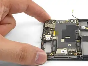
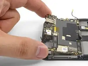
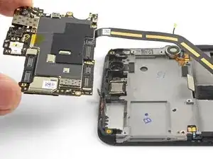
    • Use your fingers to lift up the top edge of the motherboard.

    • Lift the motherboard out of its recess and remove it.

    The camera lens did not come up with the board.

    e nigma -

    Yup the cable with connector is glued to the frame. I removed the tape attaching the camera to the board, then removed the camera connector by gently pushing from the side. It does not seem to be glued.

    Jason -

    The previous steps have not removed the camera although the pictures show it has been removed. I found that I could carefully lift away the motherboard with the camera attached.

    David Hoffman -

    When replacing the motherboard take care not to trap the small square antenna connector under the top edge.

    David Hoffman -

  36. DMxPMAKOoX4EvmhY
    DMxPMAKOoX4EvmhY
    AcIhpAqpxQ5BHRQL
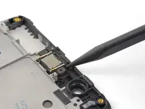
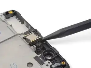
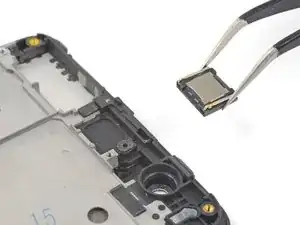
    • Insert the point of a spudger under the top right corner of the earpiece module and pry up, loosening the module from its recess.

  37. ZoWieZQJQI22U6wj
    • Remove the earpiece module.

    • During reinstallation, be sure that the earpiece module is properly oriented such that the gold contacts face downwards.

    • If you are transferring the earpiece module to a replacement frame, be sure to peel and remove the white adhesive liner before pressing the earpiece module into place.

  38. UL2CeHtNVaJwuuZj
    UL2CeHtNVaJwuuZj
    kPJCccIISqTKJ5TQ
    F2IoaRMnRUfDMUoN
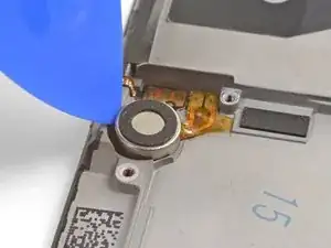
    • Wedge the point of an opening pick between the vibration motor and the frame and push downward to loosen the vibration motor from its recess.

    • Once the vibration motor is slightly loosened, you can wedge the flat end of a spudger between the motor and the frame to help free it from its recess.

  39. jT34O3RlNYHLrgwc
    jT34O3RlNYHLrgwc
    byjYZi1Wv3JnKajs
    • Slide the point of an opening pick underneath the vibration motor's flex pad and gently pry it off of the frame.

    • Remove the vibration motor.

    The pads were stuck to the frame. The pads eventually broke off the cable. Be careful. Maybe use a heatgun or hairdryer to loosed the adhesive.

    Shannon -

    I found it easier to do the next step first. Without the volume connectors, this gave me a better angle to get the motor connectors off the adhesive.

    A. West -

  40. W1WG2INRniZqyknN
    W1WG2INRniZqyknN
    JCZ1ORLXrFCEoNAn
    • Try not to tear the black tape pieces in this step so that you can reuse them during re-assembly. If you do tear the tape, replace them with pieces of electrical tape.

    • Use tweezers or the point of a spudger to pry up and remove the black tape covering the volume buttons on the right edge of the phone.

    • Repeat the process with the black tape covering the power button on the left edge of the phone.

  41. hkK26RSFdKHPsCXT
    hkK26RSFdKHPsCXT
    AsJOjGN4Z6U3EGWG
    wO3DZDTVVAe6FoVG
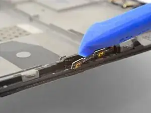
    • Use the edge of an opening tool to gently pry the volume button board away from the frame.

    • If the volume button board begins to bend significantly, stop and pry from a different angle.

    • Continue prying until you loosen the volume button board from the frame.

  42. Mx1NweZX2jF4iGIW
    Mx1NweZX2jF4iGIW
    KERPqMCMtIFd5bMd
    C2EKapnQvVIZLSQL
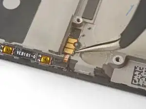
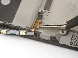
    • Squeeze the tweezer tips together and insert the point underneath the volume button board's contact pad near the top right edge of the frame.

    • Pry upwards to loosen the contact pad from the frame.

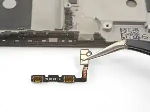
    • Remove the volume buttons.

    • To install the volume button board onto a used frame, cut a small piece of adhesive from the pre-cut adhesive card or a roll of Tesa tape, and use it to stick the volume button board back onto the frame.

    • To install the volume button board onto a new replacement frame, peel the blue liner on the right edge of the frame to expose the adhesive. Then, stick the board onto the edge of the frame.

    Installing a vol button to a used frame I found the existing adhesive (a black sticky rubbery compound) still sticky enough to hold all in place except for the last 2mm of the outer strip with the switches which I fixed with a tiny piece of double sided tape. The tape was not at all adhesive & it's not obvious what it's for. Electric tape doesn't stick to the vol button strip so I used 2 or 3 pin prick size dots of contact adhesive to keep it in place. Fingers crossed!

    David Hoffman -

    This is the only step which mentions using a used board and tesa tape. Is it possible to use tape in the other places adhesive is used?

    Ansi -

  43. EtcfZEWNmDOBABfw
    EtcfZEWNmDOBABfw
    iZVrLJLoHs5qeKfq
    rGuxFCvhlY1rXryG
    • Repeat the previous two steps to remove the power button from the left edge of the frame.

    • If you are transferring the power button onto a replacement frame, peel the blue liner on the left edge of the frame to expose the adhesive. Then, stick the button onto the edge of the frame.

  44. Wlsi4ZjcJAK1TFSM
    • Peel and remove the plastic battery liner from the frame.

    • If your replacement battery did not come with this plastic liner, save it and transfer it to the replacement frame.

  45. Vx6XvvpVmwifgCFP
    Vx6XvvpVmwifgCFP
    oG44JktssLmDjEZy
    • Use the point of a spudger to pry up the display connector from its socket near the bottom left corner of the frame.

  46. 1JKgARmWLCYl5XTS
    1JKgARmWLCYl5XTS
    pkLDanusVA6F2xXS
    OSnTYFgACbT5sH12
    • Insert the flat end of a spudger underneath the display interconnect cable socket, near where it connected with the display connector in the bottom left corner of the frame.

    • Pry upwards and slide the spudger underneath the cable to loosen the cable from the frame.

  47. NSqIWR1JbExJbXBe
    NSqIWR1JbExJbXBe
    bcHRDeA3jtsCCKTS
    RG2gjL6VTjOACZiE
    • Grasp the loosened end of the display interconnect cable with your fingers and pull upwards, releasing the cable from the frame.

    • Remove the display interconnect cable.

    • If you are transferring this onto a replacement frame, peel and remove the blue adhesive liners before sticking the cable in place.

  48. V3ylfRRY6yCBtjkS
    V3ylfRRY6yCBtjkS
    ROx6rhQnGPxAJZGM
    • Use your fingers to lift and de-route the antenna interconnect cable from its groove on the right edge of the frame.

    • Transfer the antenna interconnect cable to the new frame.

  49. pCxQHHvtsFix5xAe
    pCxQHHvtsFix5xAe
    pZ3HPjreDtIkRNuw
    VolIvj1lIuUQeXCx
    • Use the edge of an opening tool to push the back cover antenna connector away from the frame. It is located on the top edge of the frame.

    • Remove the back cover antenna connector.

    • If you are transferring the connector onto a replacement frame, peel the blue liner on the top edge of the replacement frame before sticking the connector onto the edge.

  50. OZw5IjPwTUToXk4o
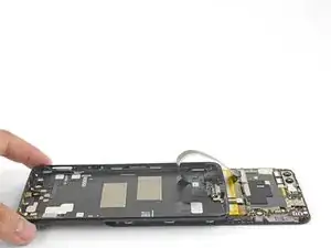
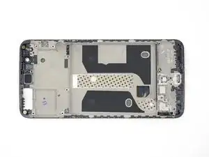
    • The bare screen and digitizer assembly remains.

    • Transfer all of the parts you removed in the previous steps from the old assembly to the new one.

Conclusion

To reassemble your device, follow these instructions in reverse order.

Take your e-waste to an R2 or e-Stewards certified recycler.

Repair didn’t go as planned? Check out our OnePlus 5 Answers Community for troubleshooting help.

Arthur Shi

Member since: 03/01/18

248651 Reputation

17 comments

Nice. But where do you get the replacement part from?

Christos Mantas -

Dear Christos, hope it is not too late, you can check Oneplus 5 screen replacement from Witrigs

Witrigs -

HI . Do I need to buy an original screen and digitizer for my oneplus 5?

I'm from Argentina and on EBAY I do not see ORIGINAL parts

Can someone help me?

Joselo -

Hi Joselo,

You do not need an original, but that is probably the best quality. The original screen is AMOLED. There are also OLED and LCD replacement screens. These will not be as bright as the original AMOLED panel.

Arthur Shi -

Hi, I need to know if this screen is like the original (Amoled) or not, and approximately how long it takes to send by mail to Miami Florida. Thank you OnePlus 5 Screen

Joselo -

Hi Joselo, that Screen and Digitizer Assembly is indeed an AMOLED screen and digitizer.

As for the shipping question: In order to determine shipping estimates, costs, and methods, you will need to enter your shipping address at checkout as this may vary based on the specific address.

If you ever have any questions, feel free to contact our iFixit Customer Support. We are always here to assist if you need anything. :)

Cooper -

Wow, this repair looks hard. I’d rather buy a new phone than attempt this.

UnicornsOnLSD -

Don’t blame you; the time commitment is hard to justify. However, I had a few hours to spare and took it slow: now I have a backup device from a (my first) phone repair :)

Andrew Chen -

manual is very clear, successfully replaced the screen this weekend. difficulty is not too bad

Sven Herkhof -

DO NOT TRY TO OPEN THE PHONE. Its a !&&* to repair this phone yourself. I opened it and could not epair this phone. Everything is glued and the buttonconnectors are not designed to be replaceble.

CAUTION and do not repair.

momo -

Thanks for the guide, made me able to change my own screen for real cheap!

Martin Brattensborg -

U forgot the front camera :)

Otherwise great guide!

The contacts for the vibration motor were hard to get off!

Jason -

I left the front camera attached to the motherboard when I removed the board, but you can remove it separately.

The vibration contacts are pretty heavily glued in! They have to—otherwise, the motor will shake loose :)

Arthur Shi -

Just used this guide, managed to get all the parts off my old phone but have noticed on the new frame there is not any black sticky for the parts to stick onto, it's just bare metal where they're supposed to adhere. Can anyone enlighten me?? Can I buy this double sided black tape? Is Tesa tape a good replacement? I'm assuming things will short out if I try to stick them into the bare metal frame?

Rich -

Hi Rich,

Tesa tape is a good option! Depending on what you are sticking, you may only need the Tesa adhesive card. For smaller parts such as the side buttons, double-sided tape will suffice.

Arthur Shi -

Nice tutorial. Everything works now after switching the screen. Took about 3h to someone with experience, but the steps are well documented.

The screen replacement from ifixit is not the same quality as the original (particularly the glass is very fragile); still, it's very nice to have access to spare parts and avoid buying a whole new phone!

adj -

Solid guide! Pretty intensive repair; only difficulty was to get a new piece of electrical tape to cover the buttons: ended up neglecting to replace that and just using them as is (with greater sensitivity).

Andrew Chen -