Introduction

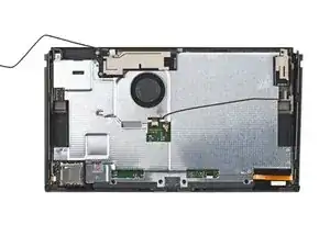
Use this guide to replace the screen OLED assembly in your Nintendo Switch OLED.

The assembly includes the frame with the OLED panel and speakers attached to it. If you're replacing the OLED panel by itself, follow this guide instead.

For your safety, discharge the battery below 25% before disassembling your Switch. This reduces the risk of fire if the battery is accidentally damaged during the repair. If your battery is swollen, take appropriate precautions.

The Switch OLED uses JIS screws, but you can use a Phillips screwdriver in a pinch. Be very careful not to strip the screws. iFixit's Phillips bits are designed to be cross-compatible with JIS-style screws.

Note: When you remove the shield plate, you’ll need to replace the thermal compound between the plate and the heatsink. Since normal thermal paste isn’t designed to bridge large gaps, the closest replacement is K5 Pro viscous thermal paste. You will, however, need regular replacement thermal paste when replacing the heat sink.

  1. Aqkr2qcpW2EMRoth
    Aqkr2qcpW2EMRoth
    jjMbZnUwELeWEVim
    QZwg2fkraMcQnqBH
    • Before you begin this repair, make sure the device is completely powered off.

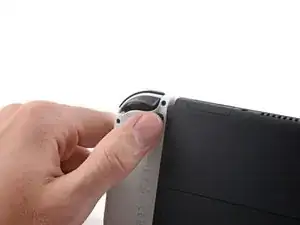
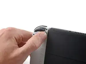
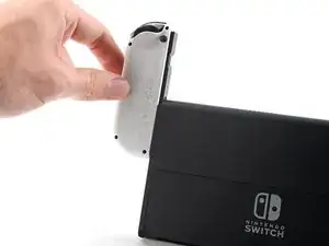
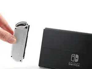
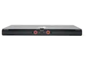
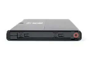
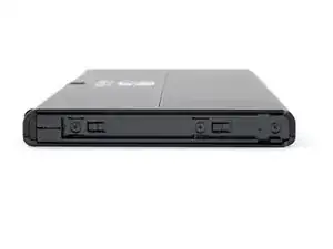
    • Press and hold down the small round button on the back of the Joy Con controller.

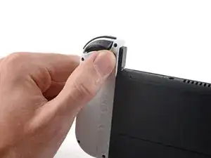
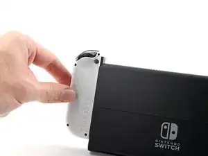
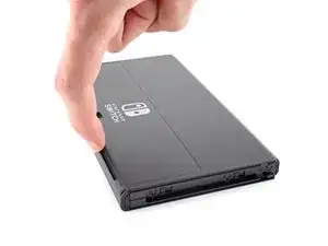
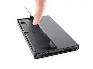
    • While you hold down the button, slide the controller upward.

  2. TpnHGZP1vnaRNl1l
    TpnHGZP1vnaRNl1l
    ohHBvxtofSySZRqx
    MyMBxFvHAHUJa5Mb
    • Continue sliding the Joy Con upward until it's completely removed from the console.

    • Repeat this same process for the other Joy Con.

  3. GUyCUqLYIkbtu1cL
    GUyCUqLYIkbtu1cL
    pbRrj3ADA6YBcIij
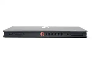
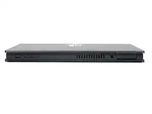
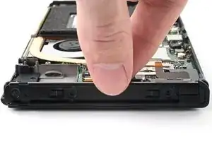
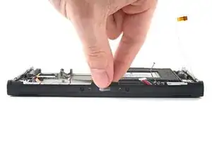
    • Use a Phillips driver, or a JIS driver, to remove the 2 mm-long screw securing the top of the rear case to the frame.

    • To prevent these tight screws from stripping, apply firm downward force, work slowly, and try another JIS or Phillips driver if the screws won't come out.

  4. 1VdcuiWFJxrZADDI
    1VdcuiWFJxrZADDI
    BS1xpadlFjbhrNDL
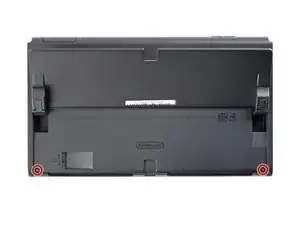
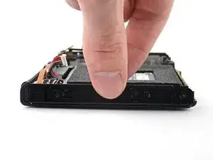
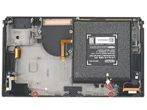
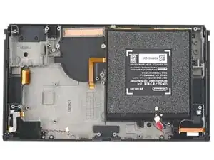
    • Use a Phillips driver to remove the two 2 mm-long screws securing the bottom of the rear case to the frame.

  5. dkQ6QTfPeKCjlwgZ
    dkQ6QTfPeKCjlwgZ
    4UOJFFNNbw4D2CIh
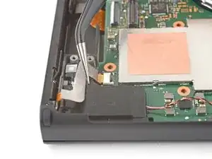
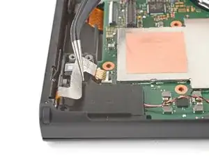
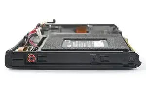
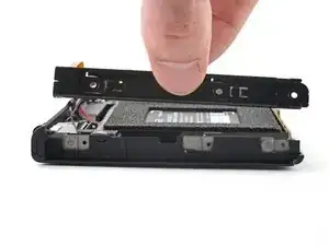
    • Use a Phillips driver to remove the 3.8 mm screw securing the right Joy-Con sensor rail to the rear case.

    • To prevent these tight screws from stripping, apply firm downward force, work slowly and try another JIS 000 or PH 000 driver if the screws won't come out.

  6. 3AsKZQq325jJThdd
    3AsKZQq325jJThdd
    MtCLPPHRy4mHtAmL
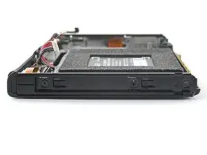
    • Use a Phillips driver to remove the 3.8 mm screw securing the left Joy-Con sensor rail to the rear case.

  7. sNJbmOTjRKA5XDSL
    sNJbmOTjRKA5XDSL
    Q4bPLTJRaXLFB2gV
    • Use your finger to flip up the kickstand on the back of the device.

    • If there's a microSD card in the microSD card slot, remove it now before you continue to the next step.

  8. SXpL4PMsKNHZMplU
    SXpL4PMsKNHZMplU
    jKt41kIGlE2BeD12
    • Use a Y00 screwdriver to remove the two 4.3 mm screws securing the rear case to the frame.

    Before the next step remove any game cards in the console

    Zach -

  9. GnRPlyTSRwEETkRr
    GnRPlyTSRwEETkRr
    t1xAVOyNcIPWdOZs
    Gqe2XivWAcVrDipk
    • Lift the rear case up from the top of the device and remove it.

    • If you're having trouble removing the case, use an opening pick to pry up the plastic clips.

    Just a heads up that, even after removing the screws, the rear plate is still heavily clipped in place. I recommend using an opening pick or opening tool to carefully pry it up starting at the top and working your way down the sides. Once you get to the bottom, the speaker grilles are a little tricky. They're attached to the rear plate, but they can get stuck easily as you're removing the back plate.

    Craig Lloyd -

  10. QavIV6gClTlUkkqV
    QavIV6gClTlUkkqV
    vA6lcFn4kn41HsRV
    • Use the flat end of a spudger to separate a corner of the tape from the shield plate.

    Don't remove the antenna tape or the wires from the tape! The antennae can come off with the large metal shield plate anyways, so why remove them separately?? Extra UNNECESSARY WORK!! Just unscrew the antennae modules themselves, and pop out the antenna wires from the mainboard. Then they will lift with the large metal plate. (Steps 10, 11, 15, 16 are unnecessary, just remove the screws only that hold them down)

    hubbabubbahubbabubba9 -

  11. M1fRXWTIAW6EcDFG
    M1fRXWTIAW6EcDFG
    MGGuU4LsTmoZVHdk
    qwTA5QXA2jjIDmWI
    • Use tweezers, or your fingers, to peel back and remove the tape.

    • Store the tape in a clean space for reinstallation.

  12. yyuZRT2LqOpbEPEn
    yyuZRT2LqOpbEPEn
    oZDi3RVOYGYLnUSs
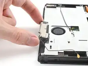
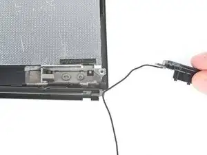
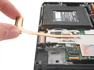
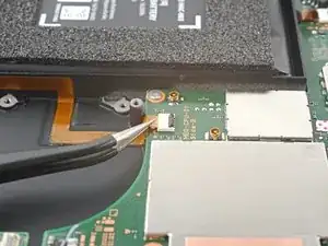
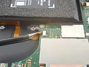
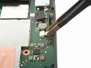
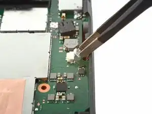
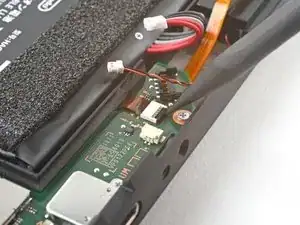
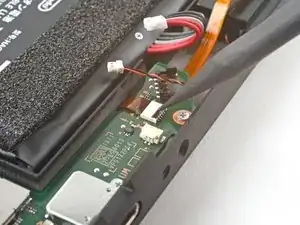
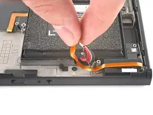
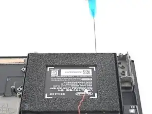
    • Use tweezers, or your fingers, to pull up and disconnect the primary Wi-Fi antenna's coaxial cable.

    • During reassembly, these can be tricky to reconnect. One at a time, hold each connector in place over its socket and press down with the flat end of a spudger. The connector should snap into place.

  13. ZC2XlPmWNxFBFKiu
    ZC2XlPmWNxFBFKiu
    3sRRXxSEppWrTKjh
    1yEQoR1BAAaAQxjx
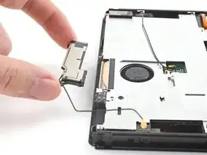
    • Use tweezers, or your fingers, to reroute the primary antenna's coaxial cable out of its slots in the shield plate.

  14. PPZy2IJjVI4JwKDO
    PPZy2IJjVI4JwKDO
    sEZJDkWTXsrZR1Pb
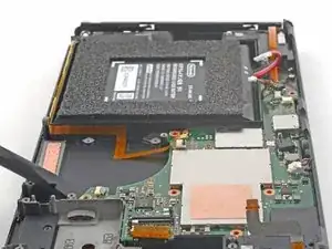
    • Use a Phillips driver to remove the two 4.4 mm screws securing the primary Wi-Fi antenna to the shield plate.

  15. QZPhlTguYNZw4feb
    QZPhlTguYNZw4feb
    JAiRs4LPm5dtXGVg
    1n6Aa4TRSDjGsquo
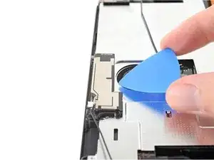
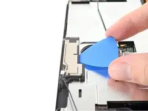
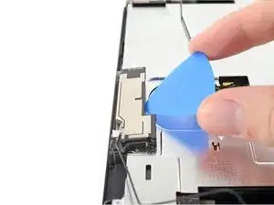
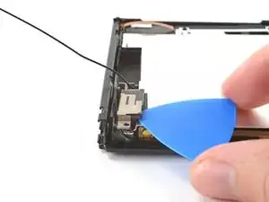
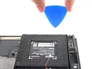
    • Insert an opening pick between the primary Wi-Fi antenna and the shield plate.

    • Pry up with the pick to separate the primary Wi-Fi antenna from the shield plate.

  16. wIHWtjQf1RRWoZEr
    wIHWtjQf1RRWoZEr
    WgkUx3NolkLqDPXy
    • Remove the primary Wi-Fi antenna.

  17. QUV5uuQ5vJkWXYKQ
    QUV5uuQ5vJkWXYKQ
    CqmCcNbHIqwPZaaK
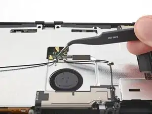
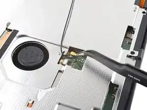
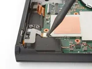
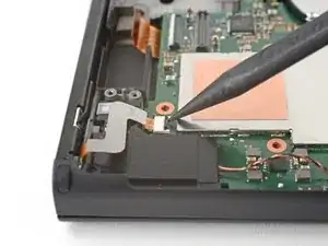
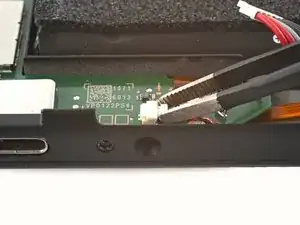
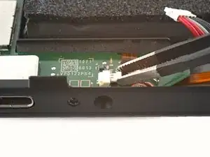
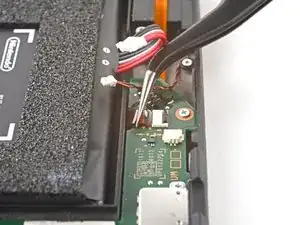
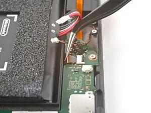
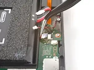
    • Use tweezers, or your fingers, to pull up and disconnect the secondary Wi-Fi antenna's coaxial cable.

  18. ExeA3XTwNbOibDgH
    ExeA3XTwNbOibDgH
    shBJnmBrOVSFFLSK
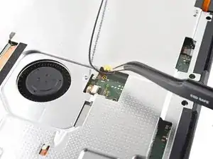
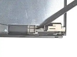
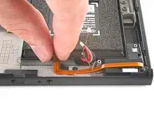
    • Use the point of a spudger to reroute the secondary Wi-Fi antenna's coaxial cable from its slot in the frame.

  19. NE3WlThRJYq45CYb
    NE3WlThRJYq45CYb
    VjESxycEIuQHqOdO
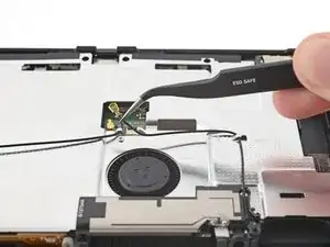
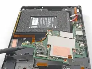
    • Use a Phillips driver to remove the 4.4 mm screw securing the secondary Wi-Fi antenna to the shield plate.

  20. D23SFKabARYvRHxO
    D23SFKabARYvRHxO
    XWlvgxY6hNNvPLb4
    OWL6gRmWQSOM2yYI
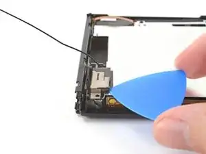
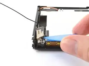
    • Insert an opening pick between the secondary Wi-Fi antenna and the shield plate.

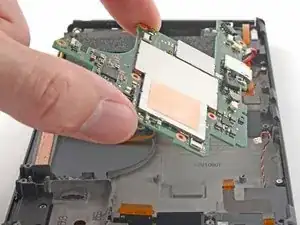
    • Pry up with the pick to separate the secondary Wi-Fi antenna from the shield plate.

    • Don't attempt to completely remove the antenna yet, as its coaxial cable is still routed through the frame.

  21. HT3XVLvJ5dpfsdKq
    HT3XVLvJ5dpfsdKq
    LoDATWQNrWEBXp6V
    QbTXVFUfo5HLbBPS
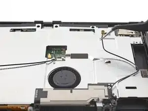
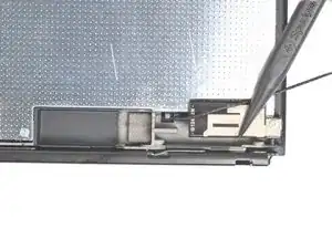
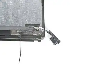
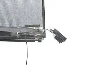
    • Use the point of a spudger to reroute the secondary Wi-Fi antenna's coaxial cable out of its slot in the frame.

    • Remove the secondary Wi-Fi antenna.

  22. ZyROaEH3HFYaTlZm
    ZyROaEH3HFYaTlZm
    iitvpFqoiKbmVwK4
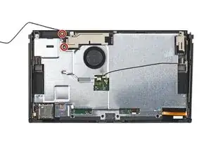
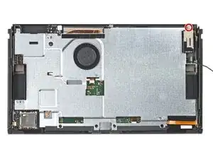
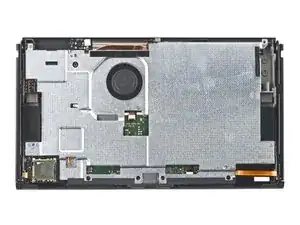
    • Use a Phillips driver to remove the six 4.4 mm screws securing the shield plate to the frame.

  23. Ugd4ewSuVT6QmFAZ
    Ugd4ewSuVT6QmFAZ
    q1Zv4nxLNGGb1Zax
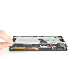
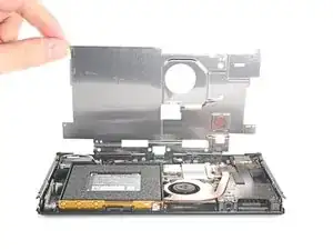
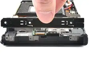
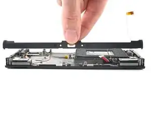
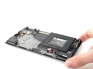
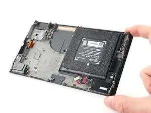
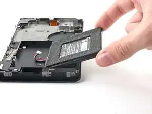
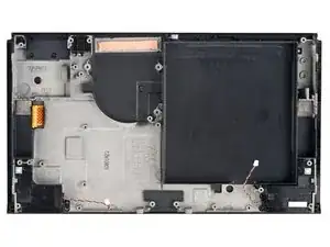
    • Use your fingers to lift the top of the shield plate up and away from the frame.

    • You may feel a bit of resistance. This is normal, since the shield plate is slightly bonded to the heat sink with thermal paste.

    • Remove the shield plate.

    • A thick pink thermal compound bridges the gap between the shield plate and the copper heat sink underneath. Whenever the shield plate is removed, refer to our thermal paste guide to remove the old thermal compound and replace it with an appropriate compound, such as K5 Pro, during reassembly.

  24. YaFdfx1uGjBPFXOm
    YaFdfx1uGjBPFXOm
    SdfdTVfZAgDW3HvE
    • Use the point of a spudger to pry up and disconnect the battery.

  25. DkOnVTElqbUfQDEQ
    DkOnVTElqbUfQDEQ
    hlikDFQ4MScJkxE5
    vXfcOe1BbOaKv1dS
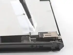
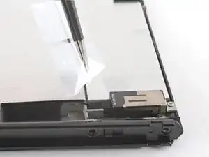
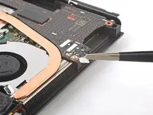
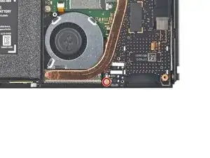
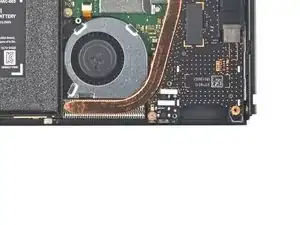
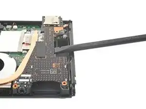
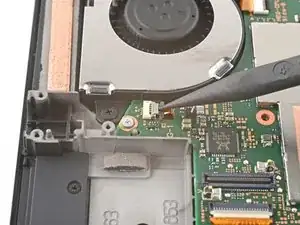
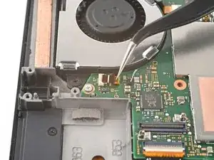
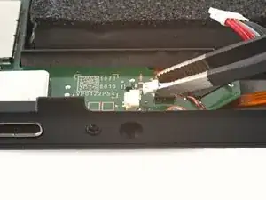
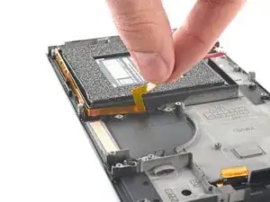
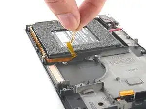
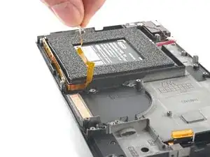
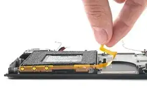
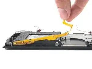
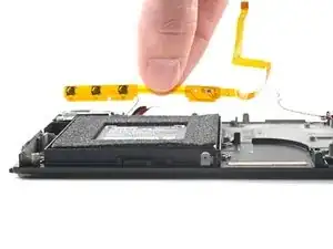
    • Use tweezers, or your fingers, to remove the piece of tape obscuring the daughterboard's screw.

  26. QVfKUbxRdjGWWXEd
    QVfKUbxRdjGWWXEd
    ymHmj4rMrqoVuxoR
    • Use a Phillips driver to remove the 4 mm screw securing the daughterboard to the frame.

  27. 3hZmOMgsQZcMN532
    3hZmOMgsQZcMN532
    ZUNlOfCCVAMo2QIg
    OF1XG1WLomMdBuDP
    • The bottom of the daughterboard is connected to the motherboard via a press connector.

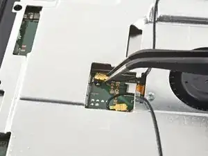
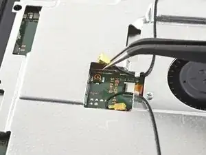
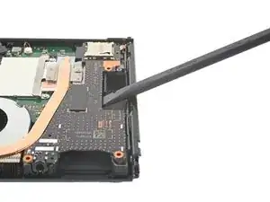
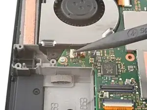
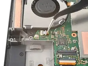
    • Insert a spudger between the edge of the daughterboard and the motherboard.

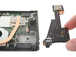
    • Pry up with the spudger to disconnect the press connector and separate the daughterboard from the frame.

    • Remove the daughterboard.

    • To re-attach press connectors like this one, carefully align and press down on one side until it clicks into place, then repeat on the other side. Do not press down on the middle. If the connector is misaligned, the pins can bend, causing permanent damage.

  28. IJDC5PBl5lORUyBb
    IJDC5PBl5lORUyBb
    xjkfeg2gbE1kVrOK
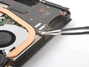
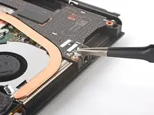
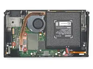
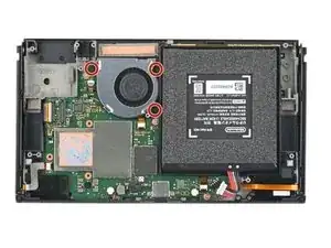
    • Use a Phillips driver to remove the three 3 mm screws securing the heat sink to the motherboard.

  29. p3BLAl1qeKBDdvpD
    p3BLAl1qeKBDdvpD
    VrdTIc3RFRoHtttR
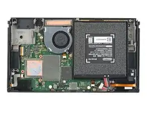
    • Insert a spudger between the heat sink's bracket and the motherboard.

    • Pry up with the spudger to separate the heat sink from the motherboard.

    • You may feel a bit of resistance. This is normal, since the heat sink is slightly bonded to the CPU with thermal paste.

  30. 3jBJJoqBOlATXAhl
    3jBJJoqBOlATXAhl
    KBVXHSar1qPk1DOD
    H1ece4TicvtWJ2NL
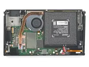
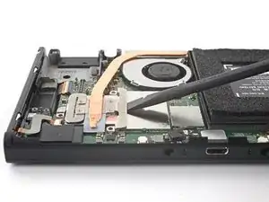
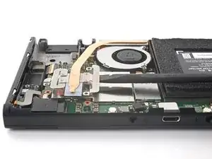
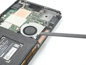
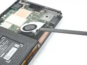
    • Insert a spudger in the gap between the fan and the heat sink.

    • Pry up with the spudger to separate the heat sink from the adhesive beneath it.

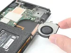
    • Remove the heat sink.

    • Clean off the old thermal paste from the heat sink and CPU using high-concentration (90% or higher) isopropyl alcohol and a microfiber cloth. Apply new thermal paste to the CPU before reassembly.

    The section near the fan is pretty difficult to remove, since it's adhered to the case and there's no good way to get your spudger underneath it, even by inserting it between the fan and the heat sink. Be very gentle and work patiently. It's really easy to bend the heat sink and the fins.

    Craig Lloyd -

  31. MdDOcoRbbmGASTHZ
    MdDOcoRbbmGASTHZ
    B6sSZoRUtECqVAE5
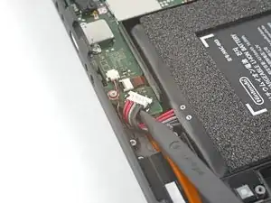
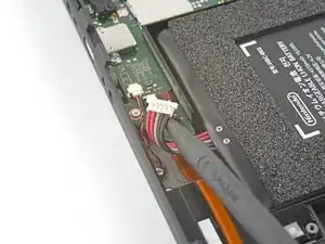
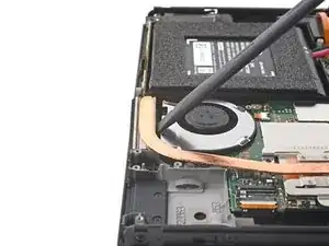
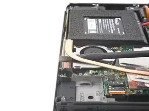
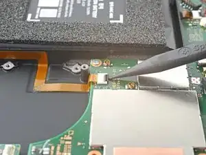
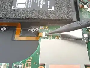
    • Use the tip of a spudger, an opening tool, or your fingernail to flip up the small, hinged locking flap on the fan cable's ZIF connector.

  32. VADSGXbAXqEjcRyN
    VADSGXbAXqEjcRyN
    xGsQLqyo4R44gKtY
    • Use a pair of tweezers to pull the fan cable straight out of its connector on the motherboard.

  33. THQUUGBL5wfLFNX4
    THQUUGBL5wfLFNX4
    X5gmS3kbeSeWliG6
    • Use a Phillips driver to remove the three 3 mm screws securing the fan to the frame.

  34. g1RRC5pMcYgasTFO
    g1RRC5pMcYgasTFO
    uY1L2T3HLMXkWVgN
    RsISfFMKYSGnKtbI
    • Use a spudger to lift the fan out straight out of the frame.

    • Remove the fan.

  35. HaaBPqFGPbB2aXBX
    HaaBPqFGPbB2aXBX
    HCKVuG5xZZecSeTa
    • Use an opening tool, spudger, or your fingernail to flip up the small, hinged locking flap on the power button board's ZIF connector.

  36. mNWgKdl6YJemXHJH
    mNWgKdl6YJemXHJH
    3qsFPdYjQGFTVFJQ
    • Use a pair of tweezers to pull the power button board cable straight out of its connector on the motherboard.

  37. TfJQkIoVPWXJeaOg
    TfJQkIoVPWXJeaOg
    hTNySvJ2oWFAqW4G
    • Use an opening tool, spudger, or your fingernail to flip up the small, hinged locking flap on the right Joy-Con sensor rail's ZIF connector.

  38. aKajNFcoAsPnihkd
    aKajNFcoAsPnihkd
    51Jx4rbxpmFeCJuf
    • Use a pair of tweezers to pull the right Joy-Con sensor rail's cable straight out of its connector on the motherboard.

  39. cHWOGED16mOLNJso
    cHWOGED16mOLNJso
    IV6NnlRObNaUHogG
    • Remove the right Joy-Con sensor rail.

  40. 6kA41MqiuMScwfGH
    6kA41MqiuMScwfGH
    XbdD3kqfQOASTpad
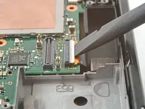
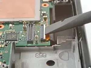
    • Use an opening tool, spudger, or your fingernail to flip up the hinged locking flap on the display's ZIF connector.

  41. kVMPDWwumSLXX46l
    kVMPDWwumSLXX46l
    2k1kbTo3OWmV2OBw
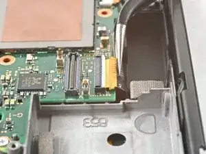
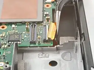
    • Use a pair of tweezers to pull the display cable straight out of its connector on the motherboard.

  42. USUsgJUOBZUoErI4
    USUsgJUOBZUoErI4
    sn6LyvMIRSvchqDX
    htx11DLPBqtdgYIf
    • Use tweezers, or your fingers, to pull the left speaker's JST connector out of its socket.

  43. eRRoGj6rEf2nFtER
    eRRoGj6rEf2nFtER
    GtGeXjqxdweUlICH
    eUeBTeBrcZMAwLYK
    • Use tweezers, or your fingers, to pull the right speaker's JST connector out of its socket.

  44. dQ1WLDldxGQWfCwF
    dQ1WLDldxGQWfCwF
    eqNmDdfLOkZ3ZBQt
    • Use an opening tool, spudger, or your fingernail to flip up the small, hinged locking flap on the right Joy-Con sensor rail's ZIF connector.

  45. oJhLBINiC3sNII5R
    oJhLBINiC3sNII5R
    Py1lCl2CPxrPVJSv
    pRgCwRtTZW252seG
    • Use a pair of tweezers to pull the right Joy-Con sensor rail's cable straight out of its connector on the motherboard.

  46. nIa2LqUFSDFU211P
    nIa2LqUFSDFU211P
    goAy3sDoncBVDHBu
    • Use a Phillips driver to remove the five screws securing the midframe to the frame:

    • Three 3 mm screws

    • Two 4.4 mm screws

  47. dJFsNIITOnwfDWLY
    dJFsNIITOnwfDWLY
    NAxbTliBfouXZBme
    IAkE1c2YhAFGMUAg
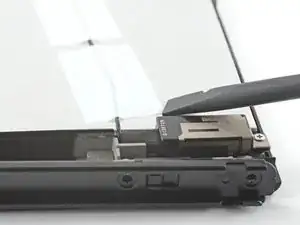
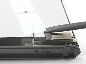
    • Insert a spudger between the motherboard and the frame.

    • Pry up with the spudger to separate the motherboard from the frame.

    • Remove the motherboard.

  48. t4VlYoI1I4mteQHG
    t4VlYoI1I4mteQHG
    hEWdEkZgdcQAO5A2
    • Use your fingers to gently peel back the left Joy-Con sensor rail's cable from the frame.

  49. JWUjCLH6aHYUTW5h
    JWUjCLH6aHYUTW5h
    KmL4JWIiApC3hv3x
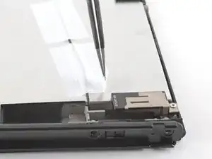
    • Use a Phillips driver to remove the 3.8 mm screw securing the left Joy-Con sensor rail to the frame.

  50. YhxEwWVS2Yjds4tn
    YhxEwWVS2Yjds4tn
    AMQSg1DsxoDjZKBX
    • Remove the left Joy-Con sensor rail.

  51. 6cHagZZAMwTSrZBh
    6cHagZZAMwTSrZBh
    Io3h2InjdWcrbfsf
    • Use a Phillips driver to remove the two 3 mm screws securing the bottom rail to the frame.

    good instructions but my bottom rail came without rubber feet which I found very disappointing. Is there anywhere I could buy a rail with the rubber feet already on their, if not thanks anyways.

    Braddock Baker -

  52. LW2UhwDoARknXqkI
    LW2UhwDoARknXqkI
    16LhjlqHFZTLJvqx
    • Remove the bottom rail.

  53. pRTcTgQK3WrgQwUR
    pRTcTgQK3WrgQwUR
    OSDwMDkdd6qpWDIB
    fxALWYTWKS1sQqwU
    • Use your fingers to gently peel back the power board button's cable from the frame.

  54. ZxZTAckOHntvqWJ5
    ZxZTAckOHntvqWJ5
    qVNVehdLjOPDGWRy
    BZqLHY2YFXIpPoDU
    • Use your fingers to pull the power button board out from its plastic slots in the frame.

    • Remove the power button board.
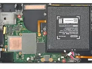
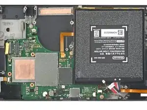
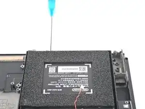
  55. hPFuR1qkUYGLPlZG
    hPFuR1qkUYGLPlZG
    m4iWdg4aGIaS1hZB
  56. dTgx1mATptDrYJrC
    dTgx1mATptDrYJrC
    IyidURYSUMSJhKHX
    • Tilt the top edge of the device upward to allow the isopropyl alcohol to work its way underneath the battery.

    • Hold for 1-2 minutes to allow time for the isopropyl alcohol to weaken the adhesive.

  57. DrjOKTEIeBbl1kJf
    DrjOKTEIeBbl1kJf
    tP6WCDBUwpVZI16U
    Oe4Onyg4AoKkXiAi
    • Insert an opening pick into the gap between the battery and the wall of the battery well.

    • Carefully dig the tip of the opening pick underneath the battery and slide it along the edge to begin slicing the adhesive.

    • Take care not to puncture or bend the battery with your tool—a punctured or bent battery may leak dangerous chemicals or cause a fire.

  58. a6DQdbTnxCCp2ML5
    • Leave the opening pick in place and apply a few more drops of adhesive remover or isopropyl alcohol inside the battery well.

    • Tilt the top edge of the device upward and wait 1-2 minutes for the isopropyl alcohol to weaken the adhesive.

  59. Hq5UEdGLBoovb2iH
    Hq5UEdGLBoovb2iH
    K2iNKMHoDMdkrjff
    • Continue sliding the opening pick deeper along the top edge of the battery, slicing more of the adhesive underneath.

  60. RfWJ3VXpdqZoat5f
    RfWJ3VXpdqZoat5f
    OFFZrkooqRO4Px5M
    fsjHFDw5AISKVKIn
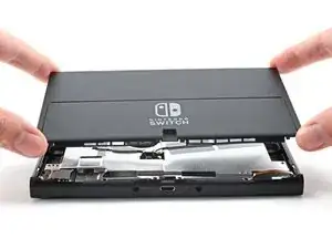
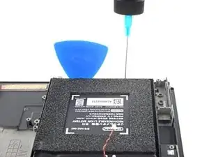
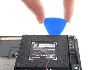
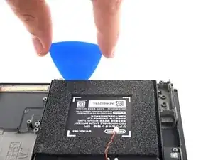
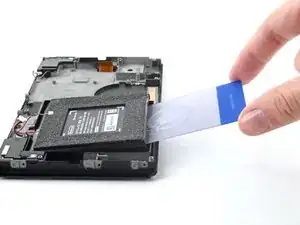
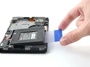
    • Once there's enough room, insert a plastic card underneath the battery and slowly pry the battery up.

    • Apply more isopropyl alcohol if you have difficulty prying.

    • Be careful not to bend the battery as you pry.

  61. ICk5XSeaiEVgpNRX
    ICk5XSeaiEVgpNRX
    1Lg3rSWhcwsTUaJM
    GxddqNcHGxTX4yWg
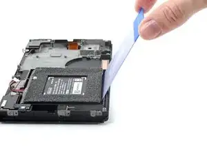
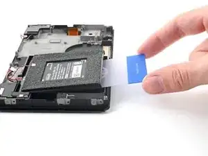
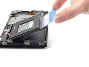
    • Pry up with the plastic card to completely separate the battery's adhesive.

    • Remove the battery.

    • Use adhesive remover or isopropyl alcohol and a microfiber cloth to clean up any remaining adhesive left behind in the battery well before you install the new battery.

    • If your new battery does not come with pre-installed adhesive, follow this guide to install pre-cut adhesive on the bottom of the battery.

    • Do not reuse the battery after it has been removed, as doing so is a potential safety hazard. Replace it with a new battery.

  62. HLDtcZ4j3JxCX2GR
    • You're now left with the Screen OLED Assembly.

Conclusion

To reassemble your device, follow these instructions in reverse order.

For optimal performance, calibrate your newly installed battery after completing this guide.

Compare your new replacement part to the original part—you may need to transfer remaining components or remove adhesive backings from the new part before you install it.

Take your e-waste to an R2 or e-Stewards certified recycler.

Repair didn’t go as planned? Try some basic troubleshooting, or ask our Nintendo Switch OLED Answers community for help.

Alex Diaz-Kokaisl

Member since: 16/01/22

117875 Reputation

0 comments