Introduction
Use this guide to replace the motherboard (with an added right Joy-Con sensor rail removal) in your Nintendo Switch.
This is a prerequisite-only guide! This guide is part of another procedure and is not meant to be used alone.
-
-
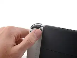
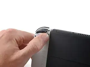
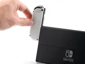
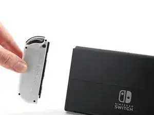
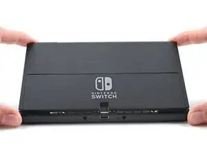
Press and hold down the small round button on the back of the Joy Con controller.
-
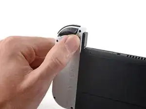
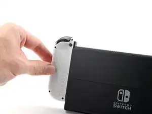
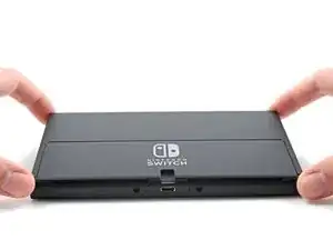
While you hold down the button, slide the controller upward.
-
-
-
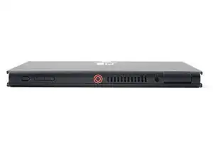
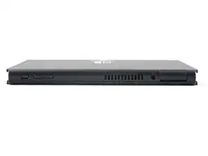
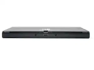
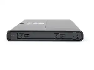
Use a Phillips driver, or a JIS driver, to remove the 2 mm-long screw securing the top of the rear case to the frame.
-
-
-
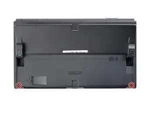
Use a Phillips driver to remove the two 2 mm-long screws securing the bottom of the rear case to the frame.
-
-
-
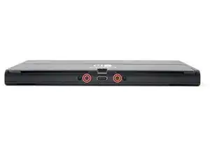
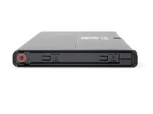
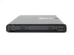
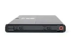
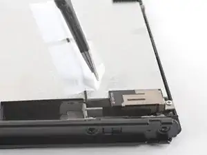
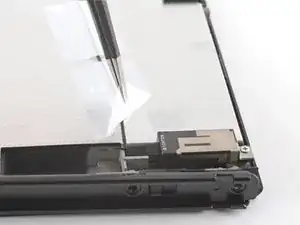
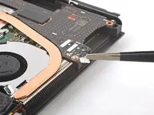
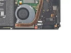
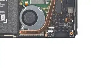
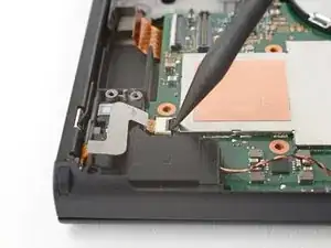
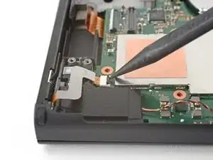
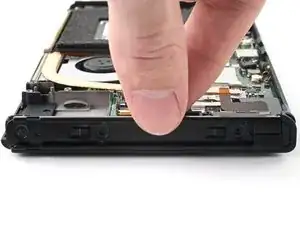
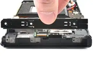
Use a Phillips driver to remove the 3.8 mm screw securing the right Joy-Con sensor rail to the rear case.
-
-
-
Use a Phillips driver to remove the 3.8 mm screw securing the left Joy-Con sensor rail to the rear case.
-
-
-
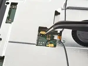
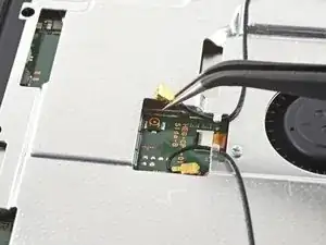
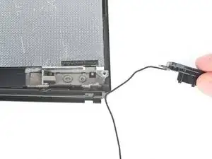
Use tweezers, or your fingers, to pull up and disconnect the primary Wi-Fi antenna's coaxial cable.
-
-
-
Use tweezers, or your fingers, to reroute the primary antenna's coaxial cable out of its slots in the shield plate.
-
-
-
Use a Phillips driver to remove the two 4.4 mm screws securing the primary Wi-Fi antenna to the shield plate.
-
-
-
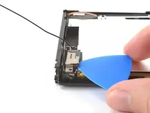
Insert an opening pick between the primary Wi-Fi antenna and the shield plate.
-
Pry up with the pick to separate the primary Wi-Fi antenna from the shield plate.
-
-
-
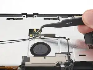
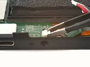
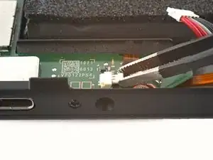
Use tweezers, or your fingers, to pull up and disconnect the secondary Wi-Fi antenna's coaxial cable.
-
-
-
Use the point of a spudger to reroute the secondary Wi-Fi antenna's coaxial cable from its slot in the frame.
-
-
-
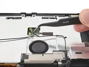
Use a Phillips driver to remove the 4.4 mm screw securing the secondary Wi-Fi antenna to the shield plate.
-
-
-
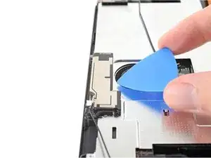
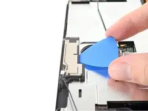
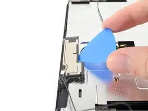
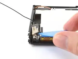
Insert an opening pick between the secondary Wi-Fi antenna and the shield plate.
-
Pry up with the pick to separate the secondary Wi-Fi antenna from the shield plate.
-
-
-
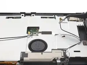
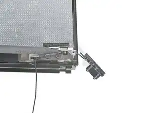
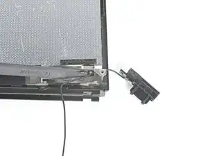
Use the point of a spudger to reroute the secondary Wi-Fi antenna's coaxial cable out of its slot in the frame.
-
Remove the secondary Wi-Fi antenna.
-
-
-
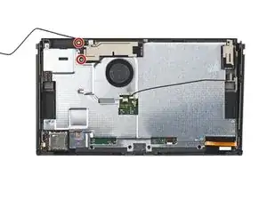
Use a Phillips driver to remove the six 4.4 mm screws securing the shield plate to the frame.
-
-
-
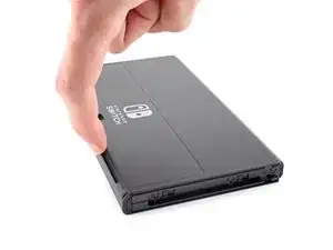
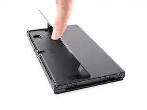
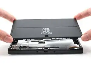
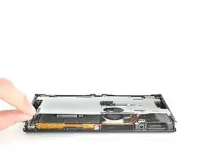
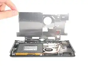
Use your fingers to lift the top of the shield plate up and away from the frame.
-
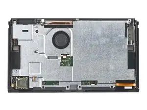
Remove the shield plate.
-
-
-
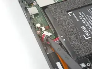
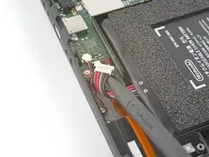
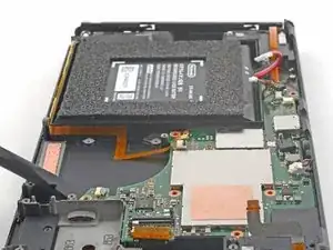
Use tweezers, or your fingers, to remove the piece of tape obscuring the daughterboard's screw.
-
-
-
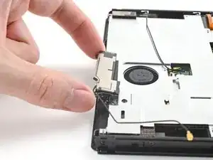
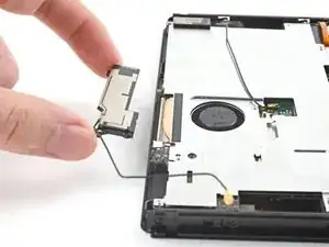
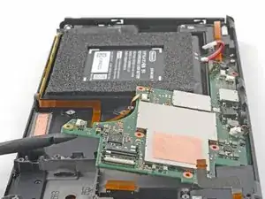
Insert a spudger between the edge of the daughterboard and the motherboard.
-
Pry up with the spudger to disconnect the press connector and separate the daughterboard from the frame.
-
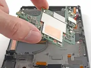
Remove the daughterboard.
-
-
-
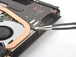
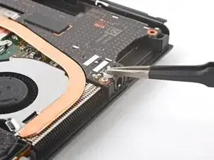
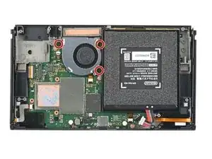
Use a Phillips driver to remove the three 3 mm screws securing the heat sink to the motherboard.
-
-
-
Insert a spudger between the heat sink's bracket and the motherboard.
-
Pry up with the spudger to separate the heat sink from the motherboard.
-
-
-
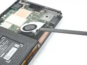
Insert a spudger in the gap between the fan and the heat sink.
-
Pry up with the spudger to separate the heat sink from the adhesive beneath it.
-
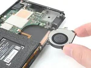
Remove the heat sink.
-
-
-
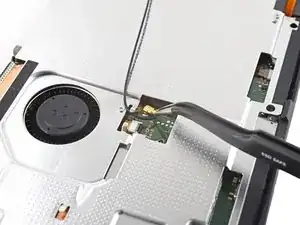
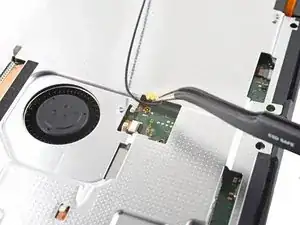
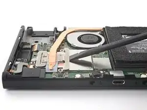
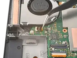
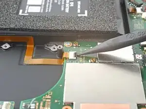
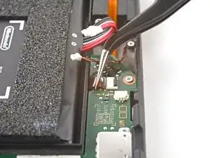
Use the tip of a spudger, an opening tool, or your fingernail to flip up the small, hinged locking flap on the fan cable's ZIF connector.
-
-
-
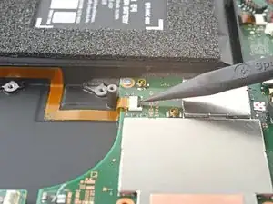
Use a pair of tweezers to pull the fan cable straight out of its connector on the motherboard.
-
-
-
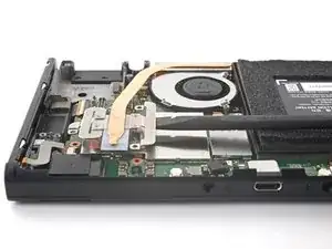
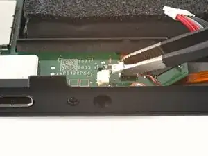
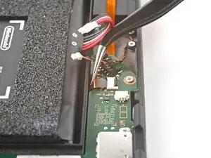
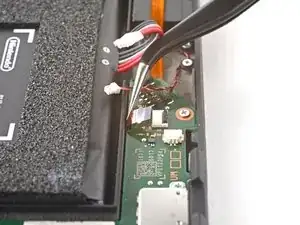
Use an opening tool, spudger, or your fingernail to flip up the small, hinged locking flap on the power button board's ZIF connector.
-
-
-
Use a pair of tweezers to pull the power button board cable straight out of its connector on the motherboard.
-
-
-
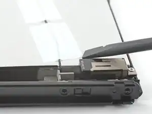
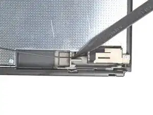
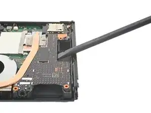
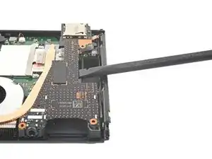
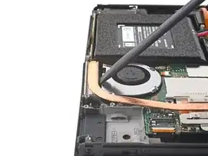
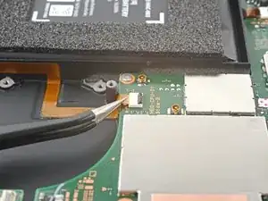
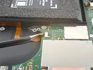
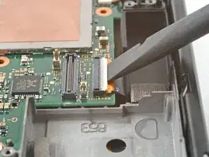
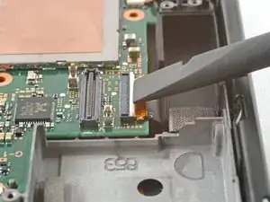
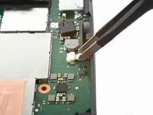
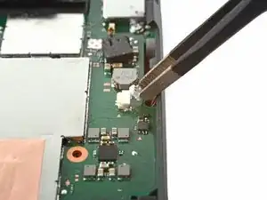
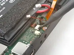
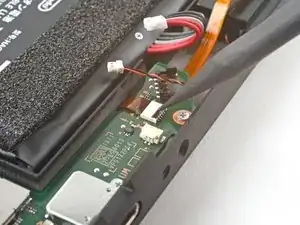
Use an opening tool, spudger, or your fingernail to flip up the small, hinged locking flap on the right Joy-Con sensor rail's ZIF connector.
-
-
-
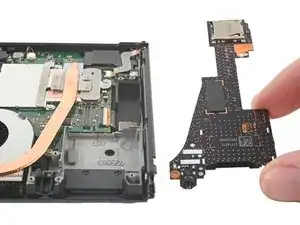
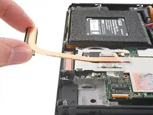
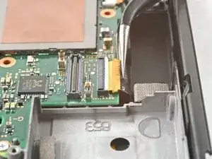
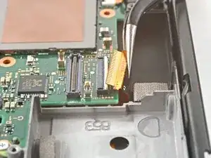
Use a pair of tweezers to pull the right Joy-Con sensor rail's cable straight out of its connector on the motherboard.
-
-
-
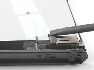
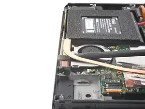
Use an opening tool, spudger, or your fingernail to flip up the hinged locking flap on the display's ZIF connector.
-
-
-
Use a pair of tweezers to pull the display cable straight out of its connector on the motherboard.
-
-
-
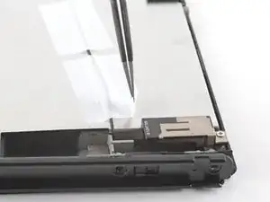
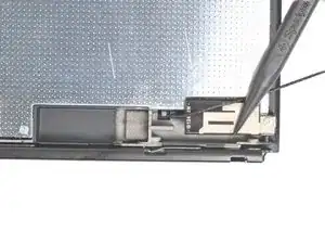
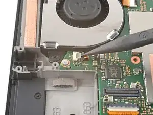
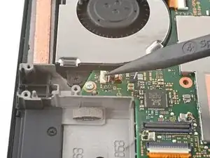
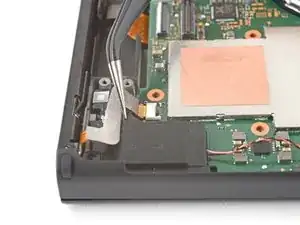
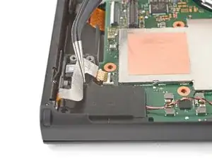
Use an opening tool, spudger, or your fingernail to flip up the small, hinged locking flap on the right Joy-Con sensor rail's ZIF connector.
-
-
-
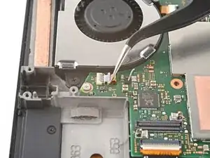
Use a pair of tweezers to pull the right Joy-Con sensor rail's cable straight out of its connector on the motherboard.
-
-
-
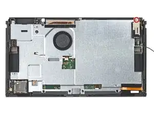
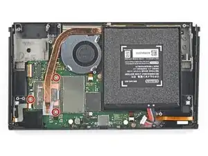
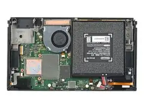
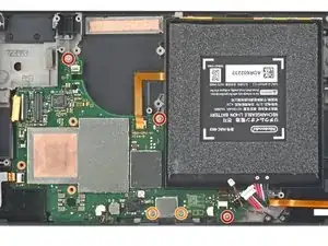
Use a Phillips driver to remove the five screws securing the midframe to the frame:
-
Three 3 mm screws
-
Two 4.4 mm screws
-
-
-
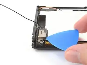
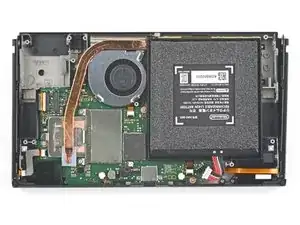
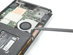
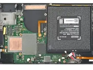
Insert a spudger between the motherboard and the frame.
-
Pry up with the spudger to separate the motherboard from the frame.
-
Remove the motherboard.
-


To reassemble your device, follow these instructions in reverse order.