Introduction
Outside of catastrophic impact damage, the main reason to replace a midframe on a Nintendo Switch is because the joy-con mounting rail has been brutally ripped from the midframe, leaving no solid mounting for a replacement rail available.
In order to restore the security of the joy-con mount, it is necessary to replace the entire midframe, and this guide will step you through the procedure.
Note: When you remove the shield plate, you’ll need to replace the thermal compound between the plate and the heatsink. Since normal thermal paste isn’t designed to bridge large gaps, the closest replacement is K5 Pro viscous thermal paste. You will, however, need regular replacement thermal paste for the CPU.
-
-
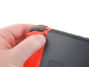
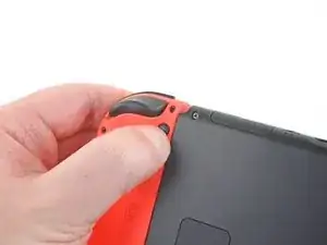
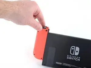
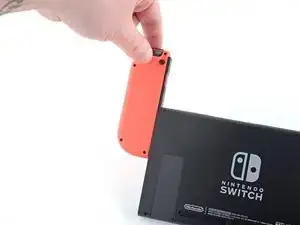
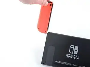
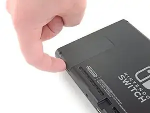
Press and hold down the small round button on the back of the Joy Con controller.
-
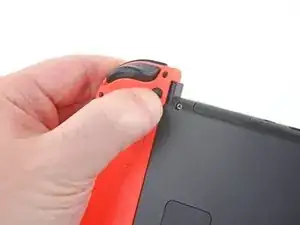
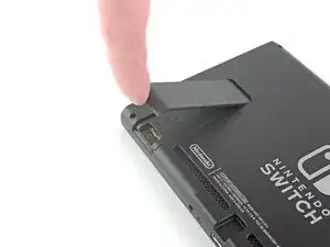
While you hold down the button, slide the controller upward.
-
-
-
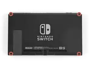
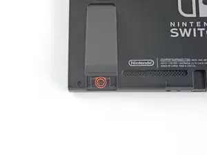
Use a JIS 000 driver or an official iFixit PH 000 driver to remove the following screws securing the rear panel:
-
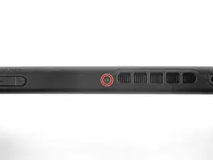
One 2.5 mm-long screw on the top edge of the device
-
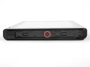
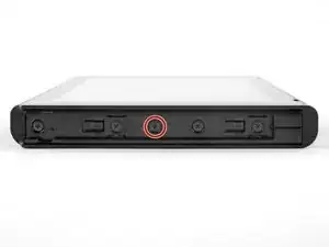
Two 2.5 mm-long screws on the bottom edge of the device
-
-
-
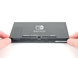
Use a JIS 000 screwdriver or an official iFixit PH 000 driver to remove the two 3.8 mm center screws on the sides of the device (one on each side).
-
-
-
Use a JIS 000 screwdriver or an official iFixit PH 000 driver to remove the 1.6 mm screw in the kickstand well.
-
Close the kickstand.
-
-
-
Open the game card cartridge flap.
-
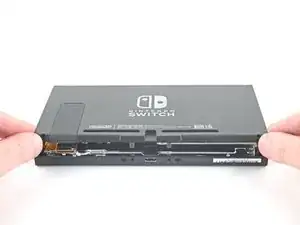
Lift the rear panel up from the bottom of the device and remove it.
-
-
-
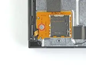
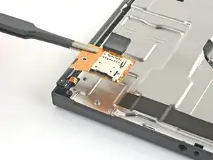
Use a JIS 000 screwdriver or an official iFixit PH 000 driver to remove the 3.1 mm screw securing the microSD card reader to the device.
-
-
-
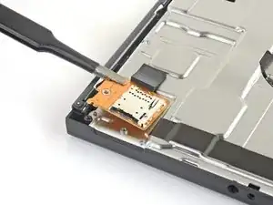
Use your fingers or a pair of tweezers to lift the microSD card reader straight up from the device to disconnect and remove it.
-
-
-
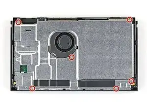
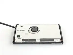
Use a JIS 000 screwdriver or an official iFixit PH 000 driver to remove the six 3 mm screws securing the shield plate to the device.
-
-
-
Use your fingers or a pair of tweezers to peel back the piece of foam on the top edge of the device near the fan exhaust port.
-
-
-
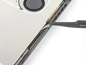
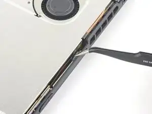
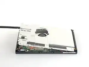
Insert a spudger underneath the shield plate along the edge of the device.
-
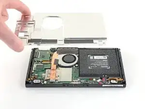
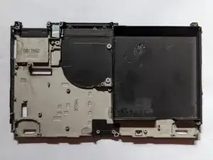
Pry up to lift the shield plate and remove it from the device.
-
You can reuse the pink thermal compound if you're careful. Keep the compound clean and make sure it makes solid contact between the heat sink and the shield during reassembly.
-
If you need to replace it, refer to our thermal paste guide to remove the old thermal compound and replace it with an appropriate compound, such as K5 Pro, during reassembly.
-
-
-
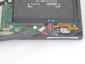
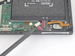
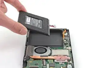
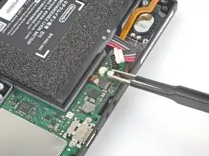
Use the point of a spudger to pry the battery connector straight up and out of its socket on the motherboard.
-
-
-
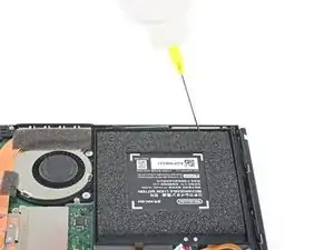
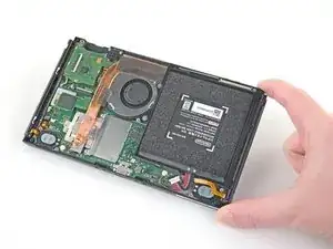
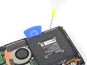
Apply a few drops of adhesive remover or high-concentration (90% or higher) isopropyl alcohol inside the battery well along the top edge to weaken the adhesive.
-
-
-
Tilt the top edge of the device upward to allow the isopropyl alcohol to work its way underneath the battery.
-
Hold for 1-2 minutes to allow time for the isopropyl alcohol to weaken the adhesive.
-
-
-
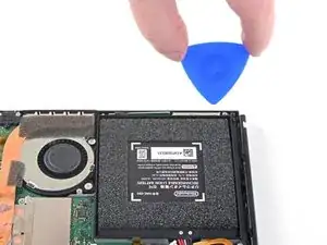
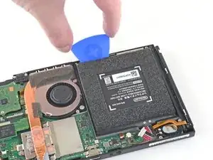
Insert an opening pick into the gap between the battery and the wall of the battery well.
-
Carefully dig the tip of the opening pick underneath the battery and slide it along the edge to begin slicing the adhesive.
-
-
-
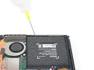
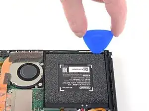
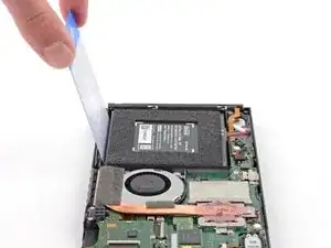
Leave the opening pick in place and apply a few more drops of adhesive remover or isopropyl alcohol inside the battery well.
-
Tilt the top edge of the device upward and wait 1-2 minutes for the isopropyl alcohol to weaken the adhesive.
-
-
-
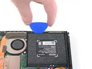
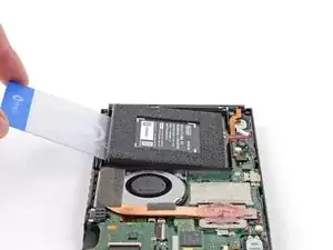
Continue sliding the opening pick deeper along the top edge of the battery, slicing more of the adhesive underneath.
-
-
-
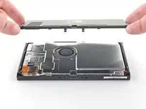
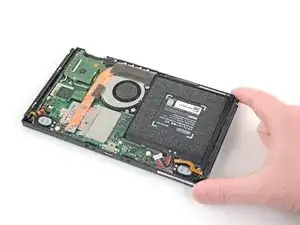
Once there's enough room, insert a plastic card underneath the battery and slowly pry the battery up.
-
Remove the battery.
-
-
-
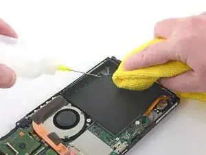
Use adhesive remover or isopropyl alcohol and a microfiber cloth to clean up any remaining adhesive left behind in the battery well before you install the new battery.
-
-
-
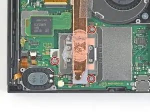
Use a JIS 000 screwdriver or an official iFixit PH 000 driver to remove the three 3 mm screws securing the heat sink to the motherboard.
-
-
-
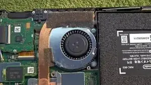
Carefully peel the two foam pieces stuck over both the heatsink and the fan away from the fan.
-
Insert the point of a spudger underneath the part of the foam that isn't stuck against anything,
-
Press the top of the foam with your finger to hold it in place.
-
Roll the spudger tip underneath the foam all the way to the other end of the foam to release it.
-
-
-
Use a spudger or your fingers to lift the heatsink up and off the motherboard to remove it.
-
Apply thermal paste to all surfaces that had thermal paste applied previously. This includes between the heatpipe and aluminum shield, which the Switch uses as additional heatsinking.
-
-
-
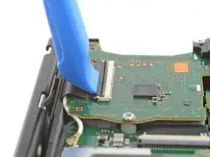
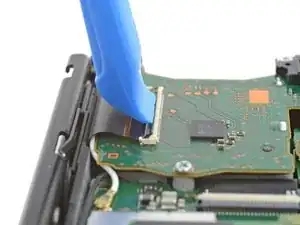
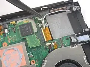
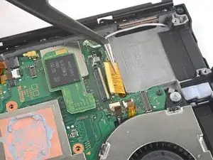
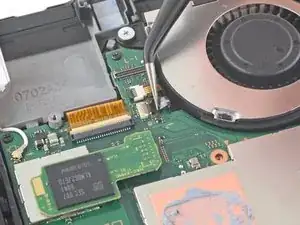
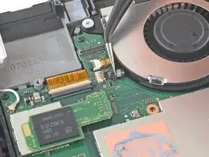
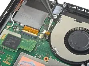
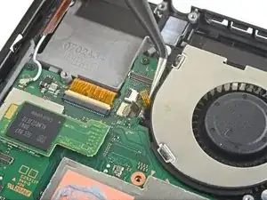
Use an opening tool or your fingernail to flip up the small, hinged locking flap on the digitizer cable's ZIF connector.
-
-
-
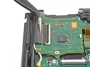
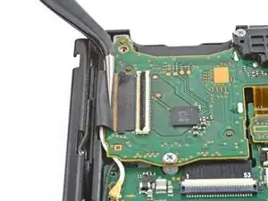
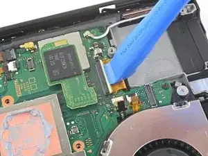
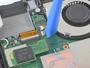
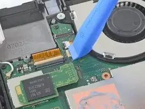
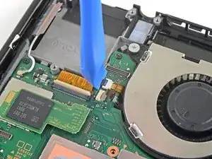
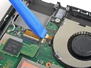
Use a pair of tweezers to slide the digitizer cable horizontally out of its connector on the game card reader board.
-
-
-
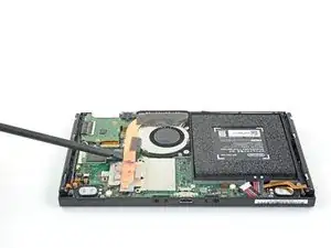
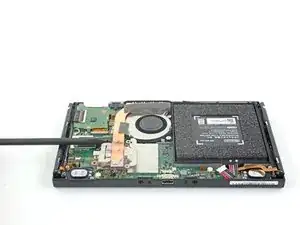
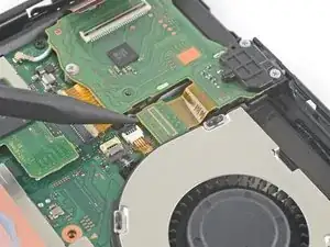
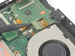
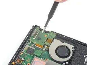
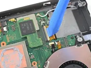
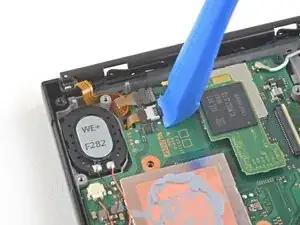
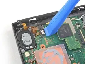
Use the point of a spudger to pry the headphone jack and game card reader connector straight up to disconnect it from the motherboard.
-
-
-
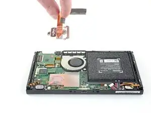
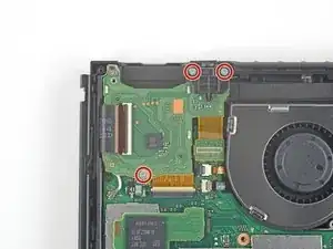
Use a JIS 000 screwdriver or an official iFixit PH 000 driver to remove the three 3.1 mm screws securing the headphone jack and game card reader board to the device.
-
-
-
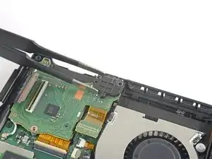
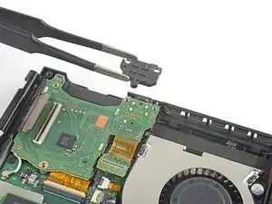
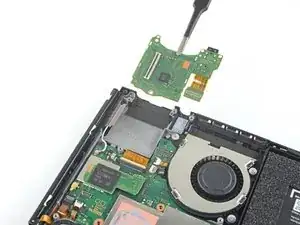
Use a pair of tweezers or your fingers to remove the headphone jack and game card reader board.
-
-
-
Use an opening tool, spudger, or your fingernail to flip up the small, hinged locking flap on the LCD ribbon cable ZIF connector.
-
-
-
Use a pair of tweezers to pull the ribbon cable straight out of its connector on the motherboard.
-
-
-
Use an opening tool, spudger, or your fingernail to flip up the small, hinged locking flap on the fan cable ZIF connector.
-
-
-
Use a pair of tweezers to pull the fan cable straight out of its connector on the motherboard.
-
-
-
Use an opening tool, spudger, or your fingernail to flip up the small, hinged locking flap on the power and volume button ribbon cable ZIF connector.
-
-
-
Use a pair of tweezers to pull the ribbon cable straight out of its connector on the motherboard.
-
-
-
Use an opening tool, spudger, or your fingernail to flip up the small, hinged locking flap on the smaller LCD ribbon cable ZIF connector.
-
-
-
Use a pair of tweezers to pull the ribbon cable straight out of its connector on the motherboard.
-
-
-
Use the point of a spudger, an opening tool, or your fingernail to flip up the small, hinged locking flap on the Joy Con sensor rail's data cable ZIF connector.
-
-
-
Use a pair of tweezers to pull the ribbon cable straight out of its connector on the motherboard.
-
-
-
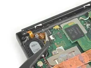
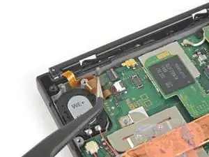
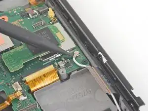
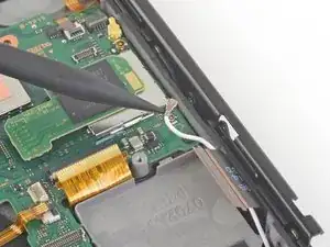
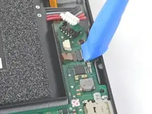
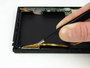
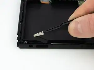
Use the point of a spudger to pry up the black antenna cable straight up out of its socket on the motherboard.
-
-
-
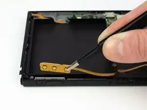
Use the point of a spudger to pry up the white antenna cable straight up out of its socket on the motherboard.
-
-
-
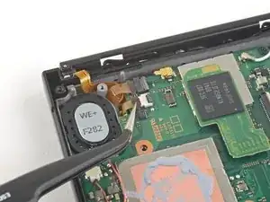
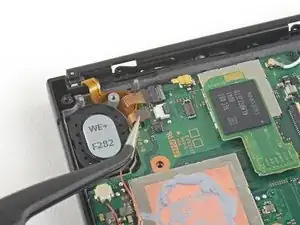
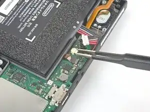
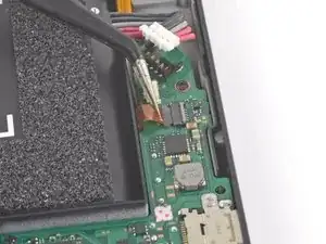
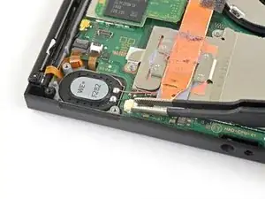
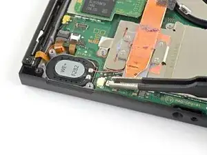
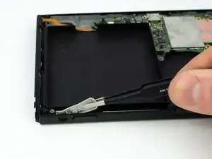
Use your fingers or a pair of tweezers to pull the right speaker connector straight out of its socket on the motherboard.
-
-
-
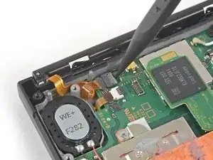
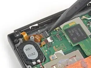
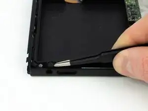
Use your fingers or a pair of tweezers to pull the left speaker connector straight out of its socket on the motherboard.
-
-
-
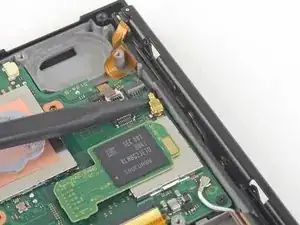
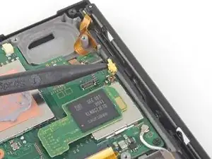
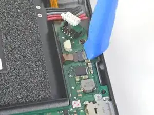
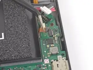
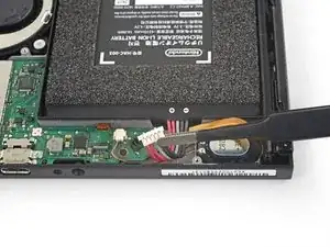
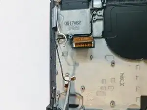
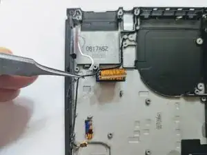
Use an opening tool, spudger, or your fingernail to flip up the small, hinged locking flap on the Joy Con sensor rail data cable ZIF connector.
-
-
-
Use a pair of tweezers to slide the Joy Con rail data cable straight out of its connector on the motherboard.
-
-
-
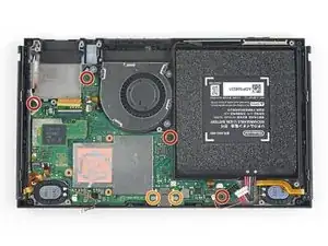
Use a JIS 000 screwdriver or an official iFixit PH 000 driver to remove the following screws:
-
Four 2.5 mm screws
-
Two 3.1 mm screws
-
-
-
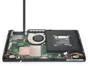
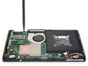
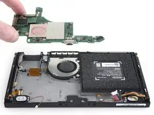
Insert a spudger into a gap between the motherboard and the frame.
-
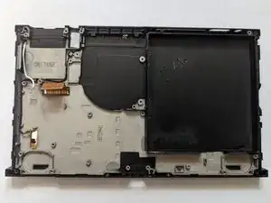
Carefully lift up the motherboard and remove it from the frame.
-
-
-
If you're replacing just the left speaker, skip the next two steps.
-
Use your fingers or a pair of tweezers to pull the speaker connector straight out of its socket on the motherboard.
-
-
-
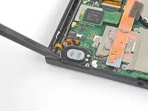
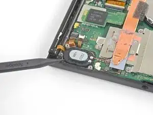
Use the point of a spudger to pry the speaker up.
-
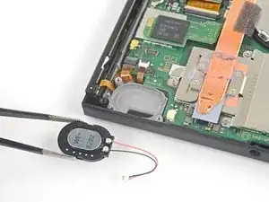
Use your fingers or a pair of tweezers to remove the right speaker.
-
-
-
Use your fingers or a pair of tweezers to pull the speaker connector straight out of its socket on the motherboard.
-
-
-
Use your fingers or a pair of tweezers to carefully remove the speaker from the speaker well.
-
-
-
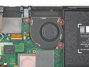
Use a JIS 000 screwdriver or an official iFixit PH 000 driver to remove the three 4.8 mm screws securing the fan.
-
-
-
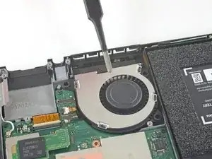
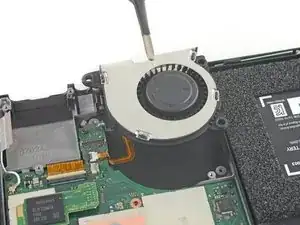
Use a pair of tweezers or your fingers to lift the fan straight up and remove it from the device.
-
-
-
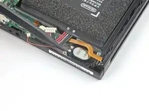
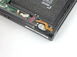
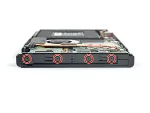
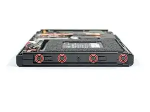
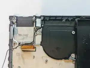
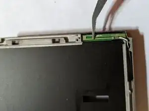
Use a JIS 000 screwdriver or an official iFixit PH 000 driver to remove the four 3.7 mm screws securing the right Joy Con rail to the frame of the device.
-
-
-
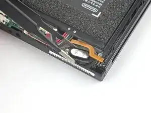
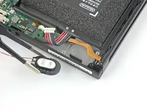
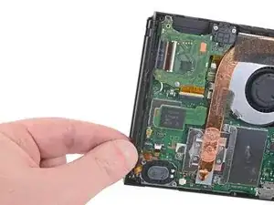
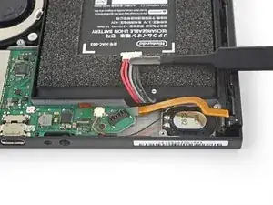
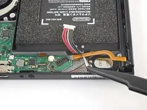
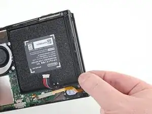
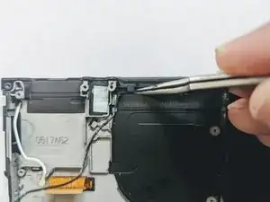
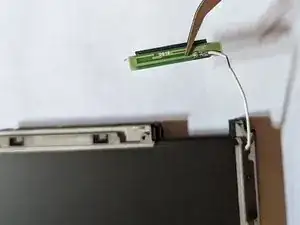
Use your fingers or a pair of tweezers to lift the battery connector up and out of the way of the Joy Con rail's data cable.
-
-
-
Use your fingers or a pair of tweezers to lift the battery connector up and out of the way of the Joy Con rail's data cable.
-
-
-
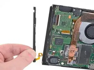
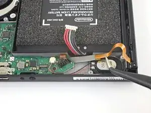
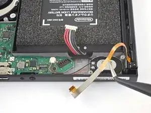
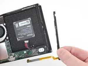
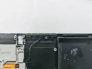
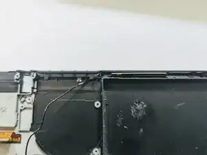
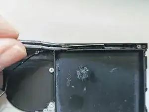
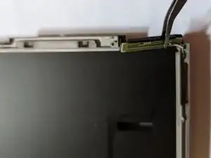
Use a JIS 000 screwdriver or an official iFixit PH 000 driver to remove the four 3.7 mm screws securing the left Joy Con rail to the frame of the device.
-
-
-
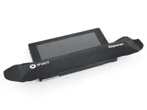
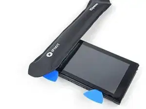
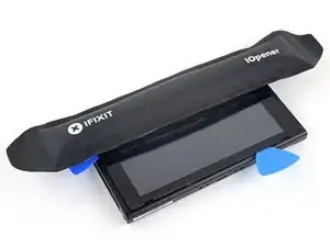
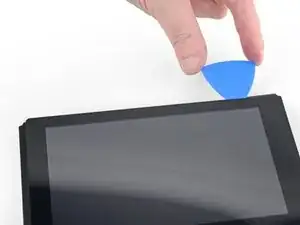
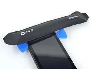
Heat an iOpener and apply it to the bottom edge of the screen for around two minutes to to help soften the adhesive.
-
-
-
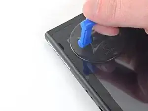
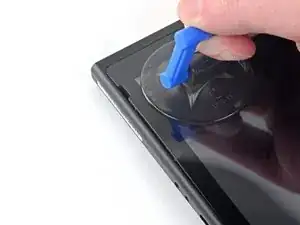
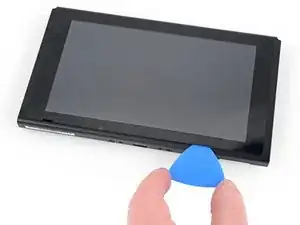
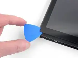
Apply a suction cup to the bottom-left corner of the screen.
-
Pull up on the suction up with strong, steady force to create a gap.
-
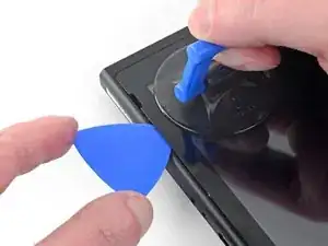
Insert the point of an opening pick into the gap, making sure to only insert the pick about 5 mm.
-
-
-
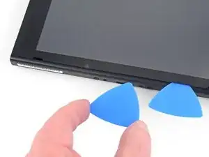
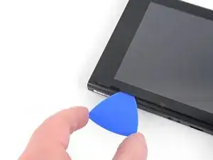
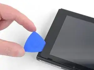
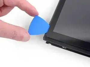
Slide the opening pick along the bottom edge of the screen to slice the adhesive.
-
Leave the pick inserted to prevent the adhesive from re-adhering to the frame.
-
-
-
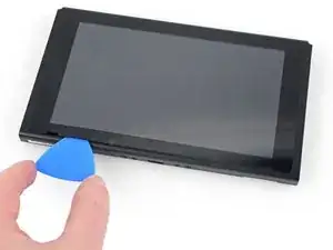
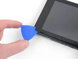
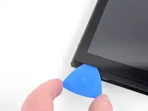
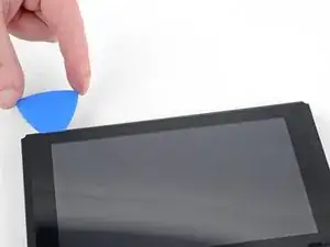
Insert a second opening pick into the gap to the left of the first pick.
-
Slide the opening pick back towards the left side of the device.
-
Leave the opening pick inserted.
-
-
-
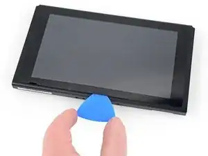
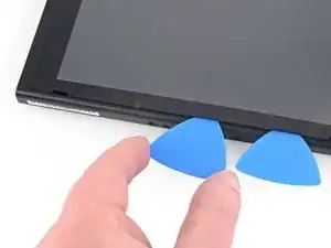
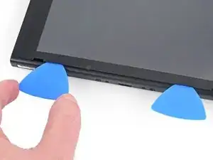
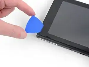
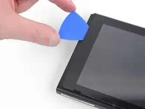
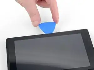
Continue sliding the opening pick around the top-left corner of the screen to slice the adhesive.
-
-
-
Heat the right edge of the screen for around two minutes to help soften the adhesive.
-
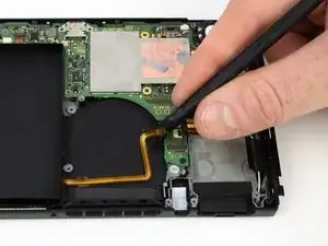
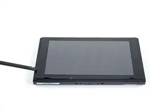
Place the flat end of a spudger into the gap along the left edge of the screen.
-
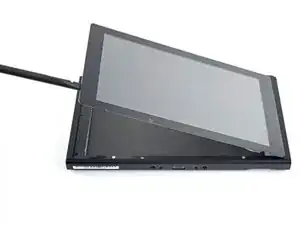
Carefully and slowly lift the left edge of the screen, opening it like a book.
-
-
-
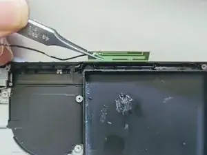
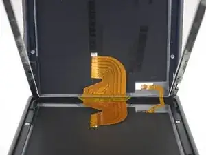
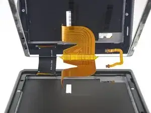
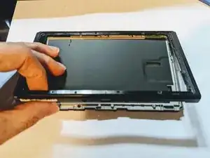
Lift the right edge of the screen straight off the device, threading the ribbon cables through the frame as you do so.
-
-
-
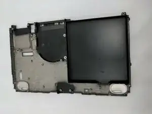
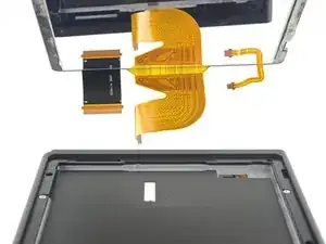
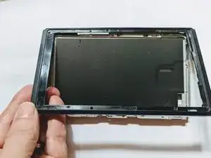
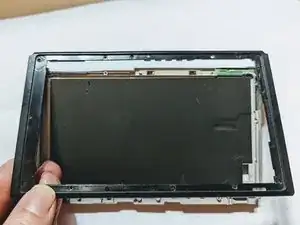
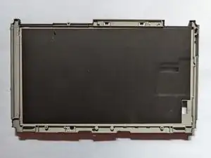
Lift the front edge of the frame then slide the frame up toward the top of the display to remove it.
-


To reassemble your device, follow these instructions in reverse order.

5 comments
Great guide will be attempting this soon so this guide has given me some hope! I can’t seem to find the black insulation layer on the last step would that be a generic insulating foam or something else?
Thanks, it should work, as I actually followed my own instructions the entire way through the replacement, although I had to add three other guides for completeness; the two antenna guides and the front frame guide.
I’m afraid I sidestepped the issue of the black insulation; I opted to buy a used frame that clearly showed the insulation still in place once I realized all of the new ones came without it. If you do come up with a solution for a replacement, we’d love to hear about it; I personally can’t think of a suitable substitute offhand.
Oh, one note on this guide; it’s put together using existing guides for the individual part removals, and as such it duplicates the instructions for removing some of the connectors such as the speakers and the display. So don’t worry if the instructions tell you to unplug a connector you’ve already unplugged; that’s just an artifact of combining separate guides. For example, both the motherboard and LCD replacement instructions tell you to unplug the LCD and digitizer cables
Thanks for the reply,
I was planning on doing this repair as a switch I have purchased has cracked plastic at the bottom of the casing where the fan vents are but I’m weighing up the pros and cons of stripping it down purely for that reason.
I can’t find a housing with that thermal pad anywhere which puts me off buying the ones that claim to be OEM if they don’t come with it by default.
I found some closed cell Polyethylene insulating foam sheets that are about 2mm thick so I’m assuming that’s similar on eBay so might give that a try and see how it compares to the original.
I poked around but had no luck finding anywhere the pad is sold separately; however I did come across a midframe being sold on Amazon with the pad (OEM pulls, removed from Switches). I’ve included a link in the parts list. The really good news is, it’s only about $11 US! Dang, wish I’d seen this when I was doing my replacement!
Hey Cameron, just re-reading your latest comment and I have to wonder if you really need to do a full midframe replacement. If its just cracked plastic, that should mean just doing a front frame replacement instead of a full midframe. Still a lot to do; the main differences are that you don't have to remove the battery and speakers which would be good as the battery is pretty hard to pull.
Kann ich diese Anleitung auch für die OLED anwenden? Habe im INet sonst leider nichts brauchbares gefunden.
Ina Barz -
backup all your sd card data i had to format mine after this tutorial and lost all my game data
JustForThisComment?ComeOn -