Introduction

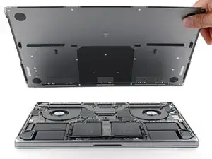
Use this guide to replace the heatsink in your MacBook Pro 16" 2023.

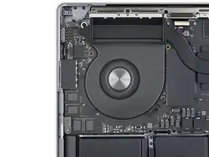
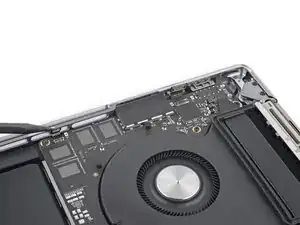
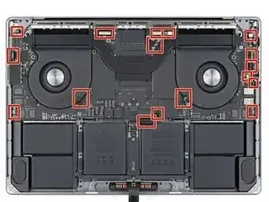
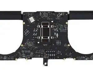
To access the heatsink, you'll need to remove the logic board.

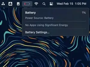
If your battery is swollen, take appropriate precautions.

Some photos in this guide are of the previous model MacBook Pro and may contain slight visual discrepancies, but they won't affect the procedure.

  1. CeHPQBrymZnLHPQ2
    CeHPQBrymZnLHPQ2
    GZnmgv3O2jnjxIKE
    mYQGVQelqZKMQxqn
    • Allow your MacBook's battery to drain below 10% before starting this repair. A charged battery may catch fire if damaged during the repair.

    • Fully shut down your MacBook, close the lid, and flip it over. Keep the lid closed until you've physically disconnected the battery.

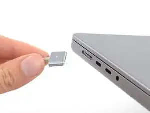
    • Unplug the MagSafe cable and any accessories connected to your MacBook.

  2. MElo1WJrYtdAY1cU
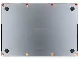
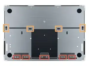
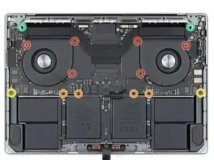
    • Use a P5 pentalobe driver to remove the eight screws securing the lower case:

    • Four 9.1 mm‑long screws

    • Four 6 mm‑long screws

    • Throughout this repair, keep track of each screw and make sure it goes back exactly where it came from.

  3. EMVn16dIXSnynasq
    EMVn16dIXSnynasq
    CvruIV6cgcERHVPu
    iWW3SZLcYO6DhLTF
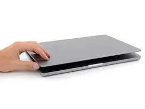
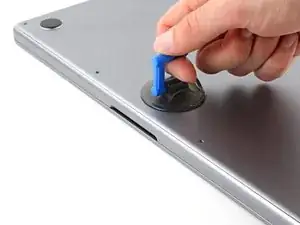
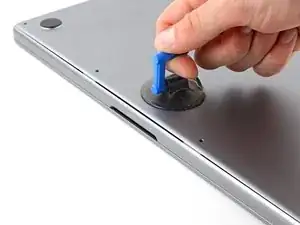
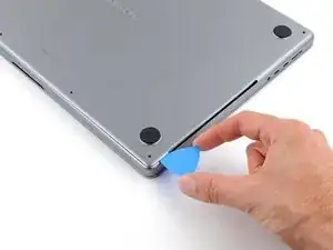
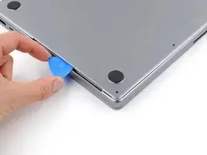
    • Apply a suction handle to the center of the lower case's front edge.

    • Pull up on the suction handle to create a gap between the lower case and the frame.

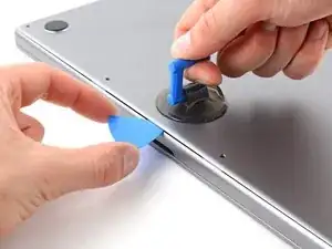
    • Insert an opening pick into the gap.

  4. VowKoKqQUTcJUW1Y
    VowKoKqQUTcJUW1Y
    BXFShFfEw3us3XYX
    tRxYm1oTMZ2VbiIM
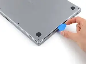
    • Slide your opening pick around the bottom right corner and up the right edge of the lower case.

    • If your pick gets stuck at the cutout, use your fingers to lift the lower case up slightly to allow your pick to slide underneath.

    • Slide your pick until it reaches the middle of the cutout, or until the rightmost clip stops it from sliding.

    • Twist your pick to release the two right clips.

    • You'll hear and feel a pop when each of the two clips releases.

  5. HpDiAZOlYlv3wWgh
    HpDiAZOlYlv3wWgh
    RZlpixTGXvHvkUcd
    5ofuLAdpsNnU5cJE
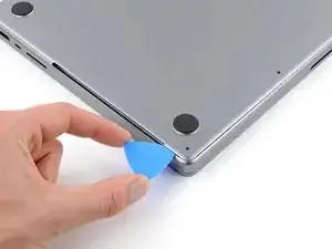
    • Slide your opening pick around the bottom left corner and up the left edge of the lower case.

    • If your pick gets stuck at the cutout, pry the lower case up slightly to allow your pick to slide underneath.

    • Slide your pick until it reaches the middle of the cutout, or until the leftmost clip stops it from sliding.

    • Twist your pick to release the left two clips.

    • You'll hear and feel a pop when each of the two clips releases.

  6. LHREHFMPXPennCxS
    LHREHFMPXPennCxS
    u6iVU2O1ASb5VFPY
    toTLPGIjhIL4THiP
    • Sliding clips along the back edge of the MacBook further secure the lower case. Separating these clips may require a lot of force—consider using gloves to protect your hands from the sharp edges of the lower case.

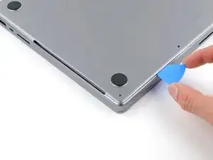
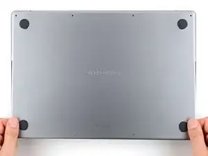
    • Firmly pull the lower case away from the back edge, one corner at a time, to disengage the sliding clips.

    • Keep the lower case flat to the MacBook. Don't pull upward until it's completely separated.

  7. XQYQqBTqQFYoVCoZ
    XQYQqBTqQFYoVCoZ
    QpCJcUDHqbNPZVk1
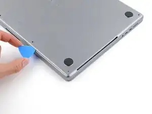
    • Remove the lower case.

    • To reinstall the lower case:

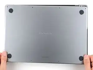
    • Lay it down and align the sliding clips with the back edge of the MacBook. Press down on the lower case and slide it toward the back edge to engage the clips.

    • When one side is engaged, it may push the other out of alignment. Check both sides as you push.

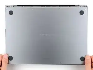
    • Once the back corners of the lower case are secured and flush with the frame, press down along the middle of the lower case to engage the four remaining clips.

    • You'll hear and feel each clip snap into place.

  8. JcOOIpGsWfqDMMmv
    JcOOIpGsWfqDMMmv
    YL6Y6wwsLwkXeZiJ
    1lHVOUPwGWrGncKG
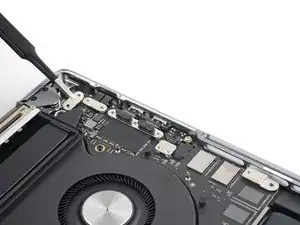
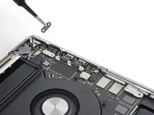
    • Use a T3 Torx driver to remove the two 2.1 mm screws securing the trackpad cable bracket.

    • Remove the bracket.

  9. Qc4GuMbcuMCL3SLS
    Qc4GuMbcuMCL3SLS
    QwiTu2ikpXKwaNKc
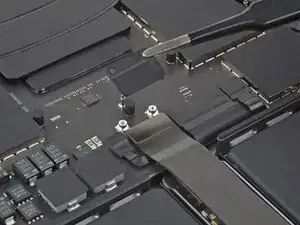
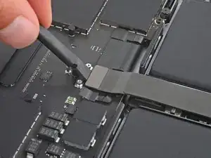
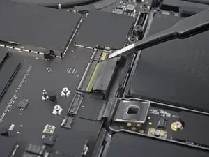
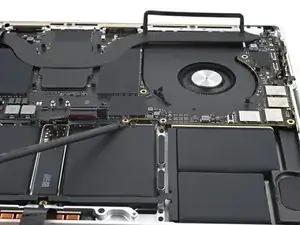
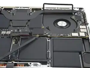
    • Use the flat end of your spudger to pry up and disconnect the trackpad cable press connector from the logic board.

    • To re-attach press connectors like this one, carefully align and press down on one side until it clicks into place, then repeat on the other side. Don't press down in the middle. If the connector is misaligned, the pins can bend and cause permanent damage.

  10. oeTgHAcLYWYcYeHS
    oeTgHAcLYWYcYeHS
    rBjK5quH3M3sfmXj
    pK1GcLMxaFsneyDx
    • The trackpad cable is lightly adhered to the battery board.

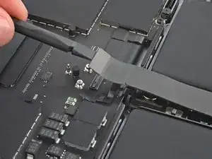
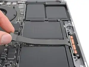
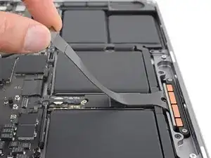
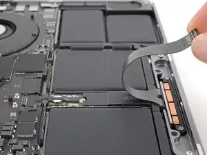
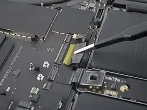
    • Peel the trackpad cable from the battery board.

    • Move the cable over the front edge of the MacBook.

    • Be careful not to crease the cable.

  11. pxWcWLWsSnhInhRx
    pxWcWLWsSnhInhRx
    xoYrIufNRWc1vqx2
    • Peel back the tape covering the battery data cable connector on the logic board.

  12. eGNLaxQdEbtAJmXL
    eGNLaxQdEbtAJmXL
    yYbnlPZWiDZhaAMH
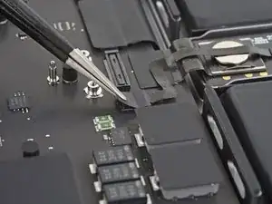
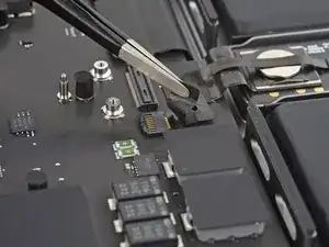
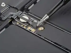
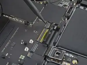
    • Use the point of a spudger or a clean fingernail to flip up the small locking flap on the battery data cable ZIF connector.

  13. meGcynWjFlcssBvR
    meGcynWjFlcssBvR
    CognANdCs4pyi4TJ
    IiMgwLToBvZsP1cx
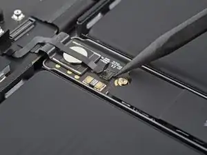
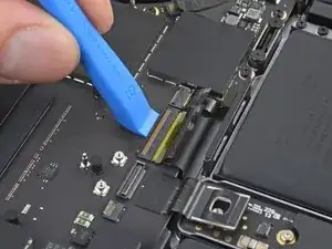
    • Slide one arm of your blunt nose tweezers under the battery data cable.

    • Grip the cable just below the head of the connector.

    • Slide the connector straight out of its socket.

  14. NGsyGhbUSbWICFZp
    NGsyGhbUSbWICFZp
    MYinewNtpNJ3r3Na
    • Peel back the tape covering the battery data cable connector on the battery board.

  15. BfQGmMdZbUNlUTkR
    BfQGmMdZbUNlUTkR
    RRoWSWQYJVoBFCTw
    YhwqdMUZL2ItpGPK
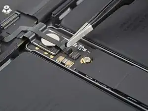
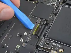
    • Use the point of your spudger or a clean fingernail to flip up the small locking flap on the battery data cable ZIF connector.

    • Use blunt nose tweezers to grab the battery data cable just under the head of the connector and slide it straight out of its socket.

  16. FmTwUfxVJu3cKwqI
    FmTwUfxVJu3cKwqI
    XPfLhUJuQ1POneUQ
    rbpHvx4LLyo5dl5h
    • The battery data cable is adhered to the battery board and logic board.

    • Peel the cable from the battery board and the logic board.

    • Remove the cable.

  17. SCPnnRC3SYHYfErs
    • Use a T5 Torx driver to remove the 3.9 mm pancake screw securing the battery connector.

  18. a2jJ4SCrLNXQmKAx
    a2jJ4SCrLNXQmKAx
    fBbCw3CeNrFC1qLm
    FnnxXRhXNC56QrGB
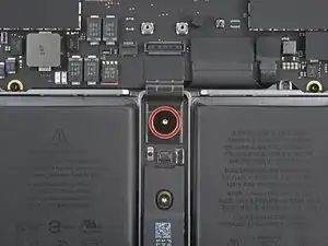
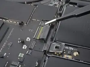
    • Use the flat end of your spudger to lift the battery connector away from the battery board, disconnecting the battery.

    • Lift the connector high enough that it doesn't accidentally make contact during the repair, but no more than 45 degrees to prevent damaging its hinge.

    • For added safety, place a barrier, such as a piece of a playing card, between the connector and board.

  19. TZhg5UGjQs5QTd1B
    TZhg5UGjQs5QTd1B
    kZbvhiyOWi66yncT
    D3Axo3yvafWVaLiv
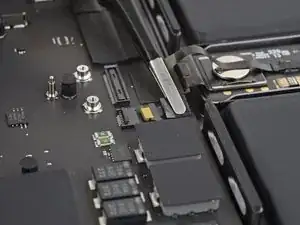
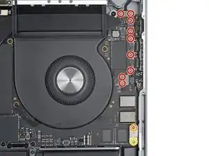
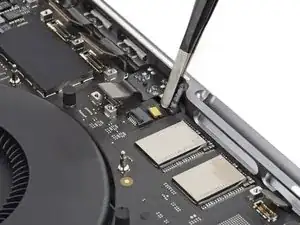
    • Use your T3 Torx driver to remove the three 2.1 mm screws securing the antenna cable cover and bracket.

    • Remove the antenna cable cover.

  20. HPPZZfWnnOoYeVDK
    HPPZZfWnnOoYeVDK
    kJZtEeJQWXi6EOjh
    ZctLUOsHIXqYAxxw
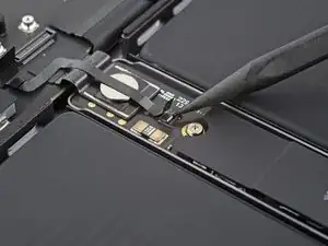
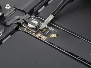
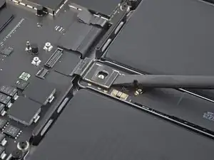
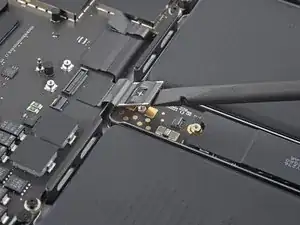
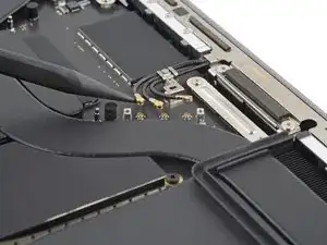
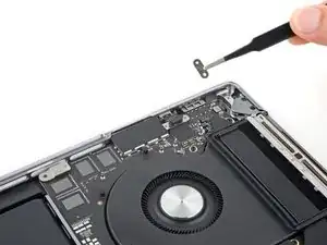
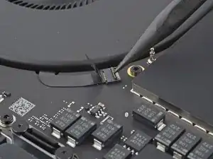
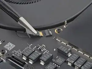
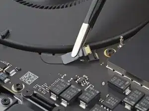
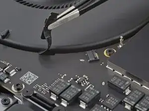
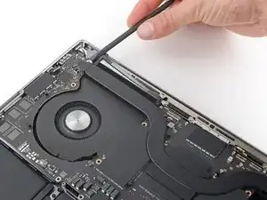
    • Use the point of your spudger to pry up and disconnect the three antenna cables from the logic board.

    • Pry only on the metal heads of the connectors. Avoid prying on the cables themselves.

    • To reconnect antenna cables like these, hold each one in place over its socket and press down with the flat end of your spudger. The connector will snap into place.

  21. LNvGWMjxwdkYesUp
    LNvGWMjxwdkYesUp
    1p1SBdkJXRrnI6ZM
    ePPFOjdI2wSLip4s
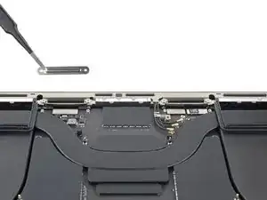
    • Use your T3 Torx driver to remove the four 2.1 mm screws securing the display cable covers.

    • Remove both display cable covers.

  22. cIbjXmav2kPNGOjZ
    cIbjXmav2kPNGOjZ
    elHCWnhD1D4IXNAA
    CorORDF15rXrOKmk
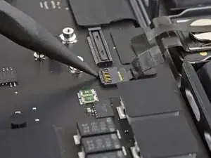
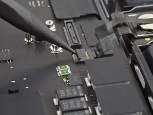
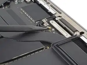
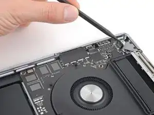
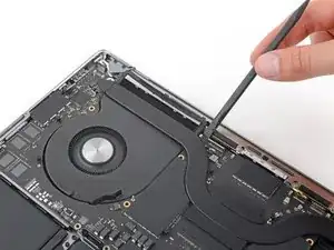
    • Use your spudger to pry up and disconnect all three display press connectors from the top of the logic board.

  23. mXoD3xwZHviUSY12
    mXoD3xwZHviUSY12
    dXpdcJ4HeHtRHn4s
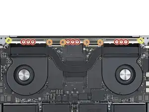
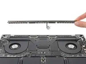
    • Use a P2 pentalobe driver to remove the nine 1.5 mm screws securing the antenna bar.

    • Due to their small size, these screws strip very easily. Make sure your driver is in good condition. Keep it vertical and apply constant downward pressure as you loosen the screws.

    • During reassembly, don't overtighten these screws—ensure that they're threading in properly, then tighten only until they're snug.

    • Use your T5 Torx driver to remove the six remaining screws securing the antenna bar:

    • Four 3 mm screws

    • Two 7.5 mm screws

  24. CXq2GDKClbwpkvfr
    CXq2GDKClbwpkvfr
    aKyGCa1LLIFsAHDZ
    • Pull the antenna bar straight up and out of the frame to remove it.

  25. RgRIoryKKbE4INxy
    RgRIoryKKbE4INxy
    Rm11OySKOLGGJYPE
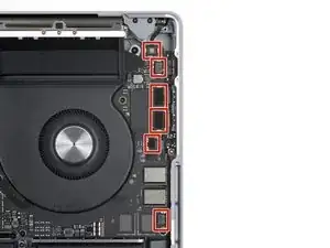
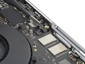
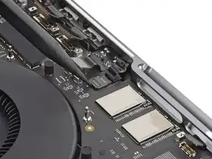
    • Use your T3 Torx driver to remove the 11 screws securing the five cable covers to the right side of the logic board:

    • Nine 2.1 mm screws

    • One 2 mm screw

    • One 3.5 mm screw

  26. myFDIGw4OwEGk5KR
    myFDIGw4OwEGk5KR
    B5Zlp66EtjkjZ46j
    Z2oOpoXlfYylrJID
    • Remove all five cable covers from the right side of the logic board.

  27. 6w2lklRkyXyHoj1q
    6w2lklRkyXyHoj1q
    KmKjP3mYjKLxiKPd
    WLaGrN35e2mdS5cT
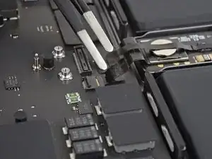
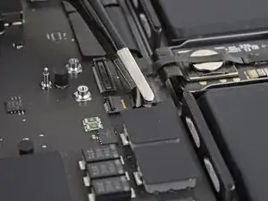
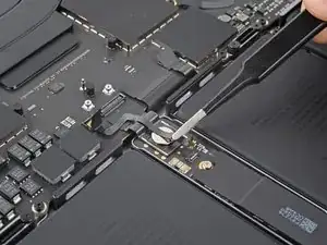
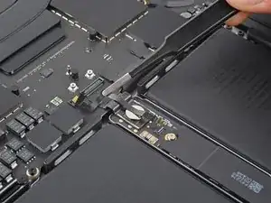
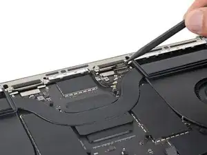
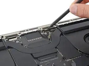
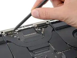
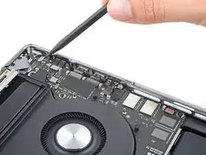
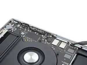
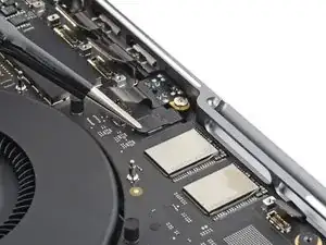
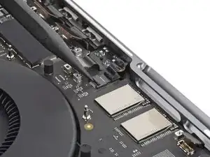
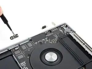
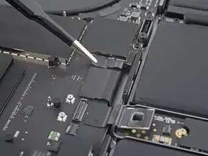
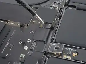
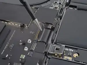
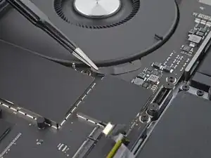
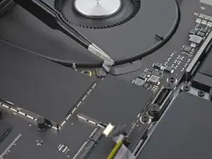
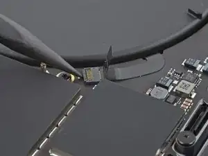
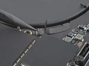
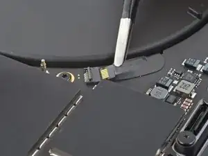
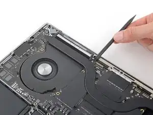
    • Use the point of your spudger to pry up and disconnect the six press connectors from the right side of the logic board.

  28. D2mqgxhPQ4kIO3aR
    D2mqgxhPQ4kIO3aR
    MMGtYAJGyoVSMlbd
    • Use blunt nose tweezers to peel back the tape covering the microphone connector.

  29. X1SGNoWRt2qdSu6v
    X1SGNoWRt2qdSu6v
    2yHpxvecTSOGEJBd
    QW6JpIFBHaOShYXi
    • Use the point of your spudger or a clean fingernail to flip up the small locking flap on the microphone ZIF connector.

    • Use blunt nose tweezers or your fingers to grip the cable tape and slide the connector straight out of its socket.

  30. 1WV6KYq3IkuZEPAT
    1WV6KYq3IkuZEPAT
    vPjMed1mZxOdVkIK
    • Use your T3 Torx driver to remove the six screws securing the three left cable covers to the logic board:

    • Four 2.1 mm screws

    • One 2 mm screw

    • One 3.5 mm screw

  31. WqZxQLOWEC2SPZny
    WqZxQLOWEC2SPZny
    lJIYCmqvRdyvuBMX
    BT5EcKxiF4nCykU5
  32. cHRG1FgtjfD1QEBE
    cHRG1FgtjfD1QEBE
    ovQYQgYPjZBCrR33
    K4qGMOtPj5Lmq11O
    • Use the point of your spudger to pry up and disconnect all three press connectors from the left side of the logic board.

  33. O6vZxWZSZRUAerfd
    O6vZxWZSZRUAerfd
    ysRkJO2t4eWeRins
    YbTrFR6lHdKctARW
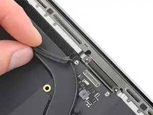
    • Use blunt nose tweezers to peel back the tape covering the keyboard and keyboard backlight connectors near the battery connector.

  34. VmBruYAnLqTNpY2Z
    VmBruYAnLqTNpY2Z
    6ydeZXTVAglVEOVp
    FGZc4XMY3FNYHxYN
    • Use the point of your spudger or a clean fingernail to flip up the small locking flap on the keyboard backlight connector.

    • This connector is the smaller of the two keyboard connectors.

    • Use an opening tool or two fingernails to flip up the locking flap on the keyboard connector.

    • This connector is the wider of the two keyboard connectors and may break if a narrow tool is used.

  35. KKsAimOePiRGZxwQ
    KKsAimOePiRGZxwQ
    blJx3MDEe5MWIAbW
    auPA2ceBXtPYJrgs
    • Grab the tape on the heads of the keyboard and keyboard backlight cables and pull their connectors straight out of their sockets.

  36. xjKWymSFtWUh3N5N
    xjKWymSFtWUh3N5N
    wfOts2YUSJtTKwuH
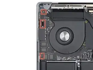
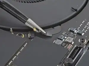
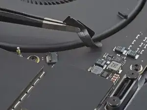
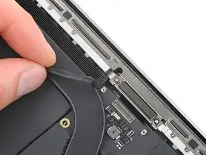
    • Use blunt nose tweezers or your fingers to peel back the tape covering the right fan connector.

  37. NgKhLTFtAVjG2ekN
    NgKhLTFtAVjG2ekN
    CJIBDfeXD5kZGgjd
    xJ5o2C4HICVPX5d2
    • Use the point of a spudger or a clean fingernail to flip up the small locking flap on the right fan ZIF connector.

    • Use blunt nose tweezers or your fingers to grip the cable tape and slide the connector straight out of its socket.

  38. YrXUydFS6Rdg12XV
    YrXUydFS6Rdg12XV
    OwLaeqPXsxCpbufs
    • The fan cables are very delicate. Be careful not to crease or tear them with your tools.

    • Peel up the right fan cable from the logic board.

  39. FNyhlKVJcmyArcBw
    FNyhlKVJcmyArcBw
    xlJt5rJCfgaEmRRt
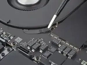
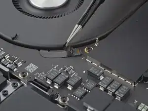
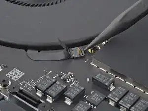
    • Use blunt nose tweezers or your fingers to peel back the tape covering the left fan connector.

  40. qqTpKiVeEjCpdHwW
    qqTpKiVeEjCpdHwW
    HWg4nZegsGjYgb31
    dLFgaJo4uWMKKrVF
    • Use the point of a spudger or a clean fingernail to flip up the small locking flap on the left fan ZIF connector.

    • Use blunt nose tweezers or your fingers to grip the cable tape and slide the connector straight out of its socket.

  41. bEiVLZXRjWcMCtAc
    bEiVLZXRjWcMCtAc
    EGFcQ4SgEOMAAtgl
    • Peel up the left fan cable from the logic board.

  42. aJGNQrCiHLvDLYwq
    aJGNQrCiHLvDLYwq
    qo2UnvkDkEX2et2X
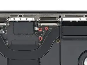
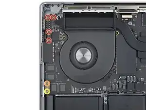
    • Use your T5 Torx driver to remove the ten screws securing the logic board to the frame:

    • Six 3.8 mm screws surrounding the fans

    • Four 4.6 mm screws along the bottom edge

    • Use a 4 mm hex driver to remove the two 6 mm-long standoff screws securing the bottom corners of the logic board to the frame.

    • During reassembly, first thread these bolts in with your fingers, then tighten them with your driver.

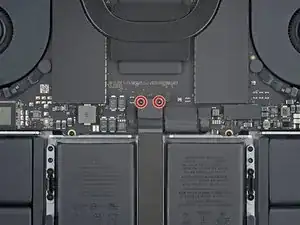
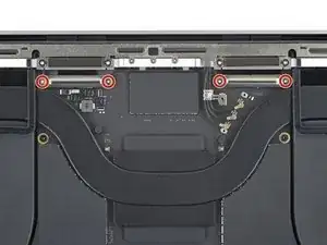
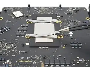
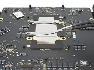
    • Use a T6 Torx driver to remove the two 6 mm screws securing the heatsink and logic board to the frame.

  43. WsOgNPrTrVFx2Rin
    WsOgNPrTrVFx2Rin
    2TGa1xcFeBAg3GCp
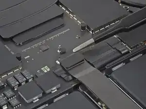
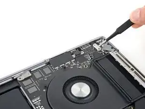
    • Insert the flat end of your spudger between the right side of the logic board and the frame.

    • Keep your spudger away from any cables or connectors on the logic board.

    • Gently pry the right edge of the logic board from its recess in the frame.

    • The logic board may catch on the press connectors. Hold the connectors out of the way as you lift the board, if necessary.

  44. UyNSBcMeMTP6rE3K
    UyNSBcMeMTP6rE3K
    RqVgSQqmlveOFuqy
    • Insert your spudger between the bottom edge of the logic board and the frame.

    • Gently pry up the logic board until you can grip it with your fingers.

    • Don't pry against the battery or any connectors. Use protrusions in the frame for leverage.

    • Hold the logic board up with one hand for the next two steps, as it tends to fall back into its recess.

  45. EZGFLi4IJVP6wOWF
    EZGFLi4IJVP6wOWF
    5pLgPSAqLTSXJfVu
    UBwXZwr6eniATOLk
    • The HDMI port, SDXC port, and the fins along the top of the heatsink hold the logic board tight to the frame.

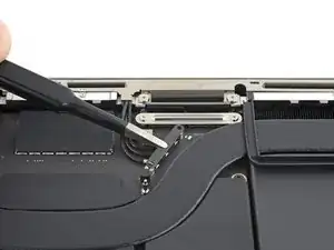
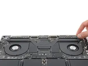
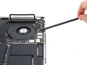
    • Insert your spudger between the middle of the top edge of the logic board and the frame.

    • Gently pry up until the fins along the top of the heatsink begin to lift from their recess in the frame.

    • The heatsink fins may catch on the left rubber gasket. Hold the gasket out of the way as you lift the heatsink, if necessary.

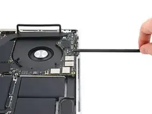
    • Insert your spudger at the top left edge of the logic board and pry it up over the left fan.

  46. t41SfiAl2axta3Cs
    t41SfiAl2axta3Cs
    O1hKBGFaQJmAQnyT
    ffHlDJSHBnWdEnSa
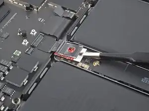
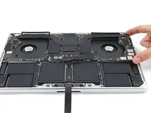
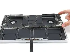
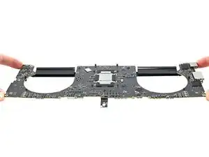
    • Lift the right edge of the logic board and pull it to the right to free the HDMI and SDXC ports from their recesses.

    • Guide the logic board out from underneath the display cables and the antenna cable bundle along the top edge.

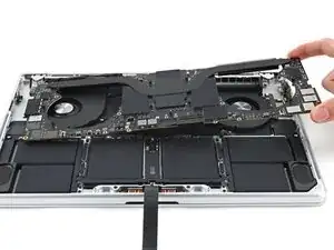
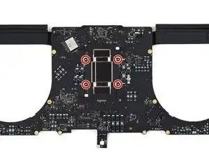
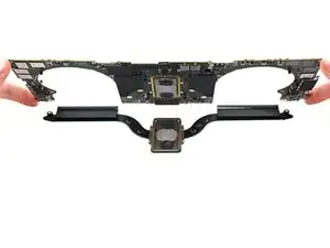
    • Remove the logic board.

    • During reassembly, insert the left edge of the logic board first to make sure the ports go into their recesses.

  47. T4K6weKYOTUhtUAP
    T4K6weKYOTUhtUAP
    gwMalt1s3y4aUIrj
    BUdLvHv2DqaYLxPx
    • During reassembly, note the following:

    • Make sure all 17 cables are above the logic board as you place it in the frame.

    • Use the point of your spudger to pull cables out from under the logic board if they slip underneath.

    • Hold the rubber spacers out of the way so the fins can drop into their recesses.

    • Align the heatsink by sliding the heatsink fins between the rubber spacers on each side of the MacBook.

  48. AYXrkKxgDPsXnjnl
    AYXrkKxgDPsXnjnl
    6IsQrOByRoOyZrFe
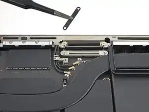
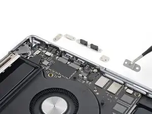
    • Flip your logic board over to access the screws on its underside.

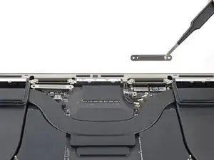
    • Use your T5 Torx driver to remove the four 3.9 mm screws securing the tension brackets to the logic board.

    • Gently hold the screws as you remove them, as the tension brackets may eject them.

    • During reassembly, loosely tighten these screws, then align the brackets and heatsink before fully tightening them in an X-pattern.

  49. jLSNy5lY3CPI2Gqd
    jLSNy5lY3CPI2Gqd
    A1LIPZG3uGICesuL
    • Remove the tension brackets.

  50. vgXeKYlc1yAYlpWr
    vgXeKYlc1yAYlpWr
    PyFXZHPiJxqaO4fN
    • Remove the logic board from the heatsink.

    • You may feel some resistance separating the logic board from the heatsink. This is normal, as thermal paste lightly bonds the two parts together.

    • During reassembly, clean and apply new thermal paste to the processor.

Conclusion

To reassemble your device, follow these instructions in reverse order.

Take your e-waste to an R2 or e-Stewards certified recycler.

Repair didn’t go as planned? Try some basic troubleshooting, or ask our Answers community for help.

Clay Eickemeyer

Member since: 19/09/22

65190 Reputation

0 comments