Introduction

Prerequisite only—use this guide to remove the logic board and heat sink together on the way to making repairs.

  1. dLTjRC36EADiCFBK
    dLTjRC36EADiCFBK
    FZYKkYtpGq1QwBO2
    YAOsWGKtCtOGVFRy
    • Before starting this procedure, you must disable your Mac's Auto Boot feature. Auto Boot powers on your Mac when you open the lid, and may be accidentally triggered during disassembly. Use this guide or follow the abbreviated instructions below to disable Auto Boot. This command may not work on all Macs.

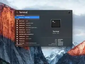
    • Power on your Mac and launch Terminal.

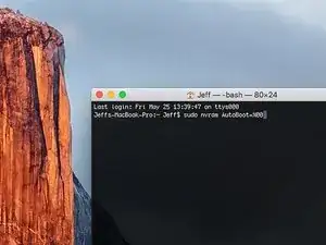
    • Copy and paste the following command (or type it exactly) into Terminal:

    • sudo nvram AutoBoot=%00

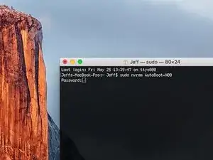
    • Press [return]. If prompted, enter your administrator password and press [return] again. Note: Your return key may also be labeled ⏎ or "enter."

    • You can now safely power down your Mac and open the bottom case, without it accidentally powering on.

    • When your repair is complete and your Mac is successfully reassembled, re-enable Auto Boot with the following command:

    • sudo nvram AutoBoot=%03

    Is this step necessary? I can’t perform this step as I am attempting to repair water damage and need to remove logic board & most likely replace the battery.

    Macrepair SF -

    @mac_medic You definitely don’t want the power coming on while the board is wet. In your case, I think powering on the machine to disable Auto Boot would do more damage than it prevents. I agree, skip this step and be prepared to disconnect the battery quickly if the laptop automatically powers on. Good luck!

    Jeff Suovanen -

    Thats right! You don't want power running while working on your logic board.

    Dan -

    This did not work when running High Sierra.

    Kyle B -

    Tried this on a 2018 MBP 13” Touchbar (there’s no iFixit guide for this model yet). Need to replace a broken screen.

    Luckily I managed to connect to an external screen (Cmd-Down Brightness to switch displays) and enter above command. Seems to work, but there’s another problem with this model - it powers up as soon as any key is pressed……. ffs <gnashes teeth>

    Cool_Breeze -

    I unscrew the battery first and wrap electrical tape over the logic board battery connector before attempting any repairs to the board. Haven’t had any problems yet and I’ve worked on about 10 of these models already. Also when you open the bottom case use a suction cup at the bottom and pull up then run a plastic spudger along the edges to disconnect the clips. Also only use a plastic spudger on the board. Saw a youtube video from a repair shop and he did not disconnect the power and used all metal tools during the entire process of removing the board. His last step was to disconnect the battery terminal.

    Brian -

    Is this step necessary if my mac can turn on? Battery fully dead(

    Nursat b -

    BEFORE YOU START: The included torx head stripped off before I was done (and you might need an additional T4) so stop now and go buy a good one. Also they fail to warn you above to get some blue threadlocker ahead of time.

    Jason Sherron -

    This command did not work for me and I read that sometime in later 2020 Apple stopped this command from working…any ideas on a work around?

    Patrick Machacek -

    Not able to do that with damaged screen

    richardjgreen -

    If you have a damaged screen you can still use a converter from thunderbolt (USB 3) to HDMI and plug your Macbook Pro to your TV as monitor display. Just make sure to chose the right Source (HDMI IN) in your TV. I did it and to make it work I unplug and plug again in my Macbook and so I could disable the Auto boot

    Roberto Sanchez Bustos -

    Hi. This does not work on 2018 13” MacBook Pro with Touch Bar. I did exactly this to disable auto boot. But when I check by using nvram -p it says: auto-boot true. Am I doing something incorrectly? I did everything step by step. Copied and pasted the sudo command, pressed enter and then entered my password. I have Big Sur 11.1 installed. Is there any other way since I need to replace the screen. Thank you. Adrian

    Adrian Vizik -

    Hi everyone. This is also a little pointless if you can’t see anything on the screen, and you don’t have a display adapter to USB C to display it. I agree with Brian about removing the back and disconnecting the battery cable before you even think about opening the lid of the MacBook. Applying the insulation tape is also a handy little tip that just makes sure there is no way to discharge from either the board or battery.

    Roberto Enrieu -

    running `nvram -p | grep 'AutoBoot'` in terminal verifies that it was accepted

    result: `AutoBoot %00`

    Marek Polák -

    Running Big Sur 11.6.7 on a 2019 16" MBP, it's "auto-boot". So it's: nvram -p | grep 'auto-boot' to display the current state, the default is true - and then to change it, sudo nvram auto-boot=false which turns it off.

    Ed Mechem -

    This step is completely unnecessary if you follow the guide to disconnect the battery properly. Just put some tape between the battery and logic board connection to prevent it from accidentally touching and therefore powering on the laptop.

    Grant Ormsby -

    It took me a few tries to make this command work, as I was able to copy and paste the command into Terminal, but could not type in my laptop’s password. I finally typed my password into a text document, copied it (command C), and then pasted it into Terminal and it worked.

    tommy404 -

    I didn’t do this. Mine never auto-booted before I replaced the battery. Now it does.

    hatuxka -

    BEFORE YOU DO ANYTHING - CHECK THE BATTERY!

    I-fixit sent me a bad battery, which I didn’t realize until it was already install. They sent me a new one, but I wasted hours uninstalling and reinstalled.

    Get a volt meter and measure the voltage on the output of the battery pack. If it reads 0 V, SEND IT BACK. It should read over 2 V.

    bcardanha -

    I've just received my replacement battery and it reads 0,042V between the two main connectors. Do you think it's dead?

    peter sussex -

    When I did this from Terminal.app within Recovery Mode, the “sudo” was not recognized but I could invoke it without the sudo part. It seems to have been accepted when looking at “nvram -p”

    johann beda -

    When in Recovery Mode, you already have superuser powers. So you don't need to prefix commands with the sudo command to invoke them with root privileges; you already have them. Do a pwd (print working directory) after opening Terminal in Recovery Mode, and you'll see that you're in the root user's directory.

    Ed Mechem -

    I received the battery kit for my 2018 MacBook Pro and as per the above comment from bcardanha - Oct 12, 2021, I checked the voltage on the pads marked + and - . It was zero volts so I panicked a bit.

    I sent a message on the iFixiT Facebook page and I got no reply. I finally found the customer service email for Ifixit Europe and sent them an email voicing my concern as I was not keen to work for couple of hours just to discover that the battery is faulty. I had an almost instant reply on the email (kudos to them) and they adviced me to go ahead and install the new battery as the voltage measured when battery is not connected is not relevant.

    I took a leap of faith and after two hours… the new battery showed 50% charge and everything seems to be working just fine. I am happy it worked.

    Mircea Comanici -

    After removing the old battery and installing the new battery I powered up the MBP before screwing the bottom on. I discovered the my keyboard would not function. It took a few hours of investigation and frustration that I discovered the track pad power ribbon had become partially dislodged from the trackpad. I was able to see that this through the little machined slot where the battery sat. I had to remove the trackpad to reinsert the power ribbon back into the connector in the trackpad. after reassembling and reinstalling the battery etc the keyboard worked. Just food for thought if your run into the keyboard issue.

    Ed Mease -

    This should be the default. IMO I tell you to power on - not the lid.

    G Sena -

    Est ce que cela fonctionne sur un macbook pro 2017 sans touchbar ?

    maël muzelet -

    Bonjour Maël, oui, ce tutoriel concerne "les MacBook Pro 2016 (et plus récents) et les MacBook Retina 12" 2017 (et plus récents)"

    Claire Miesch -

    Excellent instructions. I was able to follow and install the new screen. I recommend that you get a good set of tools before you begin. I started with an inexpensive repair kit bought online. The Penta and torx bits failed. I bought an IFIXIT kit with quality bits and I was able to do everything I needed.

    Tom Markham -

    If you're not running an admin account the sudo command won't work (which honestly, you should not be running admin). Rather than logging in to your admin amount via the OS, in the terminal type "login [admin username]," then the password and you'll be able to do the sudo command as described above. Once you're complete, type "logout [admin username]" and you'll be good to go. Obviously replace [admin username] with whatever the account name for your admin user is.

    arichard2401 -

    For those unable to complete this step because the screen is too damaged I recommend leaving your macbook on until the battery dies.

    Nicholas R Licato -

    Just replaced my 2018 15" MBP battery. Running Sonoma.
    I found no way to disable AutoBoot (The status can be checked in the Power section of system report).

    Anyway, i left my battery completely drain before opening the MBP, and had no issues during the process.

    Cédric Bontems -

    After sending this command in terminal when I checked what happens if I now open the lid, instead the screen lit slightly up (still black) then a battery symbol showing the charging state showed up.

    Now, after replacement of the battery, this is all I get to see.

    No reset of NVRAM nor PRAM helped.

    Currently the new battery charges (58% atm) and it feels like it‘s mocking me.

    webrockers -

    I suspected the keyboard or TouchID sensor wouldn’t work, so I went on and checked every connector.

    I missed connecting the left TouchID sensor from step 31.

    webrockers -

  2. 5iYIgSZgIU6hkP1B
    5iYIgSZgIU6hkP1B
    UVKOsGSvaL1OsSL3
    • Completely power off and unplug your MacBook Pro before you start. Close the display and flip the entire laptop upside-down.

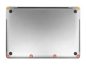
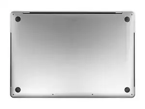
    • Use a P5 Pentalobe driver to remove six screws securing the lower case, of the following lengths:

    • Four 4.7 mm screws

    • Two 6.6 mm screws

    • Note how the screws come out at a slight angle—you must reinstall them the same way.

    • Throughout this repair, keep track of each screw and make sure it goes back exactly where it came from to avoid damaging your device.

    I miss a printable template to leave the screws and removed parts on it for future identification when reassembly, linked maybe with the location in the Macbook, or with the number of the step.

    Juan Ignacio Fernández García -

  3. ijkfCfPMSRX2ALo2
    ijkfCfPMSRX2ALo2
    5CkAq3GH4yfvDTM5
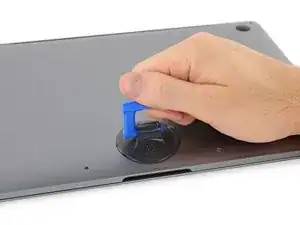
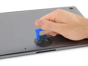
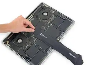
    • Press a suction handle into place near the front edge of the lower case, between the screw holes.

    • Pull up on the suction handle just enough to open a small gap under the lower case.

    Throw away this suction cup and get another. It just doesn't work! Luckily I had one that does work in my tool kit.

    Greek Taylor -

  4. 3tccyXXDSgVUfV5r
    3tccyXXDSgVUfV5r
    dGSZtjC2B25WfTqZ
    LkbLcUdZnPtyUlDZ
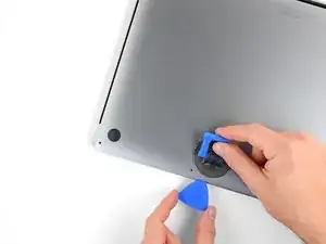
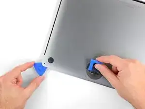
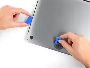
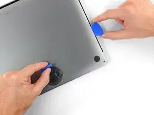
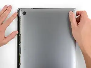
    • Slide the corner of an opening pick into the gap you just created underneath the lower case.

    • Slide the opening pick around the nearest corner and then halfway up the side of the MacBook Pro.

    • This releases the first of the hidden clips securing the lower case. You should feel and hear the clip pop free.

  5. HOVvMHuquXdBar2x
    HOVvMHuquXdBar2x
    oFJCHJDsnpdUHHUU
    ODWHnoCuXGXGKJla
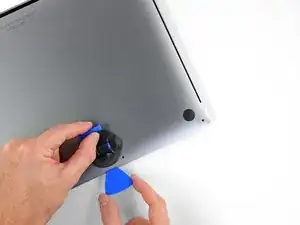
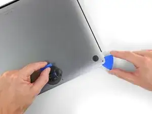
    • Repeat the previous step on the other side, using an opening pick to to release the second clip.

  6. cuTtNQlkiufuESrG
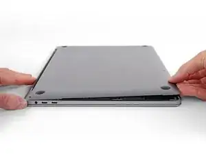
    • Lift the front edge of the lower case (the side opposite the display hinge) enough to slide your fingertips underneath and get a good grip on it.

    • Two additional hidden clips near the middle of the cover should pop free at this point, if they haven't already.

    • Don't lift more than an inch or so, and don't try to remove the lower case yet.

  7. rXaRTOtGXtFtIpF5
    rXaRTOtGXtFtIpF5
    AlvVmxKf6DlNLakh
    WJMFC2MdulDBxoXv
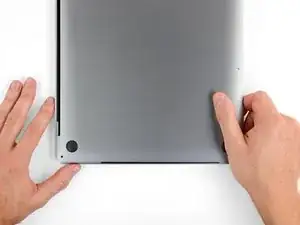
    • Pull firmly to slide the lower case towards the front edge of the MacBook (away from the hinge area) to separate the last of the clips securing the lower case.

    • Pull first at one corner, then the other.

    • Pull to the side—not up.

    • This may require a lot of force.

    With the amount of force needed to carefully pull the back panel out, this caused the back panel to scratch the battery. I don't see or hear any expansion, but this still has me concerned.

    gladgura -

    this step must require a lot of force. I tried to pull it with the plastic hookie thing from the ifixit set by hooking it in one of the screw holes — the tip of the hookie thing broke.

    Oleksii Toldaiev -

    The amount of force required for removing the bottom cover is absolutely ridiculous. Almost feels like i'm about to push my MacBook towards the wall the second it comes off.

    Be careful, I ended up breaking 2 grounding pins on the motherboard last time I tried opening my computer up.

    techtalkf -

    PLEASE DON'T PULL!!!

    Instead just gently push with plastic pick from the other side (where vents outputs are) towards the center... Cover will very easily open that way.

    I hope iFixit will correct this step.

    Kamil Roman -

    Came here to share exactly this.

    Robert -

    That's definitely how this step should be done. Thanks!

    VovS -

    If someone has a photo to share regarding this comment, it might be very useful. Thanks.

    Mark Cohen -

    I used a screwdriver at 45 degrees angle and pushed the cover from the hinges, it worked really smooth. I had it close to the corners.

    Martin Lundgren -

    Yeah, definitely don't pull; if you do, wear protective gloves. Mine was stuck so strongly that I just cut my palm quite deep.

    Kirill Chernov (PowerDoge) -

    You would think ifixit would investigate why the last step required them to pull with great force to remove the bottom case lid as the solution.

    It's counter-intuitive to use an excessive method to remove a part.

    There's always an easier way. It's frustrating because you can't see inside.

    Cary B -

    Using the iFixit opening Tool in the hinge opening required close to no force to open.

    Anders Markstrom -

    Ah... after attempting to 'pull' this rear cover off, to no avail, I tried to coax the cover off with a nylon pry tool. MUCH better! iFixIt will do well to amend it's recommendation to 'pull' this cover in any way. All I wanted to do was a little house cleaning and exorcize the dust bunnies that took up residence in my MBP's fans. Today is much quieter. Thank you all for pointing out the obvious.

    P.C. -

  8. 1eexZLVG2E3kwXhw
    1eexZLVG2E3kwXhw
    Koax55WG2pDjZ1MC
    WUXJn5rl13iOX11X
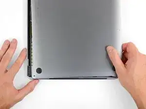
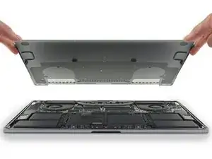
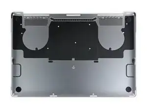
    • Remove the lower case.

    • To reinstall the lower case:

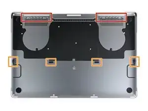
    • Set it in place and align the sliding clips near the display hinge. Press down and slide the cover toward the hinge. It should stop sliding as the clips engage.

    • When the sliding clips are fully engaged and the lower case looks correctly aligned, press down firmly on the lower case to engage the four hidden clips underneath. You should feel and hear them snap into place.

    If I had it all to do over, again, I would blow out the dust with compressed air at this point. During the disassembly, I kept encountering little dust bunnies, and I was very worried that one would get caught in one of the connectors when I plugged everything back up (which wouldn’t get discovered until I put it all back together and tried out all of the components).

    Joe Emenaker -

  9. PTIZqDdpESIEg6iK
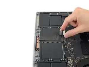
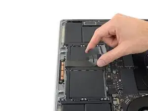
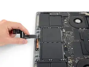
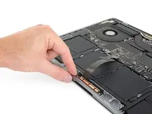
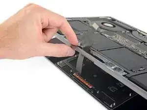
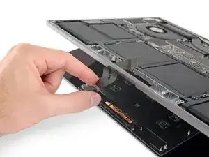
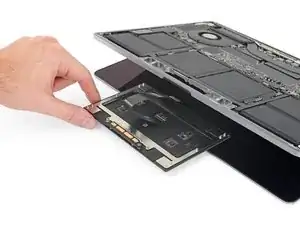
    • Peel up and remove the insulating sticker covering the battery board, on the edge of the logic board nearest the battery.

    • If the cover doesn't peel up easily, apply mild heat with an iOpener, hair dryer, or heat gun to soften the adhesive underneath, and try again.

    • If the cover doesn't seat securely during reassembly, try rotating it 180 degrees. It must be oriented correctly in order for the adhesive pads underneath to contact the board screws.

    i need a ziff connector flap for step 10

    Gregg Gorin -

  10. MZhqvhivJc6ltuBI
    MZhqvhivJc6ltuBI
    a5jICxWI6SwpreQK
    ur1oBPkypLAwkAay
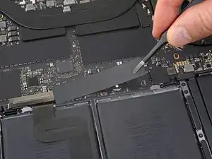
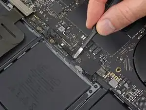
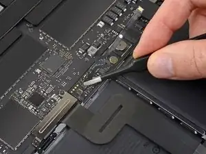
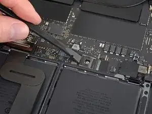
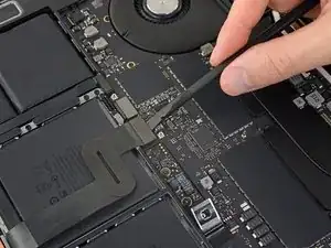
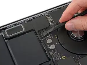
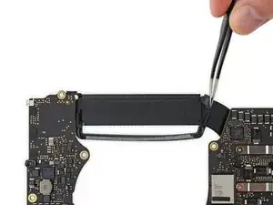
    • Peel back any tape covering the battery board data cable connector.

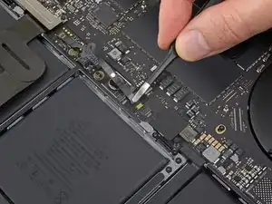
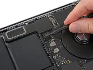
    • Use a spudger to gently pry up the locking flap on the ZIF connector for the battery board data cable.

  11. SBuNWrrEsnEHWE5U
    SBuNWrrEsnEHWE5U
    WSVYglC4kJSVXbLA
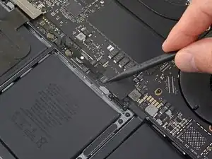
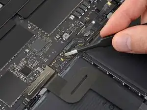
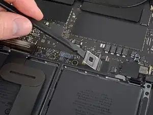
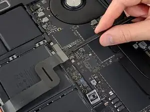
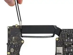
    • Disconnect the battery board data cable by sliding it out from its socket on the logic board.

    • Slide parallel to the logic board, in the direction of the cable.

  12. 3QMLTKDDDaOIEXZk
    3QMLTKDDDaOIEXZk
    QJeqYMjSJObGSxLc
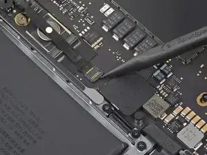
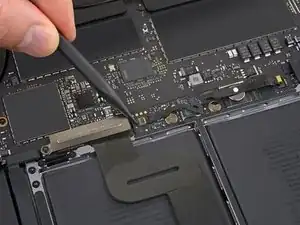
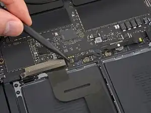
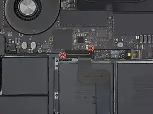
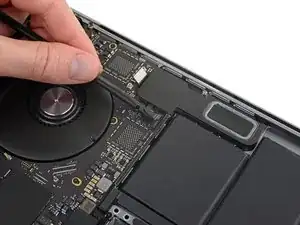
    • Pry up and disconnect the locking flap on the connector at the opposite end of the battery board data cable.

  13. doyrMkF4Ol2fsUCf
    doyrMkF4Ol2fsUCf
    FlF4ZwiPrAxEkwSi
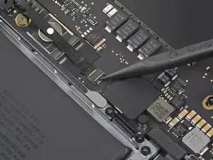
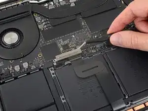
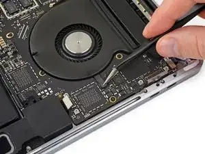
    • Slide the battery board data cable out of its socket on the battery board, and remove it completely.

    • Take care not to install this cable backwards or upside-down. When installed correctly, the white liquid indicator sticker should face up, positioned directly over the battery power connector screw.

    Bonjour, super Tuto, petite question elle sert a quoi cette nappe , et quesqui se passe si elle est pas branché ?

    Jorgio -aigleBrun- -

  14. YCrvX4dDTLFRo2He
    YCrvX4dDTLFRo2He
    REFmgM15LSgj5I14
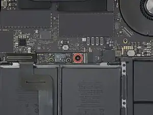
    • Use a T5 Torx driver to remove the 3.7 mm pancake screw securing the battery power connector.

  15. rmLuSU2NmsUdQIQp
    rmLuSU2NmsUdQIQp
    aMGREyB4myE324Ug
    • Use a spudger to lift the battery power connector, disconnecting the battery.

    • Lift the connector high enough to keep it separated from its socket while you work. If it accidentally makes contact, it could damage your MacBook Pro.

    Put a little bit of insulating tape over the terminal to be safe.

    Brian Tibbels -

    Agreed - once this is back in place, the system is energized, you run the risk of creating little sparks or worse if metal objects such as cover brackets accidentally touch areas of the logic board.

    bkbkbk -

  16. sK4lqBHxryavnDid
    sK4lqBHxryavnDid
    oF22XSHRWEFwHmoR
    • Use a T3 Torx driver to remove the two 1.9 mm screws securing the cover bracket for the keyboard and trackpad cable connectors.

    • Remove the bracket.

    I didn’t have T3 but T4 worked ;)

    Martin Lundgren -

    For my 2018 model year MBP, all the "T3" screws referenced here and later in the guide were actually T4 for me.

    Mint137 -

  17. ncIQWCHpRGO1fSb2
    ncIQWCHpRGO1fSb2
    yKukLfBQSF5SR1va
    • Use a spudger to disconnect the trackpad cable by prying its connector straight up from the logic board.

  18. noPvQ2CLs1jptX2p
    • Apply mild heat to the trackpad ribbon cable to soften the adhesive securing it to the battery.

    • You can use an iOpener, hair dryer, or heat gun, but be careful not to overheat the battery. The cable should be warm, but not too hot to touch.

  19. bRNYL1JeZ2MUeBe2
    bRNYL1JeZ2MUeBe2
    XJTjmkOpAHj1XPso
    irj3TcmYrfGAxaAU
    • Carefully peel the trackpad cable up off the battery, and push it out of the way.

    • Don't crease or tear the cable. If you have trouble, don't force it—apply more heat and try again.

  20. JDrgfAWr1UO6RLKu
    JDrgfAWr1UO6RLKu
    tCIssjKYVvECMJsB
    • Use a T5 Torx driver to remove the 13 screws securing the trackpad assembly:

    • Nine 5.8 mm screws

    • Four 4.9 mm screws

    • These screws all look similar—be careful not to mix them up.

    • Adding a little blue threadlocker to the screw threads during reassembly can help prevent the screws from working themselves loose over time.

    • Install the screws loosely at first, and then check the trackpad alignment before tightening them down.

    I dont have the “clicky” feedback from my trackpad anymore - please advise how to fix this

    Shadi Saif -

    The "clicky" feedback is achieved by electromagnet on the bottom, so for anyone like me who wanted to make sure it is working before connecting battery - it will not.

    Oleh Kasian -

    (MacBook Pro 2019 15” 2 years old) There are 4 screws (2 on the left and 2 on the right, each pair held down by a black metal piece) next to the uppermost 5.8mm screws. What is the size/kind of screw are these? I’d like to purchase these missing items? Please help. A suspicious technician tried to scam me out of money. I asked for my computer back before they could charge me. I decided to do the repairs myself. When I received my laptop back and followed Ifixit instructions I found 2 screws missing and they replaced the original with an unrecognizable rusty screw on the farthest left screw hole, and the black metal pieces were missing as well.

    Alathia Kaye -

  21. dbGJfyNAFLmgI6OQ
    dbGJfyNAFLmgI6OQ
    d31aHAXyDOBZbn6q
    WVy1FAO3B2SbT1ie
    • Swing the display open slightly, but keep the MacBook upside-down. The trackpad assembly should separate and lay flat on the display.

    • Carefully feed the trackpad's ribbon cable through its slot in the chassis.

    do not turn the touchpad over, as there are 4+5 very thin spacers/washers, and you might lose them. only the next step warns you about this. dont be me!

    George Kiss -

  22. yIm1JNUtPSAhyjoc
    yIm1JNUtPSAhyjoc
    AqeMok2AxKKOdhLZ
    NHbfjLZpScjEKpF5
    • As you remove the trackpad assembly, be very careful not to lose the nine small metal washers resting on the screw posts. (They will fly off and get lost with very little provocation.)

    • Remove the trackpad assembly.

    Und was wenn eine Trackpad Metallscheibe verloren geht?????Genau das ist mir gerade passiert. Muss ich mein Macbook jetzt wegschmeißen? HELP!

    Frank -

  23. ZWY2wWJIA2sohYJR
    ZWY2wWJIA2sohYJR
    VOv2slGFGMLOQBFe
    • Use your spudger to disconnect the keyboard by prying its connector straight up from the logic board.

    Yeah, nah. I'm going to be using Steve's method from Tronics fix to replace the battery in mine.

    I'm not messing around pulling the entire logic board out. 😁

    Cary B -

  24. 2ACOrmEBuVLGGMxV
    2ACOrmEBuVLGGMxV
    ESJgAWhAIByUZn5u
    • Use a T3 Torx driver to remove the two 3.5 mm screws securing the cover on the display board flex cable.

    • Remove the display board flex cover.

    I was able to complete this procedure successfully without removing the logic board. I don’t use any liquid adhesive remover. I employ A rubber type silicon rubber-semi stiff spatula used for putting icing on cakes. Use careful leveraged prying, sliding under battery to break the adhesive seal. Also careful application of heat with a heat gun being careful to not damage the speakers. I remove all logic board screws, disconnect all service cables including USB C caps on both sides. The goal is to be able to carefully ”lift” The lower edge of logic board most proximal to the battery enough to allow the ribbon cable to clear the “ridge” that is on rear edge of the battery compartment, Thus allowing you to pull the battery back horizontally towards The front edge laptop and out. I use popsicle sticks to keep the logic board lifted. Careful not to bend the board or break it! You need about 1/8” of clearance. 99% isopropyl alcohol libera dabbed on with a Q-tip to adhesive residue will clean it off.

    Macrepair SF -

    I had some issues using my T3 bit for most of these screws. Had to use a T4. Strange because I do not use either of those bits often, so I would assume they are still in good shape. Using a T3 felt like I was going to round out each of the screws. Wonder if anyone else experienced this same thing? I'm using the 'Pro Tech Toolkit' by iFixit.

    Michael Stein -

  25. h3LUEOUmG1Qa4FHB
    h3LUEOUmG1Qa4FHB
    jTMKbKYBPoyAAij6
    • Using a T3 Torx driver, remove the two 1.7 mm screws securing the bracket for the display board cable connector.

    • Remove the display board cable connector bracket.

    Help! I stripped the T3 Screw!! ?

    J S -

    I also did this

    jerryrobsonjr -

    Both of these screws also stripped for me. I’m not sure taking extra care would have helped: they stripped almost instantly and felt corroded. I basically continued by carefully manually turning out the right screw head using a regular, (slightly larger than T3) philips driver (and other small tools) until the head popped off the screw and one side of the bracket released. Then the bracket can be lifted and the other screw can be loosened using upward pressure. Upon replacement I basically used a small amount of high viscosity “gel” super glue (or epoxy) to reattach the right side of the bracket.

    capecodnative -

    Ok, I stripped it too. Feels like it isn't a t3 screw... Using the t3 bit from ifixit kit. Have a bite when turning clockwise but won't bite counter clockwise

    Chi Wang -

    Tried with another T3 bit (was using the T3 bit from ifix battery kit) and manage to remove one screw. The other one stripped too much but followed the recommendation from above comment about lifting the bracket

    Chi Wang -

    And now? It's definitely not T3. What the hell do I do now...

    Marina Llopis -

    Hey everyone, I stripped these screws also. Buy some VamPliers (5" Minis VT-001-5). These will get those screws out. I did the same thing and they worked! Amazon has them.

    Thom Hunter Pratt -

    Another one here with a stripped T3 screw at this section. Was the right screw for me. Got is out using a T4 bit.

    Kris Goodman -

  26. hWNUVuXxYGkOQLuW
    hWNUVuXxYGkOQLuW
    3lW4x2iOsthCyeb2
    • Pry the display board flex cable straight up from its socket to disconnect it from the display board.

    Having a lot of trouble getting this connector to re seat into its slot. It just won't snap back in. I've been trying for 30 mins. It doesn't appear to be damaged, but it just won't go back in and the display isn't working.

    Josh Rogers -

  27. NGFfbbntTcLfE6AN
    NGFfbbntTcLfE6AN
    TLBZSWgTQu1TCaxo
    • Use a T3 Torx driver to remove the four 2.0 mm screws from the hinge covers (two screws on each side).

  28. WESQjibowRGIOB4y
    WESQjibowRGIOB4y
    VQnIDOppIXlPfvOS
    dIZRRRhATdIGluks
    • Remove the two hinge covers.

  29. qxkZlsQjNTiqcykg
    qxkZlsQjNTiqcykg
    xxSD5pgXaB5CtOjl
    qEuLVDOGNShUMJU4
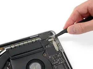
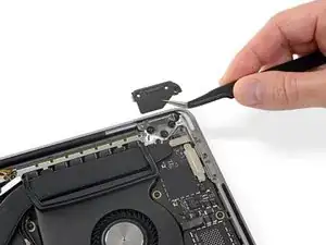
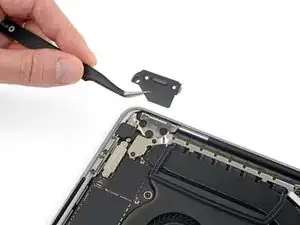
    • Use a T3 Torx driver to remove the two 2.4 mm screws securing the cover bracket for the Touch ID and headphone jack cable connectors.

    • Remove the bracket.

    Here is a first! I did not notice this when disassembling but spent a bit of time validating I had reassembled things correctly. After 35 years of this stuff, you don’t see much new - just smaller. !

    —->The 2.4 mm screw closest to the hinge screws into the logic board screw circled in green T8 (larger head)at step 47.

    Try finding that screw in your bucket of spares!

    Brian Eustis -

  30. K5fPx6JlRJOUXRMt
    K5fPx6JlRJOUXRMt
    k4hHBkxVZcreXFY6
    • Disconnect the headphone jack flex connector by prying it straight up from the logic board.

  31. LAcQL4JQvGZYGWGU
    LAcQL4JQvGZYGWGU
    GWgliFUh24bmRuLB
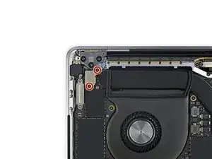
    • Disconnect the power button and Touch ID sensor by prying its connector straight up from the logic board.

    This smaller connector cable of the touch ID sensor that sits underneath the power sensor connector is easy to overlook when replacing the logic board. It is small & short and can easily hide. Make sure you account for it when placing the LB in and before screwing it down.

    Macrepair SF -

  32. JxwuAZXOHeF3CfYO
    • Using a T3 Torx driver, remove the 1.3 mm screw securing the cover bracket for the Touch Bar digitizer connector.

  33. gjGOmxTJPlV5Pcoi
    gjGOmxTJPlV5Pcoi
    ajmGXYArtoeYfTZx
    BQ33qY5wqiop1X2p
    • Using your tweezers, slide the bracket toward the side edge of the MacBook Pro until it clears the slotted retaining tab on the logic board.

    • Remove the bracket.

  34. OLEyZERLrZmuCWOc
    OLEyZERLrZmuCWOc
    YtBrywD3Z46KJOeH
    • Disconnect the Touch Bar digitizer cable by prying it straight up from the logic board.

  35. Z4WLmC4Af1MgSPwC
    Z4WLmC4Af1MgSPwC
    TBEkxgCdmTZxTq3D
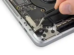
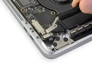
    • Use a T3 Torx driver to remove the two 1.9 mm screws securing the bracket for the Touch Bar display cable connector.

    • Remove the bracket.

  36. rdtc2HfFhemuFkP5
    rdtc2HfFhemuFkP5
    V1lJDfNAwoMJh5VT
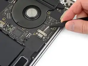
    • Disconnect the Touch Bar display cable by prying its connector straight up from the logic board.

    Right above the connector, there might be a chip attached instead of an empty space as shown in the photos. The connector will be close to the part but they are separate, and the connector can be safely removed.

    yqy980210 -

  37. Zg64coNjUyXMTLDc
    Zg64coNjUyXMTLDc
    sfFumwaPW4PM65rF
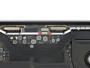
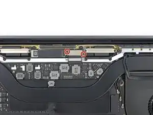
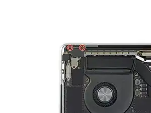
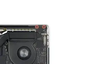
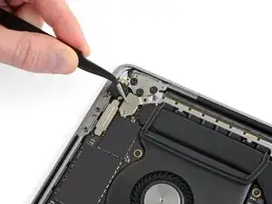
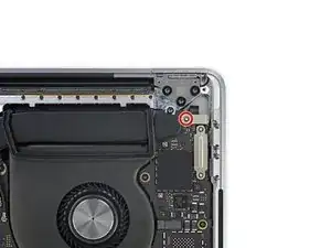
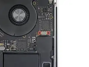
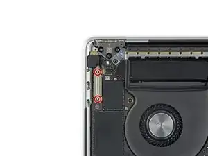
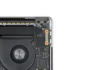
    • Using a T3 Torx Driver:

    • Remove the two 1.3 mm screws securing the Thunderbolt flex cable cover on the left.

    • Remove two more 1.3 mm screws from the Thunderbolt cable cover on the right.

  38. 3knbjJPAymkOLNCS
    3knbjJPAymkOLNCS
    y3lqPE4HW5nqZoLc
    • Remove the cover brackets from both Thunderbolt cable sockets.

  39. exkgTpYLnlrp4ZZQ
    exkgTpYLnlrp4ZZQ
    AjPJJxTGA5lLBtP5
    EMn4AYmTfpTaIJEl
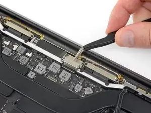
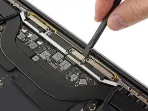
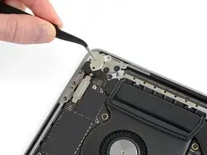
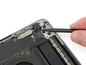
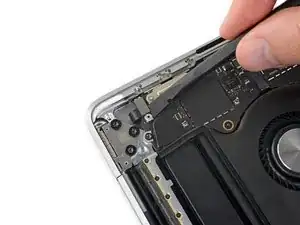
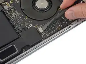
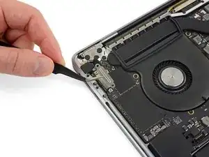
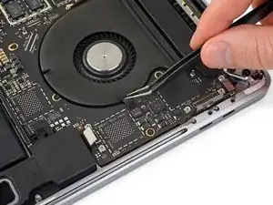
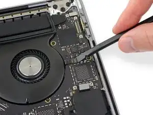
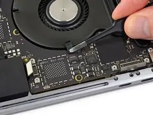
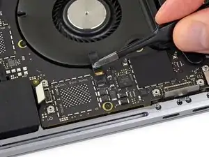
    • Use a spudger to disconnect the left-side Thunderbolt flex cable by prying it straight up from the logic board.

    • Pry from the inside edge, nearest the fan.

    • Gently push the flex cable connector off to the side so it doesn't interfere with logic board removal.

  40. LLsCNB1DthkUlIUN
    LLsCNB1DthkUlIUN
    pQTUTCUHTKgBFrqY
    JcyNSZmtHhshuhtq
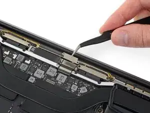
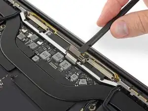
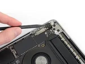
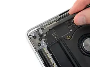
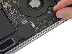
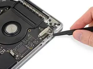
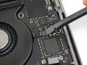
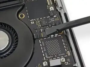
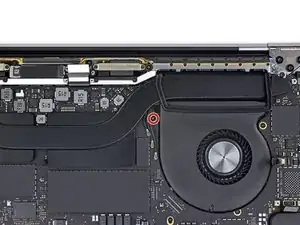
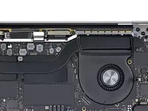
    • Repeat to disconnect the Thunderbolt flex cable connector on the opposite side.

    • Carefully push the flex cable connector aside so there's clearance for the logic board to come out without snagging.

  41. JGtZy3HuTUAeBoS3
    JGtZy3HuTUAeBoS3
    dRMCKLupNlCc3a52
    RODaAEUfwKQAvROr
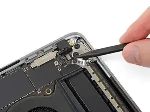
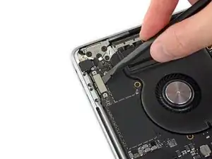
    • Disconnect the two speaker connectors by sliding the flat end of your spudger underneath each cable near its connector.

    • Gently twist or pry up to disconnect both speakers.

    Both had a dab of glue underneath. I used heat gun to loosen.

    Macrepair SF -

    On this step, it helped to use the tip of sharp tweezers to open the small metal tab of the connector to the side.

    Rodrigo Damazio Bovendorp -

    After disconnecting the speaker connector, does the speaker just come out, or is it glued or screwed in place? All I need is to Replace the Right Speaker with a New one. This guide gets me to this point but doesn’t address replacing the speaker. Would like to know if it’s more complicated than that before I get started… Thanks

    Would be nice to have a guide just for Speaker Replacement. Thanks

    Chad Gagnon -

    My right speaker doesn't work now because the cable and connector disconnected from the logic board. From one problem to another now... What should I do?

    Blake Johnson -

    ⚠️ DON'T DO THIS FOR THE LEFT SPEAKER!

    The right speaker has a six-pin connector which is wider than the spadler. The procedure described is correct.

    But the left speaker has a four-pin connector, narrower than the flat end of your spadler. If you slide it under the mat and lift, even gently, you will pull the connector off the motherboard.

    And, like me, you'll get the same problem as Blake Johnson.

    PS : Why six and four pins for a speaker?

    Francis Gernet -

  42. rpggR1BSd2ivkpCK
    rpggR1BSd2ivkpCK
    Uvg1Erp6vCnduApZ
    • Peel up any tape covering the microphone cable connector socket.

    Wenn möglich das Klebeband nicht abziehen! Zwei Schritte weiter bist Du froh darum.

    Stephan Zenger -

  43. jjBThQOLxxBKWtSw
    jjBThQOLxxBKWtSw
    e2dCqFryAVygfQOT
    cZSamwZeQZBWJkFL
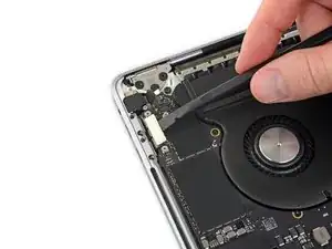
    • Open the locking flap on the microphone cable's ZIF connector by prying it straight up from the logic board.

    During reassembly, when trying to lock the ZIF connector flap, the flap jumped out of the connector.

    If this happens to you and you are lucky, as I was, maybe it is not broken. It is possible to fix it, but you will need dexterity and patience as this is a very tiny part.

    I had to go and get my watchmaker eyeglass to actually see what was going on.

    I also found this iFixit tutorial. Here is the link so you don't have to look for it:
    Replacing a ZIF Connector Locking Flap

    Cédric Bontems -

  44. TBowkAlrNvEIkWWt
    TBowkAlrNvEIkWWt
    kbuC4BITFsryhKqX
    • Disconnect the microphone by pulling its cable toward the fan until it releases from its socket.

    • If possible, pull on the tape attached to the cable, rather than the cable itself, to reduce the risk of damage.

    At this stage, when reassembling, I did disconnect the zif connector locking flap.

    If this happens to you, it is not necessarily broken. It can be fixed with very fine tweezers, a good magnifier, and a bit of patience.

    I had to go and get my watchemaker magnifier to achieve this.

    Here is a link to the tutorial if you need it:

    Replacing a ZIF Connector Locking Flap

    Cédric Bontems -

  45. 3P3EHShbtOjwWNJh
    3P3EHShbtOjwWNJh
    VHL2DsARcfi1pSAC
    • Use a T5 Torx driver to remove the single 2.9 mm screw securing the antenna cable bundle.

  46. IxDlbVhlHngl4Cxd
    IxDlbVhlHngl4Cxd
    CKA1yXuOSnccWLUF
    mjRiQRjFyFmNqOS2
    • Disconnect all three antenna cables by prying each one straight up from its socket.

    • Slide your tweezers or the flat end of your spudger underneath each cable until it's near the socket, and then gently twist or pry up to disconnect it.

    • To reconnect each cable, align the connector directly over its socket, and then press down so it snaps into place.

  47. mdXPZEvBWOLGqRA2
    mdXPZEvBWOLGqRA2
    eMnIAYVCqpZXJAha
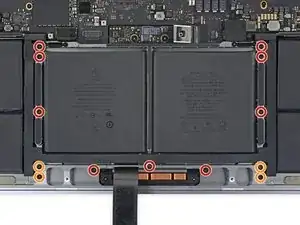
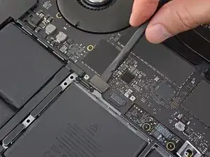
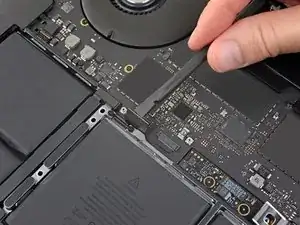
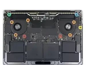
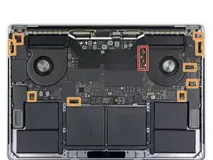
    • Remove all ten screws securing the logic board assembly:

    • Two 2.6 mm T3 Torx screws

    • Five 2.9 mm T5 Torx screws

    • One 3.7 mm T5 Torx screw

    • One 3.9 mm T8 Torx screw (large head)

    • One 4.0 mm T8 Torx screw

    • During reassembly, install these screws only loosely. Adjust the board position if necessary until all the connectors line up, and then tighten the screws.

  48. rCxHE2kgOHPDxy1D
    rCxHE2kgOHPDxy1D
    fkOuMFLayRPhvTCB
    CRooRPymdyPD4OUW
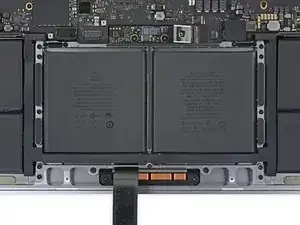
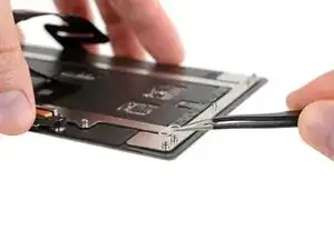
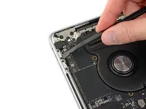
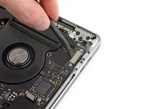
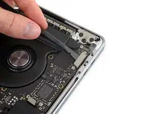
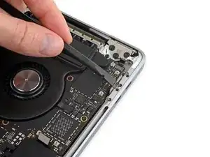
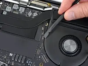
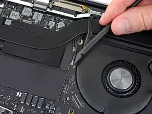
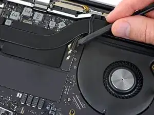
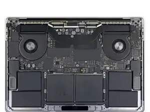
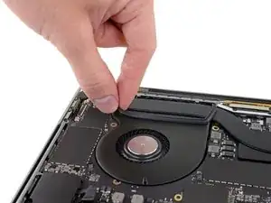
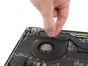
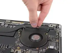
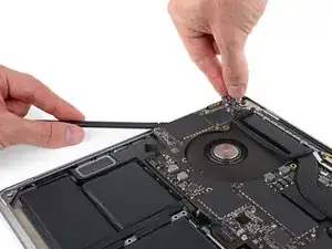
    • Peel up (but don't remove) the two rubber vibration damping strips from the adhesive holding them to the fans.

    • If needed, apply mild heat with an iOpener, hair dryer, or heat gun to soften the adhesive and make the dampers easier to separate.

    When replacing the battery, you can leave these, and just lift the logic board, enough so the battery slides out.

    nbeijer -

  49. HpH1yUNwHgwRUfvE
    HpH1yUNwHgwRUfvE
    KbBxQ5UMk2J23kAl
    • The logic board assembly is a tight fit, but you can make it easier to remove by inserting a spudger under the left edge and levering it up slightly.

    • There should be no resistance as you remove the logic board. Check all cables carefully and hold them out of the way if needed so they don't snag on the board.

    • Lifting from the left side, remove the logic board.

    To ease logic board removal (and especially later for reinstallation), I choose to gently bend each connector away from the logic board & use a little tape to hold them out of the way.

    Tech Medic -

    Is there new adhesive for fans? I’m into deep . 50/50 shot.. I get his back together ..😩

    Gerald Rappaport -

    For me, I didn’t have to remove the MOBO. To be honest i didn’t need to follow the steps that require you to remove certain plugs. It may help to remove the speakers and what not, but other than that you don’t have to remove the whole thing. Also this is from my experience. So don’t get mad at me if it doesn’t work. Goodluck!

    Neo -

  50. xWQpLjChkSyWJpL2
    xWQpLjChkSyWJpL2
    NPkZy33WDRtgefPW
    Aonio6YmPc6dyrSi
    • When reinstalling the logic board assembly:

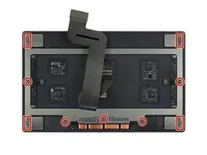
    • Check the alignment of the rubber vibration dampers, and adjust them as needed.

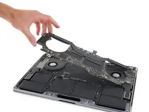
    • Feed the antenna cable bundle through the gap between the logic board and heat sink, and make sure it lines up correctly as you lower the board into place.

    • Verify that no cables get trapped under the board as you install it. Check each marked location carefully.

    Would be good to mention (at the end of instructions here) to pay special attention on reassembly that the Touch ID and power button cable does not slip under the logic board at the last moment7

    Wolf Naegeli -

Conclusion

To reassemble your device, follow these instructions in reverse order.

Jeff Suovanen

Member since: 06/08/13

427153 Reputation

0 comments