
Introduction
Use this guide to replace the microphone cable.
This guide requires the removal of the heat sink and logic board. Don't forget to follow our thermal paste application guide before you reinstall your heat sink.
-
-
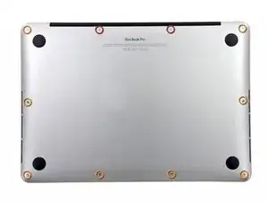
Remove the following ten screws securing the lower case to the upper case:
-
Two 2.3 mm P5 Pentalobe screws
-
Eight 3.0 mm P5 Pentalobe screws
-
-
-
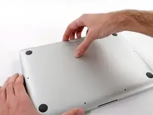
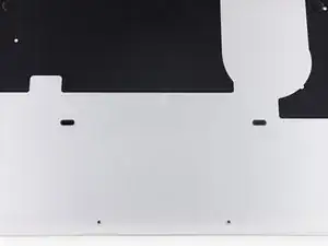
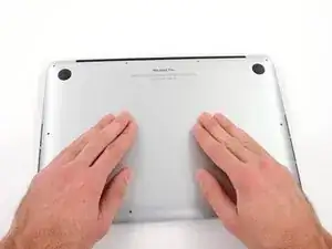
Wedge your fingers between the upper case and the lower case.
-
Gently pull the lower case away from the upper case to remove it.
-
-
-
Use the flat end of a spudger to lift the battery connector straight up out of its socket on the logic board.
-
-
-
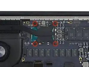
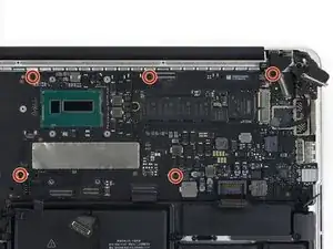
Remove the following screws securing the heat sink to the logic board:
-
One 2.7 mm T5 screw (silver)
-
Four T5 screws (black)
-
-
-
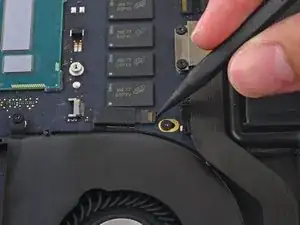
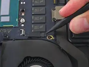
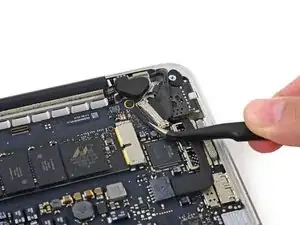
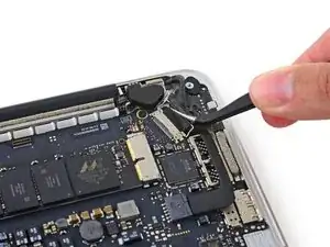
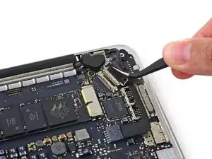
Use the tip of a spudger to push on either side of the the iSight camera cable connector to walk it out of its socket on the logic board.
-
-
-
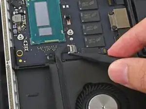
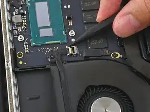
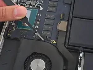
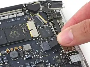
Use the tip of a spudger to flip the tab on the fan's ZIF connector.
-
Carefully pull the fan cable straight out of its socket.
-
-
-
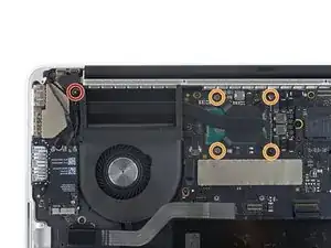
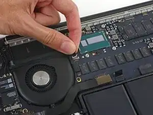
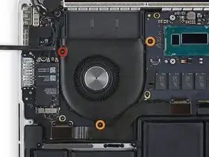
Remove the following screws securing the fan to the upper case:
-
One 5.0 mm T5 Torx screw
-
Two 3.6 mm T5 Torx screws
-
-
-
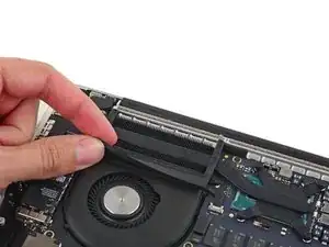
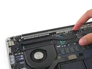
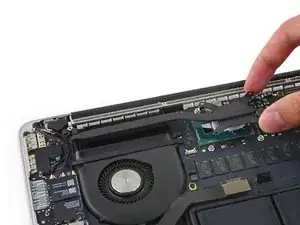
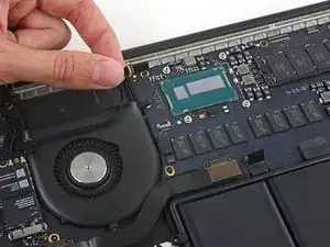
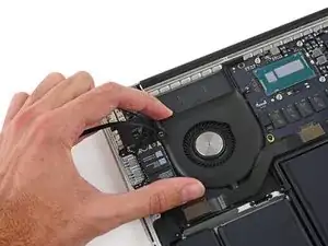
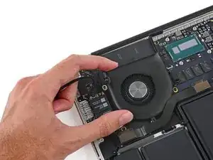
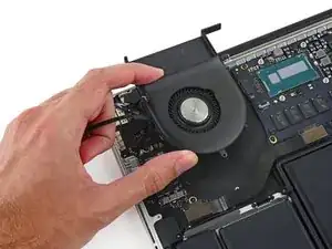
Lift the end of the fan closest to the display hinge and remove the fan from the upper case.
-
-
-
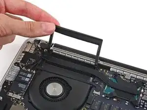
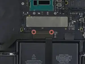
Remove the two 2.1 mm T5 Torx screws securing the I/O board cable bracket to the logic board.
-
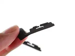
Remove the I/O board cable bracket.
-
-
-
Use the flat end of a spudger to pop the I/O board connector straight up off its socket on the logic board.
-
-
-
Use the tip of a spudger to lift the right speaker connector straight up out of its socket on the logic board.
-
-
-
With the tip of a spudger, push on either side of the I/O board connector to walk it out of its socket on the logic board.
-
-
-
Use the flat end of a spudger to disconnect the keyboard backlight cable and bend it up out of the way of the logic board.
-
-
-
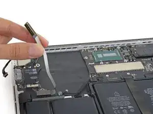
Grab the black plastic tab to flip the display cable connector open and pull it straight out of its socket on the logic board.
-
-
-
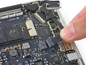
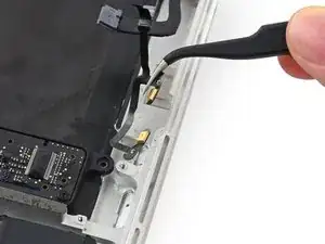
Wedge the flat end of a spudger under the left speaker cable near the connector and lift it straight up out of its socket and fold it out of the way.
-
-
-
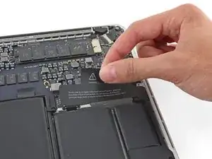
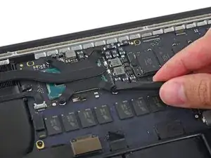
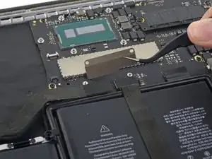
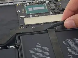
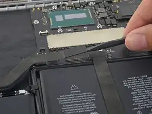
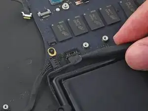
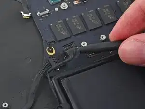
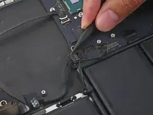
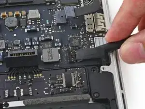
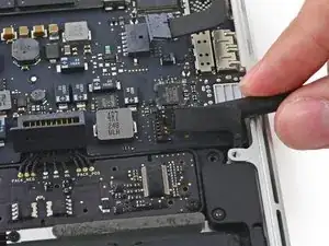
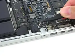
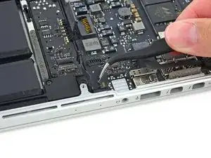
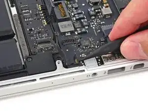
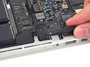
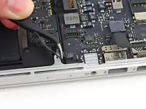
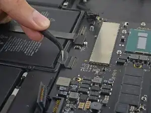
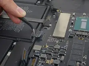
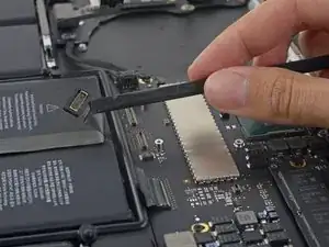
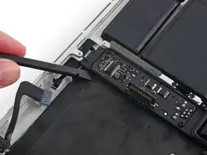
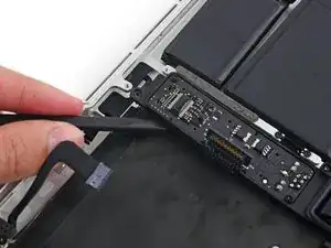
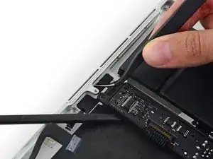
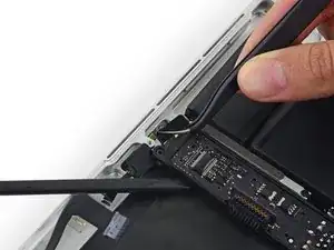
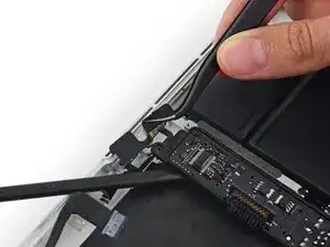
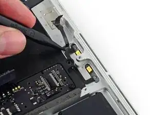
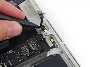
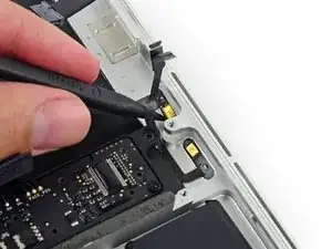
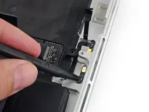
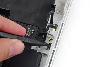
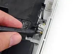
Use the tip of a spudger to flip the retaining tab on the microphone cable ZIF connector.
-
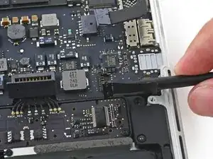
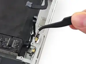
Pull the microphone cable out of its socket on the logic board.
-
-
-
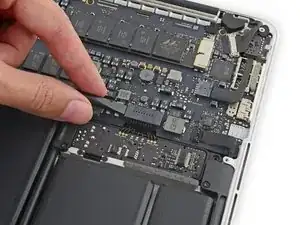
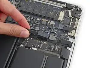
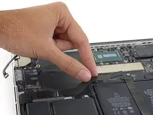
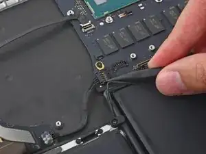
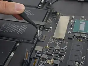
Use the flat end of a spudger to pop the trackpad connector straight up off its socket on the logic board.
-
Fold the cable out back over the battery to clear the way for the logic board.
-
-
-
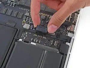
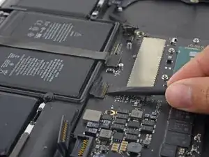
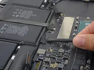
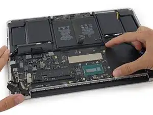
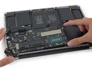
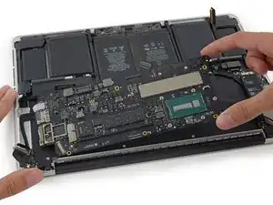
Lift the processor end of the logic board up slightly and pull it toward the fan recess to free the ports from the edge of the upper case.
-
Remove the logic board.
-
-
-
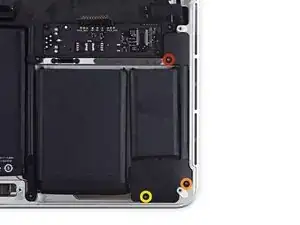
Remove the following screws securing the left speaker to the upper case:
-
One 5.7 mm T5 Torx screw
-
One 6.5 mm T5 Torx screw
-
One 3.8 mm T5 Torx screw
-
-
-
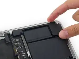
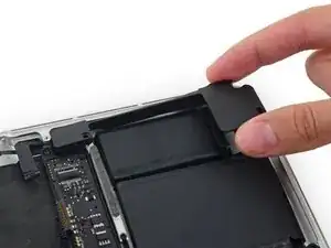
Lift the corner of the left speaker up and slide it toward the battery to remove it from the upper case.
-
-
-
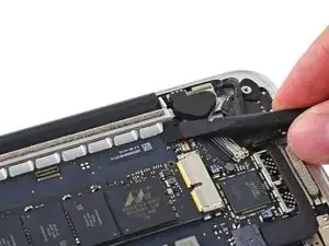
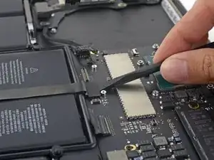
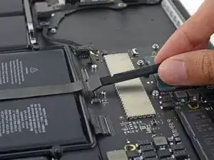
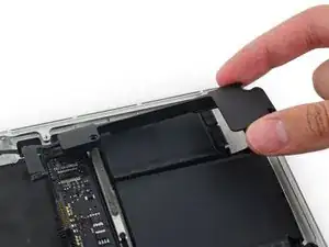
Insert the tip of a spudger under the battery-side portion of the rubber microphone cable cover to detach the adhesive there.
-
-
-
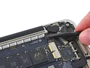
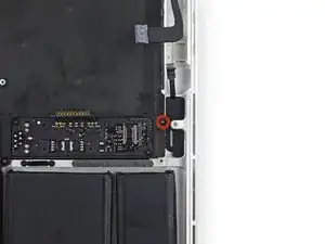
Use the flat end of a spudger to wedge the battery contact board up slightly to allow room to extract the dual microphone assembly.
-
-
-
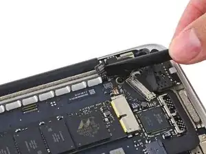
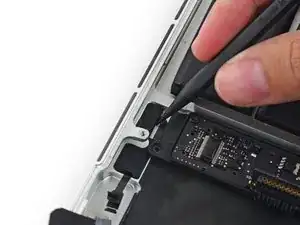
Insert the tip of a spudger underneath the connector end of the microphone ribbon cable and slide it toward the screw post to free that half from the upper case.
-
-
-
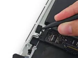
Insert the tip of a spudger under the battery-side portion of the microphone ribbon cable and slide it toward the screw post to free it from the upper case.
-
-
-
Pull the dual microphone cable assembly up and toward the logic board recess to remove it from the upper case.
-
To reassemble your device, follow these instructions in reverse order.
4 comments
Simply DISABLING the microphones can be done in 3 steps: #1, #2, #25, #26. No need to yank the logic board/fan and all that.
Many thanks for preparing / making this brilliant guide available. The mic in my Macbookpro failed for some reason and, using this guide I replaced it with a refurbished spare and saved myself $$. Every single step has been captured with specific additional detail / imagery where needed. It’s scary working with the tiny connectors but this guide gives you confidence it can be done / you can do it.
Nick Cassidy,
Where did you find a replacement? I have looked EVERYWHERE and can not find one.
Thanks!
破玩意儿,音量开到100听歌儿几个小时后绝逼带去售后换喇叭。
james -
For all the screws you use the P5 pentalobe screwdriver?
Carlos -
Pentalobe is only for the screws on the bottom cover. The Torx screw driver is for the remainder.
Fredrik -