Introduction
Use this guide to replace the headphone jack in your MacBook Pro 13" 2022 (M2).
If your battery is swollen, take appropriate precautions.
Some photos in this guide are from a different model and may contain slight visual discrepancies, but they won't affect the procedure.
-
-
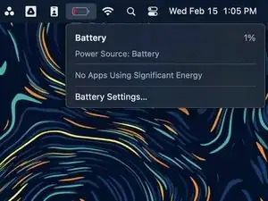
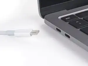
Unplug all cables and fully shut down your MacBook.
-
Close the lid and flip your MacBook over. Keep the lid closed until you've physically disconnected the battery.
-
-
-
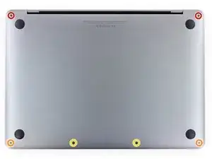
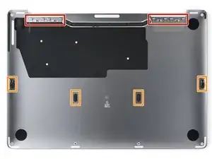
Use a P5 Pentalobe driver to remove the six screws securing the lower case:
-
Two 6.8 mm screws
-
Two 5.3 mm screws
-
Two 3.4 mm screws
-
-
-
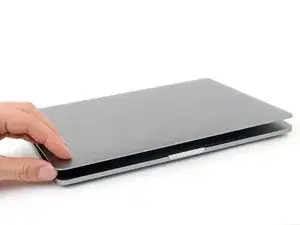
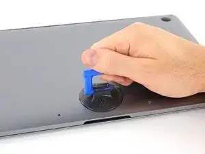
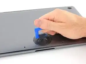
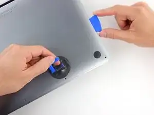
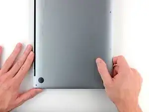
Apply a suction handle near the front edge of the lower case, between the screw holes.
-
Pull up on the suction handle to create a gap between the lower case and the frame.
-
-
-
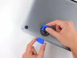
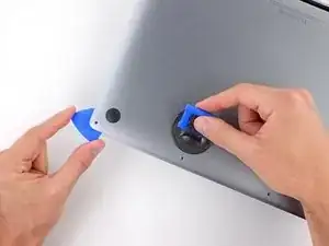
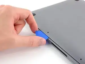
Insert an opening pick between the lower case and the frame.
-
Slide the pick around the left corner to release the first set of clips.
-
-
-
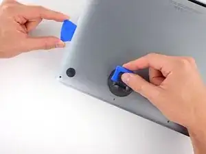
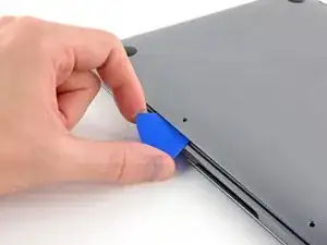
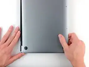
Slide your opening pick around the right corner to release the second set of clips securing the lower case.
-
-
-
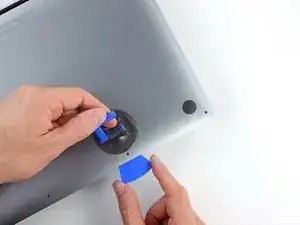
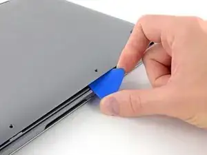
Insert your opening pick between the lower case and the frame near the middle left screw hole.
-
Firmly twist the pick until the clip releases.
-
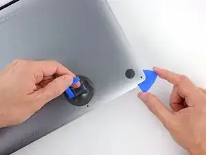
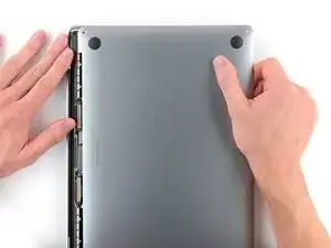
Repeat this procedure for the clip near the middle right screw hole.
-
-
-
Firmly pull the lower case away from the screen hinges to release the last clips securing it to the frame.
-
-
-
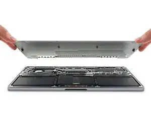
Remove the lower case.
-
Set it in place and align the sliding clips near the display hinges. Press down and slide the lower case toward the hinges.
-
Once the lower case is secured near the hinges, press down firmly to engage the remaining four clips.
-
-
-
Use blunt noise tweezers or your fingers to peel and remove the cover from the battery board, just above the middle battery cell.
-
-
-
Use blunt nose tweezers to gently peel back the pull tab covering the battery data connector.
-
-
-
Use the point of a spudger to flip up the small locking tab securing the battery data connector.
-
-
-
Use blunt nose tweezers or your fingers to grab the battery data cable pull tab and slide it straight out of its socket.
-
Move the cable to the left, out of the way of the battery board.
-
-
-
Use the flat end of your spudger to slightly lift the battery connector away from the battery board.
-
-
-
Use your T5 Torx driver to remove the two screws securing the left cable bracket to the logic board:
-
One 3.6 mm screw
-
One 2.6 mm screw
-
Remove the bracket.
-
-
-
Use the point of your spudger to pry up and disconnect the antenna cables from the logic board.
-
-
-
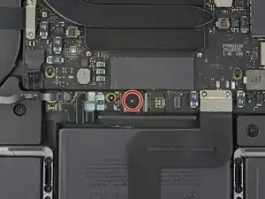
Use your T5 Torx driver to remove the 3.4 mm screw securing the antenna cables to the logic board.
-
-
-
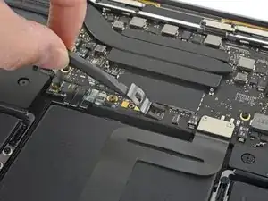
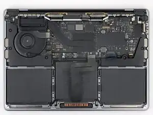
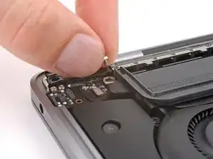
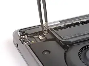
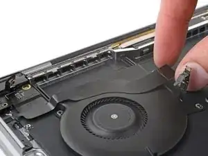
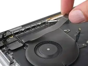
Use the point of a spudger to flip up the small locking tab securing the right speaker connector.
-
Grab the pull tab on the head of the cable and slide it straight out of its socket.
-
-
-
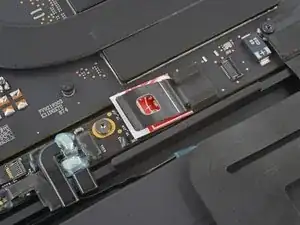
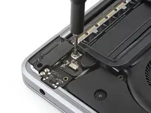
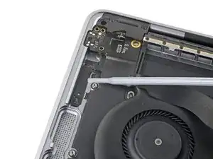
Use your T5 Torx driver to remove the two 1.9 mm screws securing the trackpad cable bracket.
-
Remove the bracket.
-
-
-
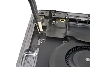
Use the flat end of your spudger to pry up and disconnect the trackpad cable from the logic board.
-
-
-
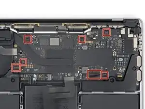
Disconnect the seven remaining ZIF connectors from the logic board by lifting their locking tabs and pulling them straight out of their sockets.
-
-
-
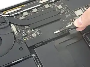
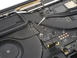
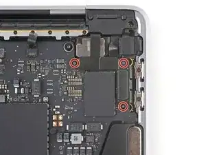
Use your T3 Torx driver to remove the three 1.4 mm screws securing the cable bracket to the top right of the logic board.
-
Remove the bracket.
-
-
-
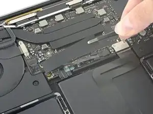
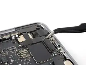
Use the point of your spudger to pry up and disconnect the Touch Bar press connector from the top right of the logic board.
-
Repeat this step for the lid angle sensor and the Thunderbolt ports press connectors.
-
-
-
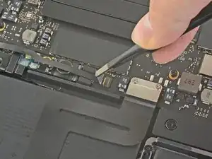
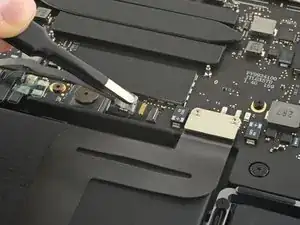
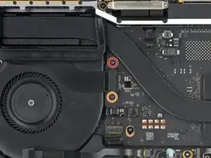
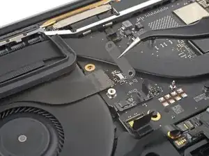
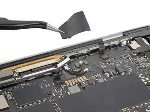
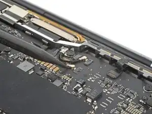
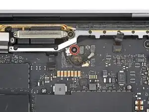
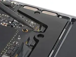
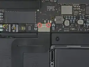
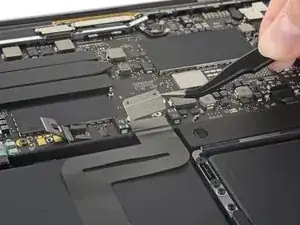
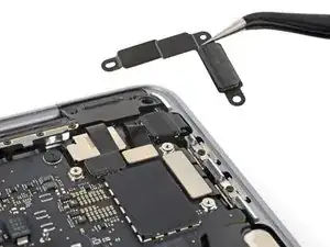
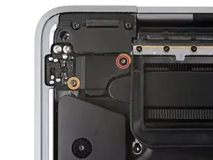
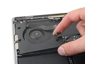
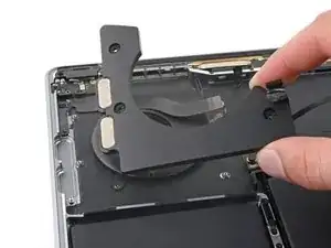
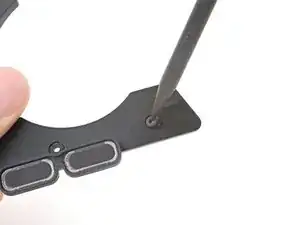
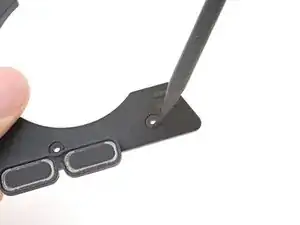
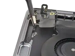
Use your T3 Torx driver to remove the two screws securing the cable cover near the headphone jack:
-
One 1.4 mm screw
-
One 4.9 mm screw
-
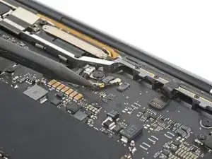
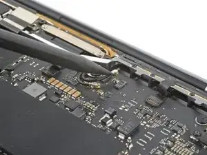
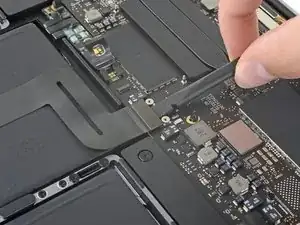
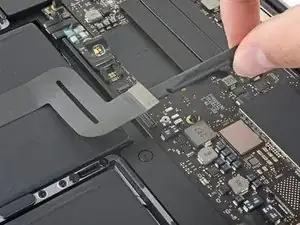
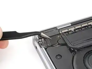
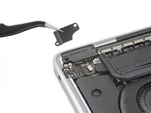
Remove the cover.
-
-
-
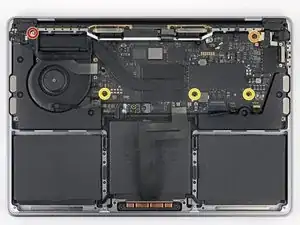
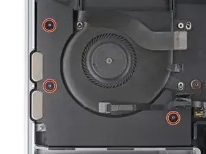
Remove the five screws securing the logic board:
-
One 3.0 mm hex head screw
-
One 3.7 mm T5 Torx screw
-
Three 3.3 mm T5 Torx screws
-
-
-
Thread the screw in using your fingertips.
-
Thread the screw in using blunt nose tweezers.
-
Use your T3 Torx driver to install the 1.4 mm screw into the hex head screw. Then, install the hex head screw using the T3 Torx driver. Finally, hold the hex head screw while you remove the 1.4 mm screw.
-
Once the hex head screw is threaded in a few turns, tighten it using your nut driver.
-
-
-
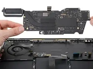
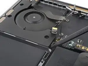
Insert the point of your spudger between the bottom left of the logic board and the left speaker assembly.
-
Pry up on the logic board until you can grab it with your fingers.
-
-
-
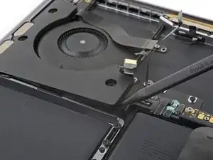
Grip the bottom left edge of the logic board.
-
Pull the logic board down and left to free it from the press connectors and antenna cables in the upper right corner.
-
Lift the logic board out of its recess, making sure not to catch on any loose cables.
-
-
-
Insert the point of your spudger between the right edge of the left speaker and the frame.
-
Pry the speaker out of its recess in the frame.
-
-
-
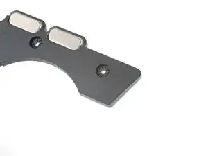
Orient each rubber spacer so the smooth side is poking out the underside of the speaker.
-
Insert one side of the spacer through the bottom of its screw hole.
-
Use the point of a spudger to press the spacer into its slot.
-
-
-
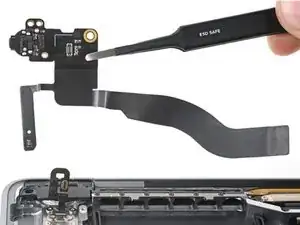
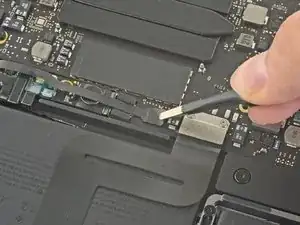
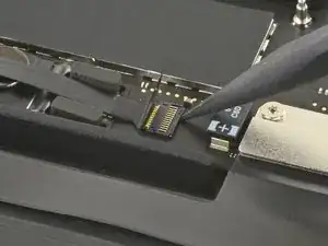
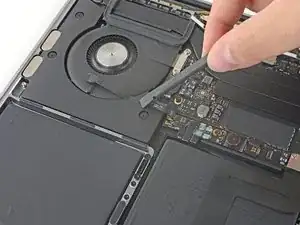
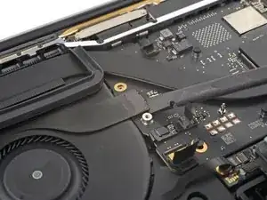
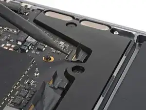
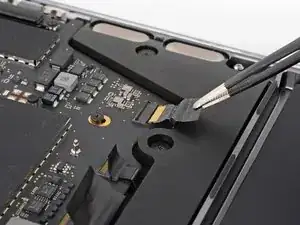
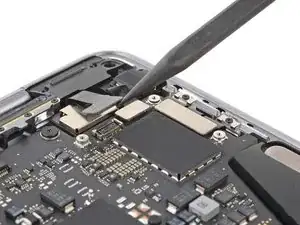
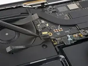
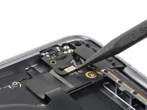
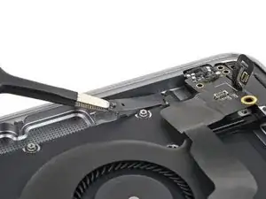
Use the point of your spudger to pry up and disconnect the press connector from the headphone jack board.
-
Reposition the cable away from the board.
-
-
-
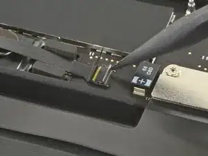
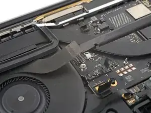
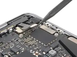
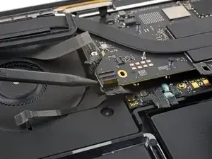
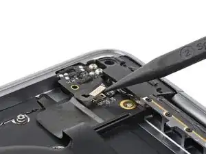
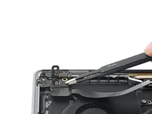
Apply highly-concentrated isopropyl alcohol (over 90%) to the section of cable under the headphone jack.
-
Wait one minute for the isopropyl alcohol to soften the adhesive.
-
-
-
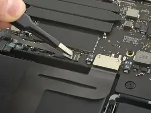
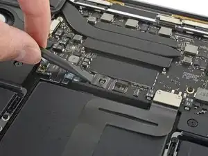
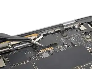
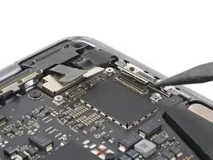
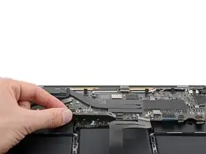
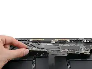
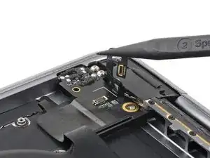
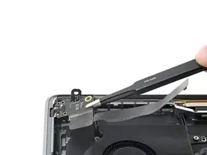
Use blunt nose tweezers to grab the upper section of cable adhered to the frame.
-
Slowly lift the cable straight up to loosen it from the frame.
-
Grab the bottom of the cable and peel it from the frame, making sure to avoid the circuitry on the cable.
-
-
-
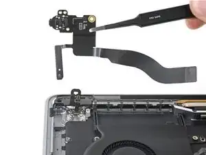
Grab the right edge of the headphone jack board.
-
Angle the board up and slide it out of its recess to remove it.
-
To reassemble your device, follow these instructions in reverse order.
Take your e-waste to an R2 or e-Stewards certified recycler.
Repair didn’t go as planned? Try some basic troubleshooting or search our Answers community for help.