Introduction

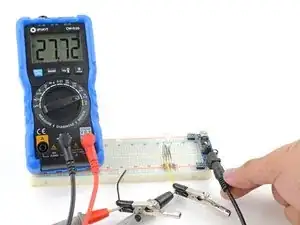
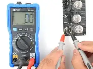
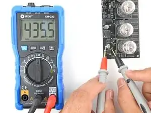
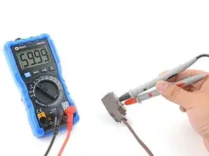
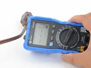
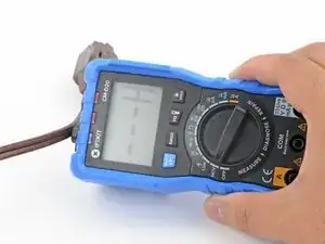
This guide shows how to use your multimeter to measure beyond voltage, resistance, and continuity. If you've mastered the basics and you're ready to learn more, this guide is for you!

This guide is written with the iFixit multimeter in mind. If you have a different multimeter, you may not have the same functionality and there may be slight operational differences. The fundamental concepts, however, will still be applicable.

    • Current describes the flow rate of electrons/holes at a particular point in a circuit. The SI unit of measurement for current is an Amp (A). Portable devices often operate in the low ranges of microamps (μA) or milliamps (mA).

    • You can use current measurements to help calculate a variety of power and energy estimations, such as how long a battery can power a device, or how much energy a device uses in a day.

    • Current measurements must be performed on a live circuit. If done improperly, you can damage the circuit and your multimeter, and risk electric shock. Take note of these precautions when you measure current:

    • Your multimeter acts like a short-circuit when it's in current measurement mode. Be very aware of what you touch with the multimeter probes to prevent unintentional short circuits, which can damage your circuit or the multimeter.

    • Power down the circuit while you set up. You can easily short something with your probes if you set up on a live circuit. This can damage your circuit and your multimeter.

    • Many multimeters will have a low and high current port, as they're protected by different fuses. The current limits are normally printed next to the port. If the current exceeds the limit for a short period of time, it will blow the associated fuse. If this happens to your iFixit multimeter, follow this guide to replace the fuse.

  1. KcTJPl4ZLx5YjQ6n
    KcTJPl4ZLx5YjQ6n
    BRBSEE5JUiX1IexQ
    • The next two steps show how to measure high (600mA-10A) current.

    • The iFixit multimeter's high current (10A) port fuse is soldered to the multimeter's motherboard. If you suspect the current measurement is higher than 10A, don't use the multimeter to make the measurement. Instead, use a higher rated current meter or a clamp meter.

    • Measuring amp-level current can be dangerous even at low voltage (12V) levels! Follow these precautions:

    • Be very aware of what the probes are touching and make sure they don't accidentally touch anything conductive.

    • Be careful not to touch any exposed circuitry. If there's a significant chance of exposure, cover the live circuit with insulating material or wear protective equipment such as insulating gloves.

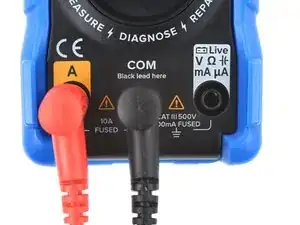
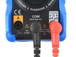
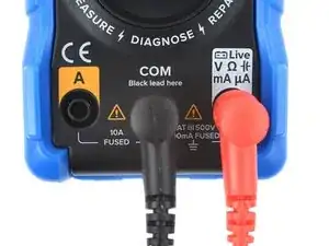
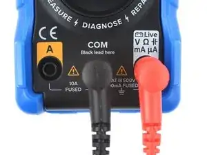
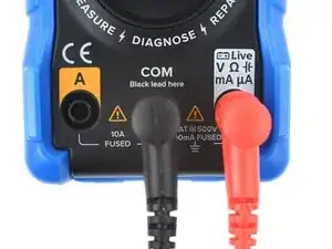
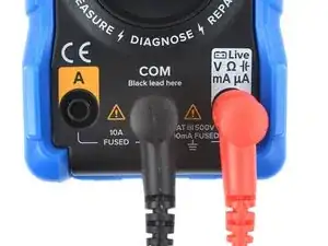
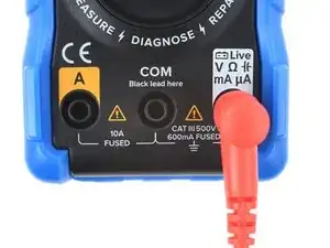
    • Plug the black lead into the COM port. Plug the red lead into the A port (the left port on the iFixit multimeter).

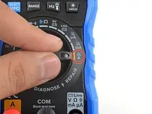
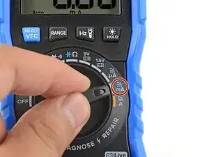
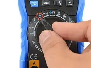
    • Turn the function dial to the amp A mode. If you're measuring Alternating Current (AC), press the blue select button to switch to AC mode.

  2. 6B5d3vnqYdTcwsMQ
    6B5d3vnqYdTcwsMQ
    ZwGkbiAZyhjMQvIN
    • Power down the circuit you're measuring.

    • Choose the point where you want to measure the current. You'll need to break the circuit at that point. This may mean snipping a wire, disconnecting a connector, or removing a jumper wire.

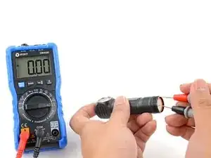
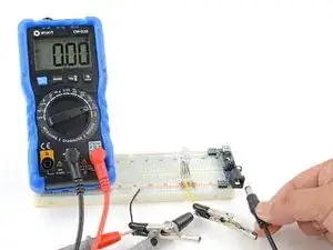
    • Connect the multimeter in-line with the circuit by touching the probes to the ends of the broken circuit. If possible, use alligator clips to hold the probes to the ends.

    • The polarity of the probes somewhat matters. The multimeter will measure current flowing into the red probe and out the black probe. If you reverse the probes, it will show a negative value on the multimeter, but it won't damage the meter.

    • Confirm that the probes are only touching what they should and nothing else.

    • Check to make sure the circuit isn't accidentally touching you or anything conductive that may short it.

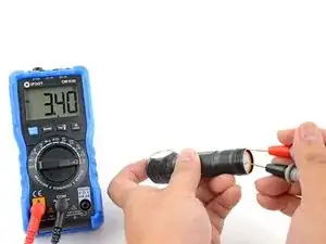
    • Power on the circuit and make your measurement.

  3. GJ2aR3JIXNucXONT
    GJ2aR3JIXNucXONT
    UvPSadwnQmAKFmLd
    cDTRQVigMLmKLtG5
    • The next two steps show how to measure low (<600 mA) current.

    • The iFixit multimeter's low current port has a 600mA limit. If you suspect the measurement will be above that, use the high current measuring method first.

    • Plug the black lead into the COM port. Plug the red lead into the mA port (the right port on the iFixit multimeter).

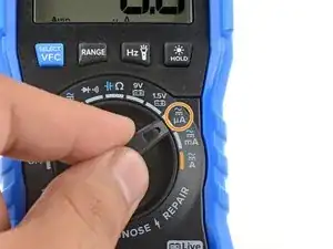
    • Turn the function dial to the milliamp mA mode. If you're measuring Alternating Current (AC), press the blue select button to switch to AC mode.

    • You can also measure in the microamp μA mode if you know you're measuring minute amounts of current. This changes the measurement range and gives you more precision at the μA range. Even if you exceed that range, it won't damage your multimeter—as long as you don't exceed the port limit (600mA).

  4. EHZEMSvtgHnBZjVc
    EHZEMSvtgHnBZjVc
    vdhQpqouHKcvjbOj
    • Power down the circuit you're measuring.

    • Choose the point where you want to measure the current. You'll need to break the circuit at that point. This may mean snipping a wire, disconnecting a connector, or removing a connecting jumper wire.

    • Connect the multimeter in-line with the circuit by touching the probes to the ends of the broken circuit. If possible, use alligator clips to hold the probes to the ends.

    • The polarity of the probes somewhat matters. The multimeter will measure current flowing into the red probe and out the black probe. If you reverse the probes, it will show a negative value on the multimeter, but it won't damage the meter.

    • Confirm that the probes are only touching what they should and nothing else.

    • Make sure the circuit isn't accidentally touching you or anything conductive that may short it.

    • Power on the circuit and make your measurement.

    • A capacitor is a component that stores electrical energy. It's like a low capacity, fast charging battery—except a battery stores energy via an electrochemical process, whereas capacitors store energy via electrical fields.

    • Capacitors are often used to store bursts of energy and filter/smooth out voltage fluctuations. Most circuit boards will have tiny surface-mount capacitors, while power supplies will have bigger cylindrical ones.

    • Thumb-sized capacitors can store enough energy to pose a risk of electric shock. Use a capacitor discharge tool to safely discharge larger capacitors.

    • Capacitance is a measurement of how much a capacitor can store at a given voltage. The SI unit of measurement for capacitance is a Farad (F). Most capacitors have a nF (nanofarad) or μF (microfarad) capacity.

    • Larger capacitors such as electrolytic capacitors are polarized, meaning they should only be connected in a specific direction. If they're used in reverse for extended periods of time, they will fail and often burst.

    • When a capacitor fails, it usually short-circuits. The dielectric material which insulates the layers breaks down and the layers conduct, shorting the capacitor. A working capacitor should never have a resistance measurement of less than a few kilohms.

    • The multimeter measures capacitance by charging the capacitor with constant current, recording how long it takes for the capacitor to charge/discharge, and calculating the capacitance value with an equation. Depending on the size of the capacitor, the multimeter may not give a very accurate reading.

    • You'll often need to decouple the capacitor from the circuit in order to measure it. Capacitors are commonly integrated in parallel to other components in a circuit, making direct measurement difficult. To decouple the capacitor, desolder/disconnect one end of the capacitor from the circuit.

  5. AYTgUuXAWBQBGJq4
    AYTgUuXAWBQBGJq4
    pi1dFG6fveMY6vqq
    3RnPNFgJwrF6QnVx
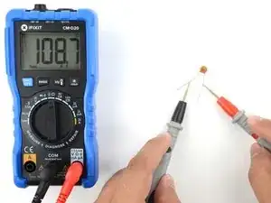
    • This step shows how to measure small ceramic or film capacitors. These capacitors are normally flat, with a body that's smaller than 5 mm.

    • Plug the black lead into the COM port. Plug the red lead into the right port.

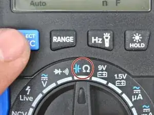
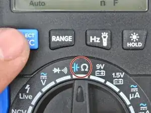
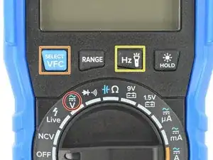
    • Turn the function dial to the resistance/capacitance mode and press the blue select button to toggle on the capacitance mode.

    • Power down the circuit you're measuring, if you're measuring the capacitor while it's still connected to the circuit.

    • Touch the probes to each end of the capacitor to make a measurement.

    • If you're measuring a capacitor on a circuit board and you're not getting a proper reading, the capacitor may be in parallel with other circuit components. You'll need to desolder or disconnect one end before measuring the capacitor.

  6. xfZ6U1tyJrtlEK1s
    xfZ6U1tyJrtlEK1s
    kFePeUY3RTSyLiCp
    JDFXMoileGPWFdlr
    • The next two steps show how to safely measure larger electrolytic capacitors. These capacitors look like small cylinders. The iFixit multimeter can only measure capacitance up to ~100mF (millifarads).

    • Plug the black lead into the COM port. Plug the red lead into the right port.

    • Power down the circuit you're measuring, if you're measuring the capacitor while it's still connected to the circuit.

    • Make sure the capacitor is sufficiently discharged:

    • Turn the function dial to the DC volt mode.

    • Carefully touch the probes to the capacitor's leads/pads to measure voltage. Treat the circuit as a live circuit and be careful not to touch anything else with your probes.

    • Make sure the capacitor voltage is 10V or less. If it isn't, wait a minute to let the capacitor self-discharge, or use a capacitor discharge tool to discharge the capacitor.

    • As you measure the capacitor's voltage, the multimeter may slowly charge the capacitor up. Don't measure the capacitor for too long to prevent this from happening.

  7. VNfdk4roOwpMtsAl
    VNfdk4roOwpMtsAl
    sTuxWOidOdejrxGv
    • Once you've ensured that the capacitor is sufficiently discharged, you can measure its capacitance.

    • Turn the function dial to the resistance/capacitance mode and press the blue select button to toggle on the capacitance mode.

    • Touch the probes to each end of the capacitor to make a measurement.

    • Even though the electrolytic capacitor may be polarized, it doesn't matter how you connect the probes during the measurement.

    • If you're measuring a capacitor on a circuit board and you're not getting a proper reading, the capacitor may be in parallel with other circuit components. You'll need to desolder or disconnect one end before measuring the capacitor.

    • A diode is a component that allows current to easily flow through it in one direction (from the anode to the cathode). Diodes are commonly found in power supplies and converters.

    • A light emitting diode (LED) is a popular sub-category of diodes that light up as current flows through it. LEDs work only when they're connected in the correct orientation.

    • A diode's cathode (or "output" end) is marked with a white band. An LED's cathode is normally the short lead, and the plastic bulb has a flat edge.

    • In order for the diode to turn on and let current through, the voltage at the anode (input) has to surpass a threshold. This is known as the forward bias or forward threshold voltage. The threshold voltage can be 0.6V-5V.

    • If voltage is applied to the cathode (output) end, the diode will resist current flow up to a certain voltage limit. This is known as the breakdown voltage. If the voltage surpasses the breakdown voltage, the diode will break down and act like a short circuit.

    • When this happens, the diode is usually toast. Zener diodes, however, are specifically designed to breakdown repeatedly without being damaged.

    • Diodes (including LEDs) can break either as an open-circuit or a short-circuit. If too much current flows through the "forward" direction, the diode will burn out like a fuse, creating an open-circuit. If the diode is accidentally installed in reverse, it may short-circuit.

  8. u2aBQxqpJktFieIn
    u2aBQxqpJktFieIn
    ohlu3BcBFNonaUNU
    • The next two steps show how to use your multimeter to test diodes and LEDs.

    • Plug the black lead into the COM port. Plug the red lead into the right port.

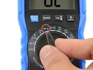
    • Turn the function dial to the diode/continuity mode.

    • The iFixit multimeter automatically selects the diode mode when you touch the probes to a diode.

  9. wAnDiZGAuAXSfIWK
    wAnDiZGAuAXSfIWK
    AmDrShUmfXdSHcwt
    Q4B4EyuVfiSchtu2
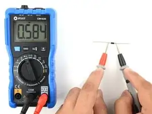
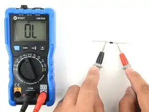
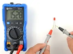
    • Touch the red probe to the anode, "input", or unmarked end of the diode. If you're testing an LED, touch the longer lead.

    • Touch the black probe to the cathode, "output", or marked end of the diode. If you're testing an LED, touch the shorter lead (or the lead next to the flat side of the LED).

    • The multimeter should show a non-zero voltage, which is the forward bias voltage.

    • If the multimeter reads 0L or 0V, the diode is burned out or short-circuited, respectively.

    • Reverse the probes so they touch the opposite ends of the diode.

    • The multimeter should show 0L, which stands for open circuit.

    • If the multimeter shows anything other than open circuit and the diode isn't connected to circuitry, the diode is defective.

  10. kqotCZTIqIJMWenW
    kqotCZTIqIJMWenW
    DRNYGZZKNyenSZ1q
    • The next two steps explain how to measure frequency with your multimeter.

    • The frequency functionality measures the dominant frequency in an AC circuit. If the circuit has complex AC signals or noisy signals, the multimeter may not measure the frequency accurately.

    • Plug the black lead into the COM port. Plug the red lead into the right port.

    • Switch the multimeter to the AC Hz mode:

    • Turn the function dial to the Volts mode.

    • Press the blue Select button to switch to AC volts.

    • Press the Hz button to toggle the frequency measurement mode.

  11. nPmwNKItOXZBZHJu
    • You'll be testing a live circuit. Be very careful not to touch any exposed circuitry. If there's a significant chance of exposure, cover the live circuit with insulating material or wear protective equipment such as insulating gloves.

    • Be careful as you position your probes, making sure they don't accidentally short anything. If possible, power off the circuit while you set up.

    • Touch the probes across the AC source and make a measurement.

    • If you're measuring something that's electrically noisy (such as a compressor motor), you can toggle the Variable Frequency Controller (VFC) function to filter high frequency noise out. This will reduce the precision of the measurement.

    • To toggle the VCF mode on/off while you're measuring AC frequency, hold the blue Select/VFC button for two seconds.

  12. sRmEBdgXkYAFmR6Q
    sRmEBdgXkYAFmR6Q
    vGHfYGY2v34A5NOF
    • The Non-Contact Voltage (NCV) function allows you to sense AC power in a circuit or wire without having to electrically connect to it.

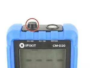
    • The NCV sensor sits inside the plastic nub at the top of the iFixit multimeter. The metal strip inside acts as an "antenna" that detects the electromagnetic field generated by an AC source. This field gets stronger the closer it is to the source.

    • The NCV won't detect whether there's DC power in a circuit or wire.

    • The NCV may not always detect a live circuit or wire. For safety reasons, never rely on the NCV as your sole point of information if you're working above 20V AC.

    • The iFixit multimeter's NCV function detects ~45V AC and above.

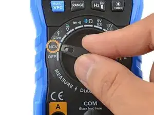
    • To use the NCV function, turn the function dial to the NCV mode.

  13. oupGLEX6j4I3WvIJ
    oupGLEX6j4I3WvIJ
    bOhMiWWRCUEVp2EY
    RraqhLOg5q3Lu1id
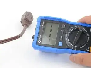
    • Move the NCV sensor so that it's close to the wire or circuit. If there's live AC, the multimeter will begin beeping and the top indicator LEDs will light up.

    • If the NCV detects ~45-100V, a single green indicator LED will light up, and the screen will display "L".

    • If the NCV detects above 100V, two red indicator LEDs will light up, and the screen will display "H".

    • Most of the time, you can detect which wire in a power cable is live by touching the NCV sensor along each edge of the cable.

  14. AlJnIQv2xVkNThNI
    AlJnIQv2xVkNThNI
    cI6fbZ42DPLUTDYF
    5drY14IFlOdVcK61
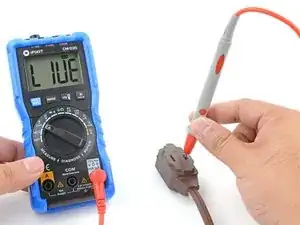
    • The Live Wire function determines which wire in a bundle is live by using a single direct connection. You can use this to make sure an outlet is properly wired.

    • This function operates similarly to the Non-Contact Voltage (NCV) function, as it detects the electromagnetic field to determine whether a wire is live or not. The difference is that the Live Wire function uses a test probe to shift the testing into the multimeter. This allows you to clearly distinguish which wire in a bundle is live.

    • Don't use the Live Wire function as a NCV tester—it isn't sensitive enough to reliably report the presence of AC voltage. Use the Live Wire function to determine correct wiring, not whether there's AC power or not.

    • Plug a probe into the right-most port of the multimeter.

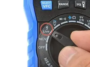
    • Turn the function dial to the Live mode.

    • Touch the probe to the wire you want to test.

    • If the wire is live, the multimeter will beep and display "LIVE".

    • If the Live Wire function doesn't detect any live wires when you expect it to, try grasping the multimeter with your free hand. This helps with capacitive coupling, which Live Wire uses to function.

Conclusion

For more electronics skills guides, click here.
Arthur Shi

Member since: 03/01/18

248652 Reputation

0 comments