Introduction

This repair guide was authored by the iFixit staff and hasn’t been endorsed by Google. Learn more about our repair guides here.

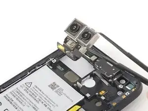
Use this guide to remove or replace the rear-facing cameras on your Google Pixel 4.

Caution: Google warns that disassembly of the front laser assembly could result in hazardous exposure to invisible infrared laser emissions. Read their safety warnings here.

  1. VbMFcJIqjkF2oOxL
    VbMFcJIqjkF2oOxL
    T2OsClj3mdTufoeA
    Jb5M1CAKCkCmZejc
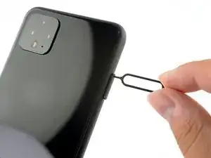
    • Insert a SIM eject tool, bit, or a straightened paper clip into the small hole on the SIM card tray on the left edge of the phone.

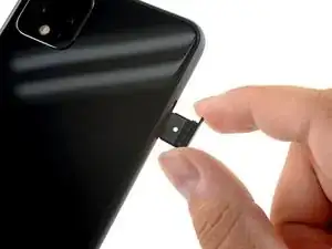
    • Press firmly to eject the tray.

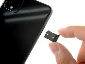
    • Remove the SIM card tray.

  2. Hvp1kuHwJo1AClCp
    • Prepare an iOpener and apply it to the bottom edge of the back panel for one minute.

    • A hair dryer, heat gun, or hot plate may also be used, but be careful not to overheat the phone—the display and internal battery are both susceptible to heat damage.

  3. VK4rWKHPMxSBgjeI
    VK4rWKHPMxSBgjeI
    GS4NhjEZM3SCXJcR
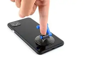
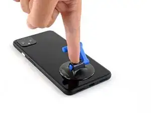
    • Apply a suction cup to the heated edge of the back panel by pressing down on it to create suction, as close to the edge as possible.

    • If your back glass is badly cracked, covering it with a layer of clear packing tape may allow the suction cup to adhere. Alternatively, very strong tape may be used instead of the suction cup. If all else fails, you can superglue the suction cup to the broken panel.

  4. mkgNQMFVCGsIjSWI
    mkgNQMFVCGsIjSWI
    ZcuoIwCBSbZQv1Jp
    • Pull up on the suction cup with strong, steady force to create a gap between the back panel and the frame.

    • Depending on the age of your phone, this may be difficult. If you are having trouble, apply more heat to the edge and try again.

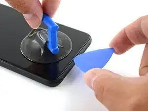
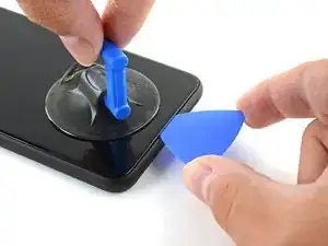
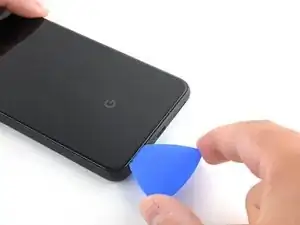
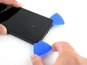
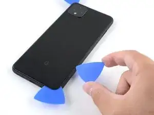
    • Insert the point of an opening pick into the gap.

  5. JPn1p4UL3KeHgTlm
    JPn1p4UL3KeHgTlm
    rerDsh5OJUS5DXft
    pq3vfvBe5v5htEJY
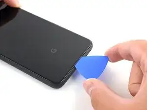
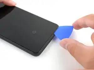
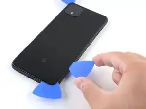
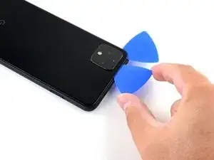
    • Slide the opening pick across the bottom towards the left corner to slice the adhesive.

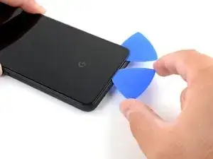
    • With the pick still inserted, slide it from the bottom left corner over to the bottom right corner to completely slice the bottom side adhesive.

    • Leave the pick inserted in the bottom right corner to prevent the adhesive from re-sealing.

  6. bmjILIENBtpPcpxn
    • Prepare an iOpener and apply it on the left edge of the phone for one minute.

  7. GQ32GFimDFPnCaIN
    GQ32GFimDFPnCaIN
    KwMHik5nQYlWV3HD
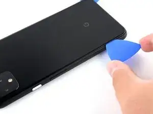
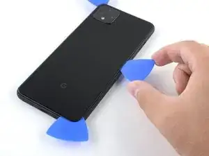
    • Insert a second opening pick underneath the back panel directly over the charge port.

    • Slide the opening pick to the bottom left corner of the phone.

  8. 3wRXCsDVIiReHwDt
    3wRXCsDVIiReHwDt
    TsAtoOUWx5OUtfJw
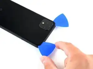
    • Slide the opening pick around the bottom left corner and across the left side of the phone to slice the adhesive.

    • The adhesive can be very gummy. Push the pick in and out in a sawing motion to help with slicing.

    • Stop when you reach the top left corner, near the camera, and leave the pick inserted.

  9. qPt1cI1qIYhrYhrk
    • Prepare an iOpener and apply it on the right edge of the phone for one minute.

  10. 3MaLYKdcXwMGfmHm
    3MaLYKdcXwMGfmHm
    nNHbQECIIHKXCkeA
    dgKAYchvRQfbG4ZJ
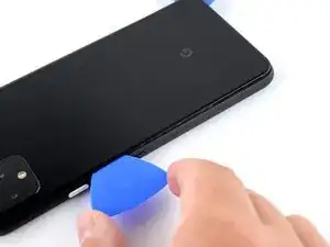
    • With the first two opening picks still in place, insert a third pick on the lower part of the righthand side.

    • Slide the opening pick up towards the top of the phone, slicing the right side's adhesive.

    • Stop when you reach the top right corner, and leave the pick inserted.

  11. pdXuWBOPnOHID4vo
    pdXuWBOPnOHID4vo
    I1Y2GTUYJV4tftII
    • Slide the third opening pick around the top right corner and across the top side of the phone, slicing the final strip of adhesive.

  12. HySfZPvhGRSUENZS
    HySfZPvhGRSUENZS
    54ZsgXBi4YYA6vBS
    YMgGdiVcyxhx52e1
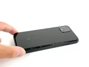
    • Once you have sliced around the perimeter of the phone, carefully lift the right edge of the back cover, opening it like a book.

    • Do not try to pull the panel all the way off yet, as it is still connected to the phone.

  13. iFNKHEbN5C5UEQkS
    iFNKHEbN5C5UEQkS
    B5L3GJWi4AWfOxaI
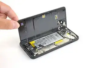
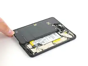
    • Continue swinging open the back panel until you can rest it on the left edge the phone, being careful not to put any stress on the attached ribbon cable.

    • During reassembly, this is a good point to power on your phone and test all functions before re-sealing the back panel. Be sure to power your phone back down completely before you continue working.

    At this point I suggest taking a photo of what you're seeing in there. This way you can make sure you put it all back the way it was when you're done.

    Brian Wood -

  14. cDEhvBgNJQUZJ2NE
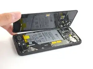
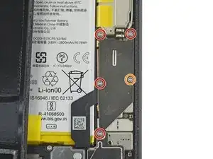
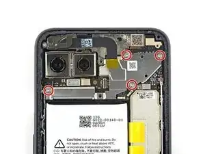
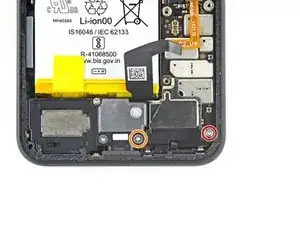
    • Remove the five T3 Torx screws securing the battery connector shield:

    • Four 4.0 mm screws

    • One 2.1 mm screw

    • Throughout this repair, keep track of each screw and make sure it goes back exactly where it came from.

    Does anyone know where I can get a replacement T3 - 2.1mm screw (the one circled in orange)? I lost this screw during the battery replacement. Had it, dogs fought, had to get up to break it up, and couldn’t find it. I swore I put it on the mat, but I couldn’t find it when I got back to the table. :(

    Nikki Chan -

  15. DpgvSry4M16dxYBf
    DpgvSry4M16dxYBf
    Tgut2yL1UUMP6SWV
    • Use a pair of tweezers to remove the battery connector shield.

  16. A34sTTTFGUNelCdO
    A34sTTTFGUNelCdO
    SBgRCm6ApbKbQuCr
    • Whenever you use the spudger near the battery, be very careful not to puncture the battery.

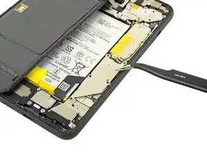
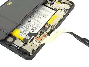
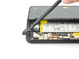
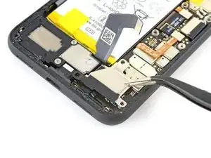
    • Using the pointed end of a spudger, pry the battery connector straight up from the motherboard to disconnect the battery.

    • To re-attach press connectors like this one, carefully align and press down on one side until it clicks into place, then repeat on the other side. Do not press down on the middle. If the connector is misaligned, the pins can bend, causing permanent damage.

  17. aSUOVtDFdAFw6ufa
    aSUOVtDFdAFw6ufa
    E22f6ZaNgbVi2xET
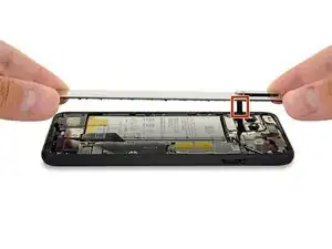
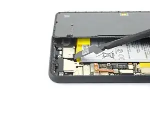
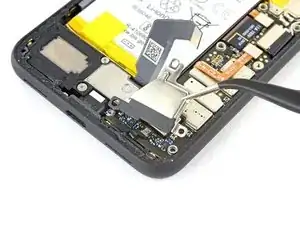
    • Using the flat end of a spudger, gently fold the battery cable over so it doesn't accidentally make contact during the rest of your repairs.

  18. XhJoRsZlHgH4g5iJ
    • Use a T3 Torx driver to remove the two 4 mm screws securing the back panel connector cover.

  19. LouDYcubQQ312jgD
    LouDYcubQQ312jgD
    sVhpSIsBpW1NlJCT
    • Use a pair of tweezers to remove the back panel connector cover.

  20. HmoWeEMDomqaJL4d
    HmoWeEMDomqaJL4d
    jhUrNSsNsSZVYYNb
    • Using the pointed end of a spudger, pry up and disconnect the back panel connector.

  21. 2XIeuefUddCBWJBf
    • Remove the back panel.

    • During reassembly, follow this guide to install custom-cut adhesives for your device.

    • Follow this guide if you are using a pre-cut adhesive card.

    Why does the kit not come with the back panel adhesive?

    It's not cheap to get the full kit, and it seems like it's such a small thing to include.

    I ended up re-using the existing back panel adhesive and now a bit worried that it's not as strong and I will have issues with water or moisture getting into the device more easily.

    Mike Y -

  22. dbf1sqAJqNNaLrNA
    • Use a T3 Torx driver to remove the four 4 mm screws securing the camera connector cover.

    left-most screw appears to be t4, not t3

    Mark Schierbecker -

  23. OtZmf5EsmL1ZJHor
    OtZmf5EsmL1ZJHor
    QbM6tCKlBN4lc3kd
    6VhpoKZhL5eZ5Via
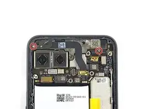
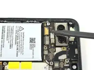
    • Using a pair of tweezers, tilt the camera cover up and slide it out of the retaining slot on the upper right corner of the phone to remove.

  24. TqqAOgH4IDoWuSth
    TqqAOgH4IDoWuSth
    gddsCQMWobKDIfkR
    srTJJprt1apYv4GO
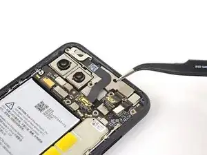
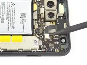
    • Using the pointed end of a spudger, pry the camera and sensor connectors straight up from the motherboard.

  25. yXvWySNvnucNyVIL
    yXvWySNvnucNyVIL
    VOOtTTYlqDDEtl3F
    • Disconnect the laser module connector.

  26. 5UxXMgxAwWkBgSYs
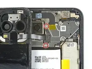
    • Use a T3 Torx driver to remove the two 2.4 mm screws securing the front camera and sensor assembly.

  27. n6qub1AOFWBoeWJp
    n6qub1AOFWBoeWJp
    NIoBPSfWUORaUjQj
    T4bpklZD6Kcangde
    • Use a pair of tweezers to remove the front camera and sensor assembly.

    I have done the whole step twice with two different (aftermarket) cameras on a Google Pixel 4 and the first one didn’t work at all and the second one worked perfectly good but then stopped working after restarting the phone. Why? And the faceID doesn’t work when the whole thing is replaced so I put the old one back so I can use the faceID. Why did the front camera work perfectly untill we restarted the phone and then stopped working???

    Mert Köroğlu -

    Maybe Google’s face ID works the same as Apple’s fingerprint or face ID module, they are bound with motherboards for security reasons.

    FROD Yeh -

  28. CWNKjmhJAmXJGoMe
    • Remove the two T3 Torx screws securing the vibration motor shield:

    • One 4.2 mm screw

    • One 4.4 mm shouldered screw

  29. YuLH6ehBkfrgOZwd
    YuLH6ehBkfrgOZwd
    WRBL2CQgeljisWis
    • Use a pair of tweezers to remove the vibration motor shield.

  30. y6fVteTjIHF2I26m
    y6fVteTjIHF2I26m
    c4PVSD4ZQu2Won1l
    XuOlRjKJJSuFlqsA
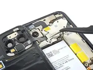
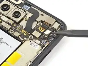
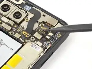
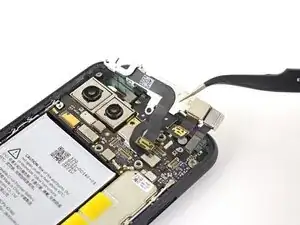
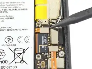
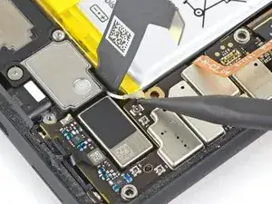
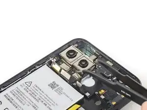
    • Use the pointed end of a spudger to disconnect the two rear-facing camera connectors from the motherboard.

  31. CxFfsiTvEY5nOyG1
    CxFfsiTvEY5nOyG1
    54nFPypoq3FIXYax
    IOPVhArW5RkAIdhD
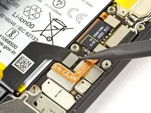
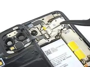
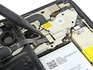
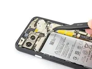
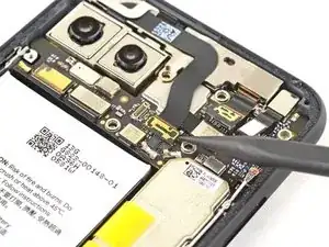
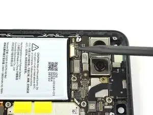
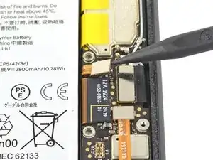
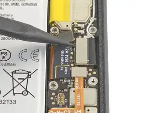
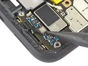
    • Disconnect the side buttons connector from the motherboard.

    • Disconnect the earpiece speaker connector from the motherboard.

  32. NZnLinrKa5hfrdcL
    NZnLinrKa5hfrdcL
    tCHUdMbs5I34yIJx
    ZEJIpvEeNQVQeBDk
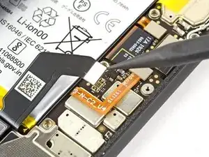
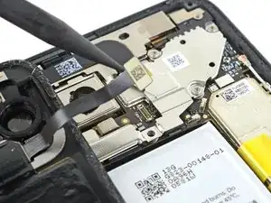
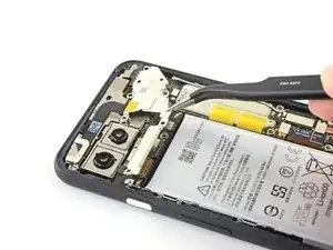
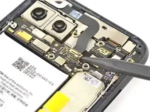
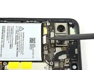
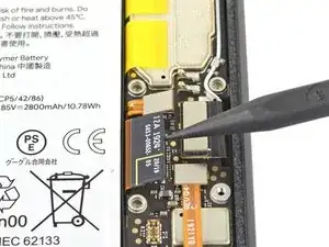
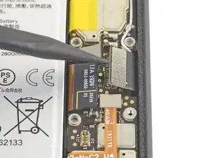
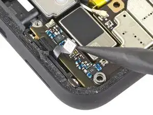
    • Disconnect the left grip sensor connector from the motherboard.

    • Disconnect the charge port connector from the motherboard.

  33. 4EIOc1QE2yQOZ2Il
    4EIOc1QE2yQOZ2Il
    sAmDk1vRXELFyTdo
    APAVHVoYRc2qOtvE
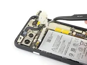
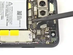
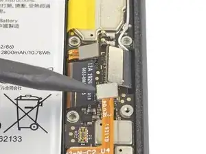
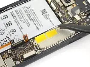
    • Disconnect the display connector from the motherboard.

    • Disconnect the right grip sensor connector from the motherboard.

  34. l6tHBFrMAcevpcZi
    l6tHBFrMAcevpcZi
    bkBDQ6CenFdm3mWq
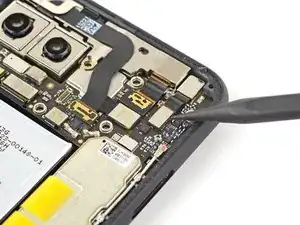
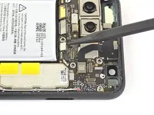
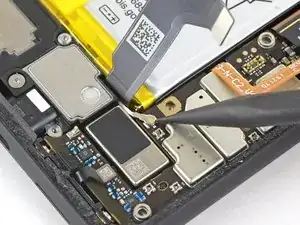
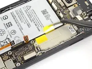
    • Use a pair of tweezers to grip the metal clip and pull the connector straight up off of the motherboard

    • You can also a spudger and pry up gently to unclip the bottom antenna connector from the motherboard.

  35. eBZbqUZWgsqUyZv5
    eBZbqUZWgsqUyZv5
    ISOCAryAoAY3p2F1
    • Disconnect the bottom microphone connector from the motherboard.

  36. IpFWnEmolCaWE5cB
    IpFWnEmolCaWE5cB
    K2JPXVaixwPiOldB
    3EXDUOFLGjFV3qHN
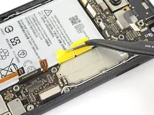
    • Gently pry back—but don't remove—the two battery adhesive pull tabs lightly adhered to the motherboard.

  37. tIRlLlJQdTZVwUGq
    tIRlLlJQdTZVwUGq
    aLrU516O2LDLfW5W
    • Using a spudger, pivot the top end of the motherboard up and out of the phone's frame.

  38. gpFP5rLUPklkj61D
    gpFP5rLUPklkj61D
    cBA4sERVddsWiMe1
    OCJZ6SqbEarcUnxV
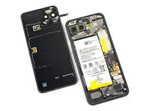
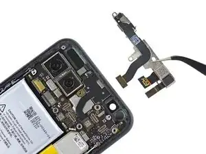
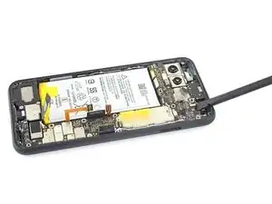
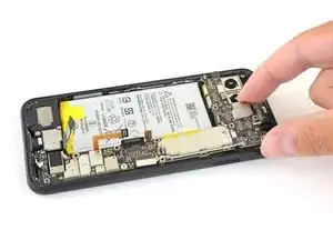
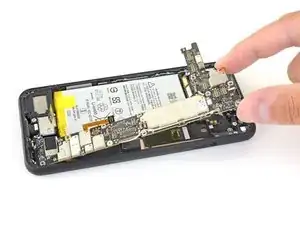
    • Slowly lift out the motherboard, being careful not to snag any ribbon cable connectors.

    • The rear-facing camera module connectors loop around the motherboard, and the camera module is not secured to the phone, so it may lift out with the motherboard during this step.

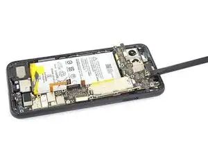
    • Completely remove the motherboard.

    • When removing the motherboard, the small rubber bottom microphone cover may fall off. Don't lose it.

    • When reinstalling the motherboard, check that no ribbon cable connectors are caught underneath.

  39. bccfKalkdjpYlDTc
    bccfKalkdjpYlDTc
    oXiS2HexhBm34GMV
    • Use a pair of tweezers to remove the rear-facing camera module.

Conclusion

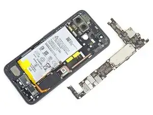
Compare your new replacement part to the original part—you may need to transfer remaining components or remove adhesive backings from the new part before installing.

To reassemble your device, follow the above steps in reverse order.

Take your e-waste to an R2 or e-Stewards certified recycler.

Repair didn’t go as planned? Try some basic troubleshooting, or ask our Answers community for help.

Carsten Frauenheim

Member since: 10/03/20

110978 Reputation

0 comments