Introduction
This is a prerequisite-only guide! This guide is part of another procedure and is not meant to be used alone.
-
-
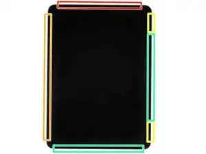
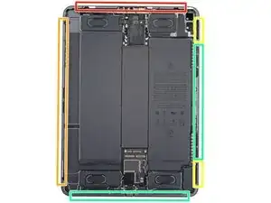
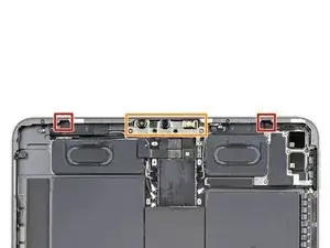
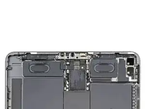
Camera module, ambient light sensors, proximity senor, and front microphone
-
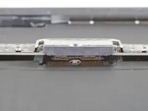
Display cables
-
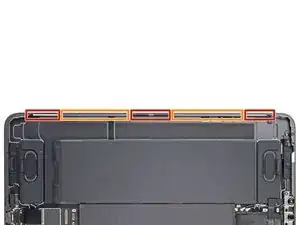
Screen magnets
-
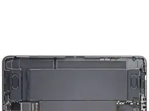
LCD edges
-
-
-
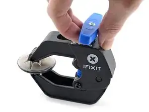
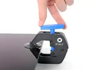
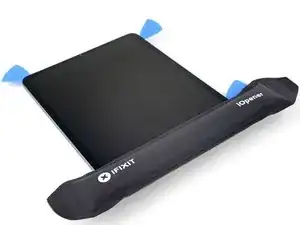
Pull the blue handle backward to unlock the Anti-Clamp's arms.
-
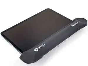
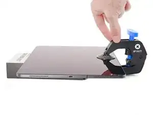
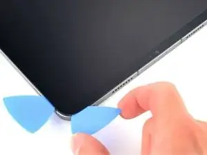
Place an object under your iPad so it rests level between the suction cups.
-
Position the suction cups near the middle of the right edge—one on the top, and one on the bottom.
-
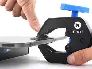
Hold the bottom of the Anti-Clamp steady and firmly press down on the top cup to apply suction.
-
-
-
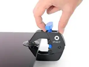
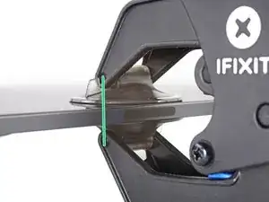
Pull the blue handle forward to lock the arms.
-
Turn the handle clockwise 360 degrees or until the cups start to stretch.
-
Make sure the suction cups remain aligned with each other. If they begin to slip out of alignment, loosen the suction cups slightly and realign the arms.
-
-
-
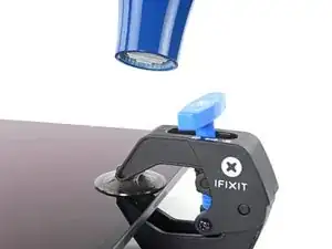
Wait one minute to give the adhesive a chance to release and present an opening gap.
-
If your screen isn't getting hot enough, you can use a hair dryer to heat along the right edge of the iPad.
-
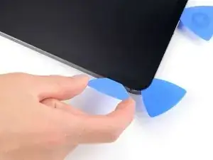
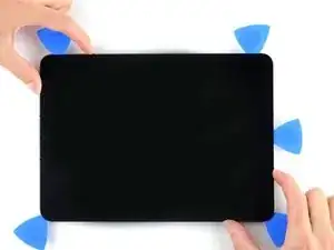
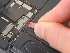
Insert an opening pick under the screen when the Anti-Clamp creates a large enough gap.
-
Skip the next step.
-
-
-
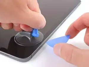
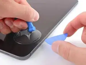
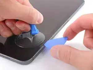
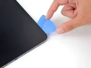
Apply a suction handle to the right edge of the display, about 5 cm from the bottom edge.
-
Pull up on the suction handle with firm, constant pressure to create a gap just small enough to insert an opening pick.
-
Insert the tip of an opening pick into the gap.
-
-
-
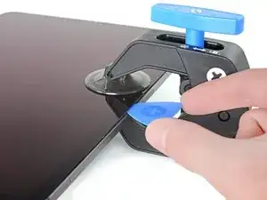
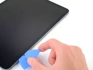
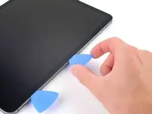
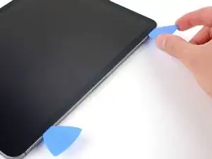
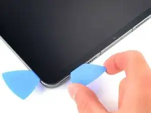
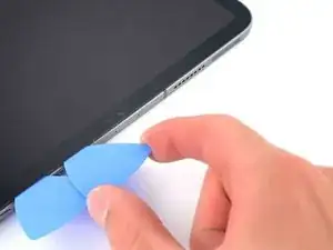
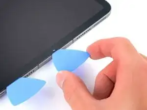
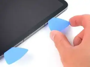
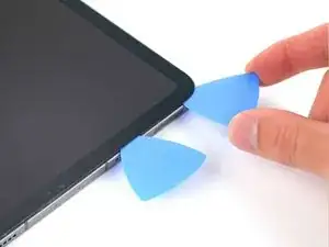
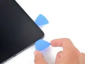
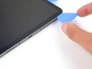
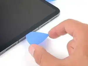
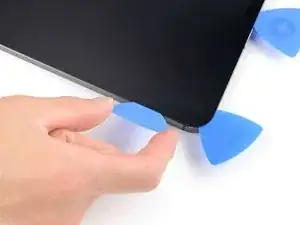
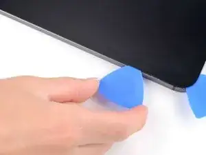
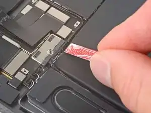
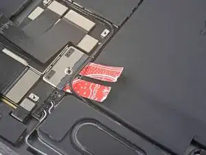
Insert a new opening pick in the gap you just created.
-
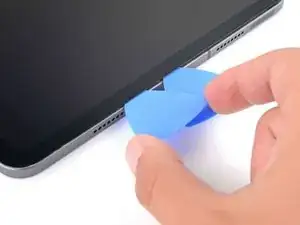
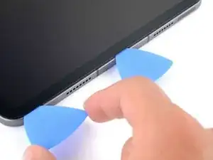
Slide the pick along the right edge to separate the adhesive.
-
Leave the pick in the top right corner to prevent the adhesive from re-sealing.
-
-
-
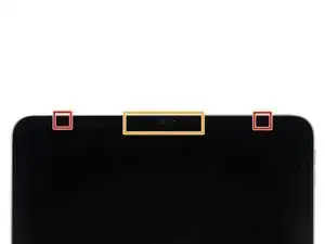
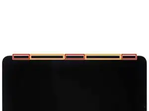
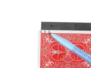
Don't insert an opening pick more than 2 mm near the top left and right edges or you'll damage the ambient light sensors.
-
Don't insert an opening pick more than 1 mm near the middle of the top edge or you'll damage the camera module, proximity sensor, and front microphone.
-
-
-
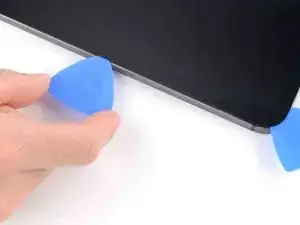
Insert a new opening pick in the gap you just created.
-
Slide the pick along the top right edge, stopping when you reach the right ambient light sensor.
-
Leave the pick to the right of the sensor to prevent the adhesive from re-sealing.
-
-
-
Insert a new opening pick to the right of the ambient light sensor.
-
Slide the pick along the middle section of the top, stopping when you reach the left ambient light sensor.
-
Leave the pick in to prevent the adhesive from re-sealing.
-
-
-
Insert a new opening pick to the left of the ambient light sensor.
-
Slide the pick along the top left edge, stopping when you reach the left ambient light sensor.
-
Once the top edge adhesive has been separated, you can remove the two picks near the ambient light sensors.
-
-
-
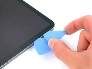
Insert a new opening pick in the bottom right corner below the existing pick.
-
Slide the pick around the bottom right corner to separate the adhesive.
-
-
-
Slide the opening pick along the bottom edge, stopping at the USB-C port.
-
Leave the pick in to prevent the bottom edge adhesive from re-sealing.
-
-
-
Insert a new opening pick to the left of the USB-C port.
-
Separate the remaining bottom edgeadhesive.
-
Leave the pick in the bottom left corner to prevent the bottom edge adhesive from re-sealing.
-
-
-
The display cables are located within small indents of the frame and require an opening pick to be inserted at a 45° angle.
-
There are flat sections of the frame which require an opening pick to be inserted horizontally.
-
-
-
Insert an opening pick at a 45˚ angle just above the bottom left corner.
-
Carefully slide the pick along the left edge, stopping when you reach the flat section of the frame.
-
-
-
Lower the opening pick so it is horizontal to the display.
-
Continue separating the left edge adhesive until you reach the next indented section of the frame.
-
-
-
Separate the remaining adhesive, making sure to follow the instructions exactly as written.
-
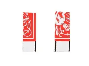
Slide the pick at a 45˚ downward angle and don't insert the pick more than 5 mm.
-
Slide the pick horizontally and don't insert the pick more than 5 mm.
-
-
-
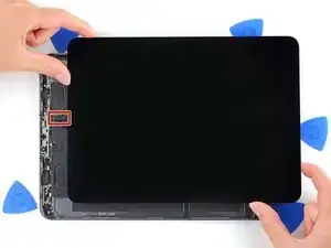
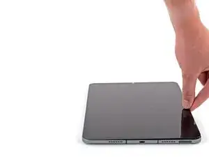
Grab two opposing corners of the screen and gently separate the rest of the adhesive.
-
Shift the screen towards the bottom right corner of the frame until the ambient light sensor ribbon cable near the top edge is uncovered.
-
-
-
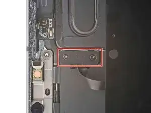
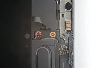
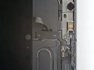
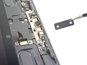
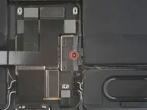
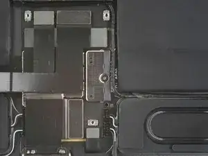
Use a Phillips screwdriver to remove the two screws securing the ambient light sensor cable bracket to the logic board:
-
One 1.3 mm screw
-
One 2.0 mm screw
-
-
-
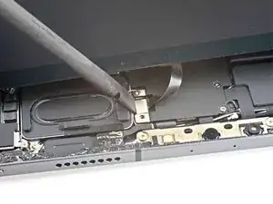
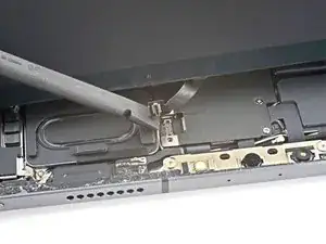
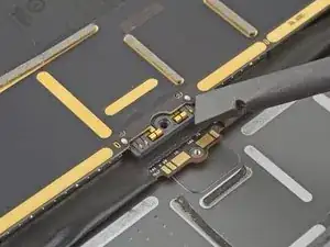
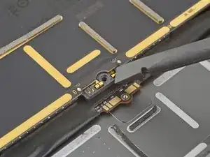
Use the flat end of a spudger to disconnect the ambient light sensor cable by lifting straight up on the press connectors.
-
-
-
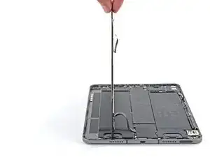
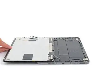
Grip the right edge of the screen and fold it open like a book.
-
Lay the screen down over the left edge of the iPad.
-
-
-
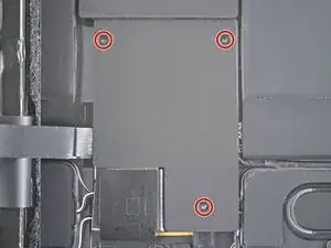
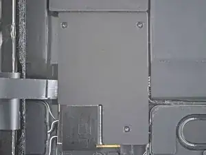
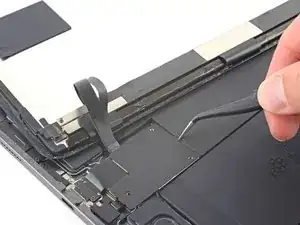
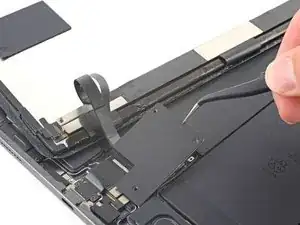
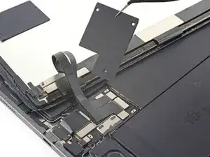
Use a Phillips screwdriver to remove the three 1.2 mm screws securing the lower cable shield to the logic board.
-
-
-
Use a Phillips screwdriver to remove the 1.8 mm screw securing the battery connector to the logic board.
-


To reassemble your device, follow these instructions in reverse order.