Introduction
Use this guide to replace the right RGB thumbstick ring in your Asus ROG Ally.
If your right thumbstick ring doesn't light up, or lights up intermittently, it may be time to replace the thumbstick ring.
-
-
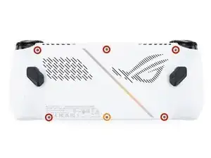
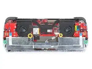
Use a Phillips #0 screwdriver to remove the five 17.2 mm‑long screws securing the top edge and bottom corners of the back cover.
-
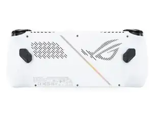
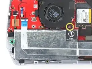
Use a Phillips #0 screwdriver to fully loosen the remaining captive screw at the center of the bottom edge. This should create a small gap between the back cover and chassis.
-
-
-
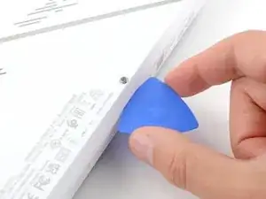
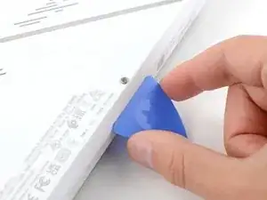
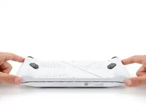
Insert the flat edge of an opening pick between the bottom edge of the back cover and chassis, near the captive screw.
-
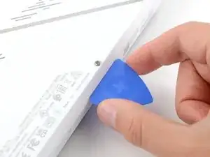
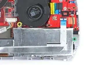
Angle the pick upward and push it under the back cover.
-
-
-
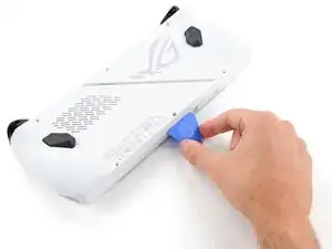
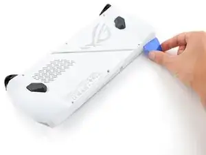
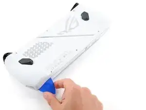
Slide the opening pick along the bottom edge and around the corners of the back cover to release the clips securing it.
-
-
-
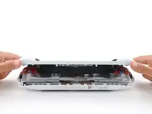
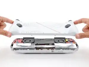
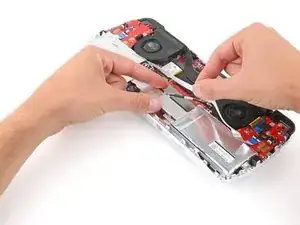
Lift the bottom edge of the back cover off the chassis to release the remaining clips.
-
Remove the back cover.
-
-
-
Use the flat end of a spudger to gently push the locking bar away from the connector to unlatch it.
-
-
-
Insert the flat end of a spudger under the center of the battery connector.
-
Lift the connector straight up and out of its socket to disconnect the battery.
-
-
-
Use a Phillips #00 screwdriver to remove the four screws securing the battery:
-
Two 9.6 mm‑long screws near the center of the top edge
-
Two 3.4 mm‑long screws at the left and right edges
-
-
-
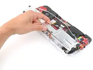
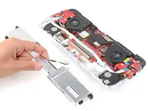
With one hand, hold the ribbon cable that runs along the top of the battery out of the way.
-
With your free hand, lift the battery straight up and remove it.
-
-
-
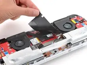
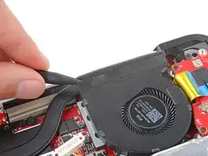
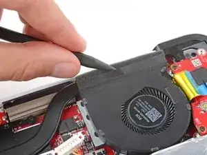
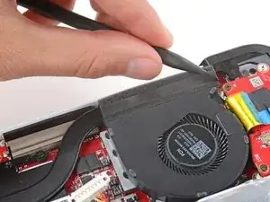
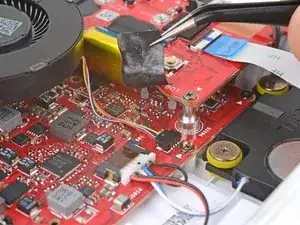
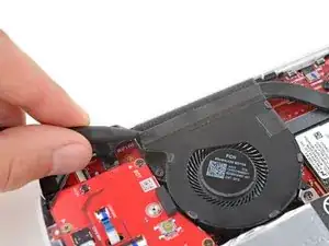
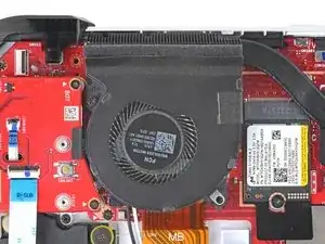
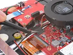
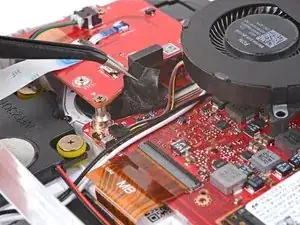
Insert the point of a spudger between the tape on the upper edge of the fan and the heatsink foam.
-
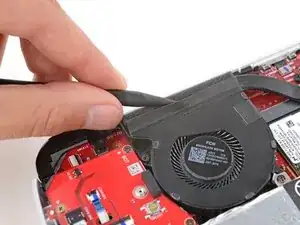
Slide the spudger under the length of the tape to separate it from the foam.
-
-
-
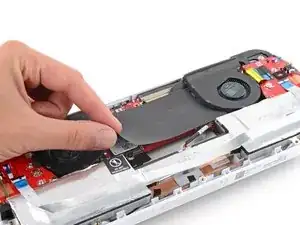
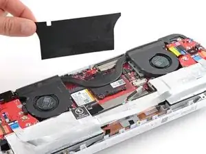
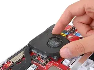
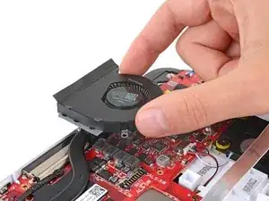
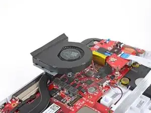
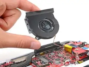
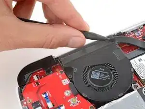
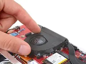
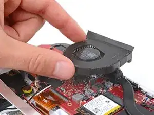
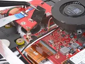
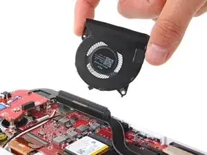
Gently lift the fan and set it on top of the heatsink foam so you can access the fan cables.
-
-
-
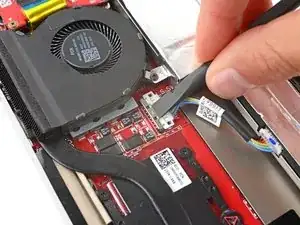
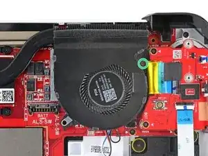
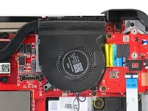
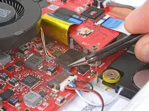
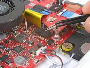
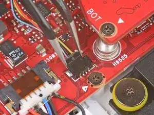
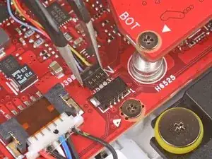
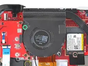
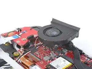
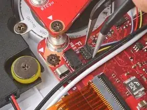
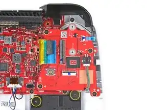
Use tweezers to peel up and remove the piece of tape securing the fan cables to the motherboard.
-
-
-
Insert the point of a spudger between the tape on the upper edge of the fan and the heatsink foam.
-
Slide the spudger under the length of the tape to separate it from the foam.
-
-
-
Gently lift the fan and set it on top of the heatsink foam so you can access the fan cables.
-
-
-
Use tweezers to peel up and remove the piece of tape securing the fan cables to the motherboard.
-
-
-
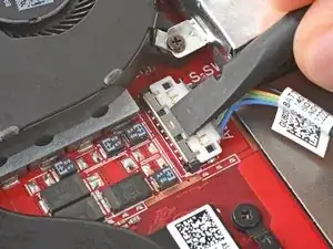
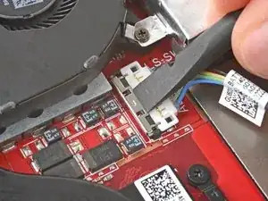
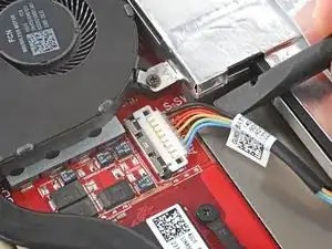
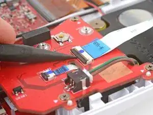
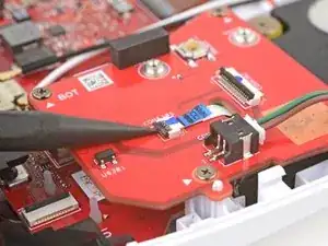
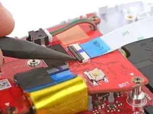
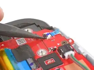
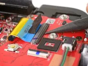
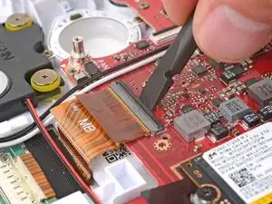
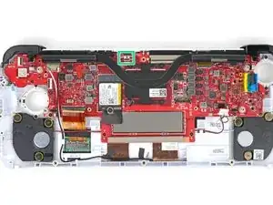
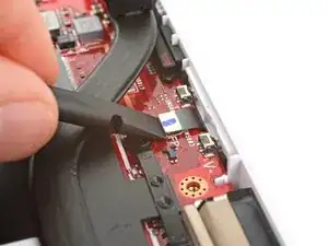
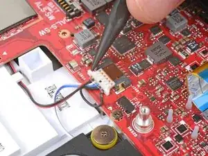
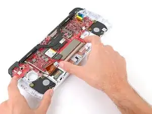
Use a spudger or a clean fingernail to lift the locking flap on the thumbstick interconnect cable ZIF connector, located on the right thumbstick board.
-
Use tweezers to grip the cable's blue pull tab and pull the connector straight out of its socket.
-
-
-
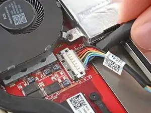
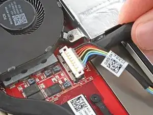
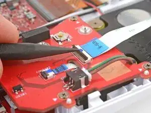
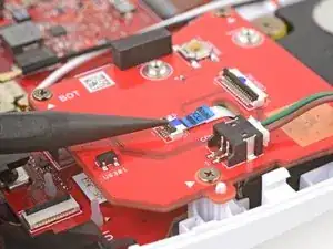
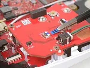
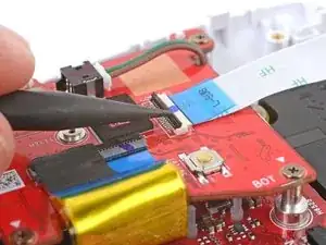
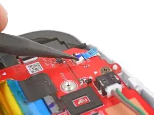
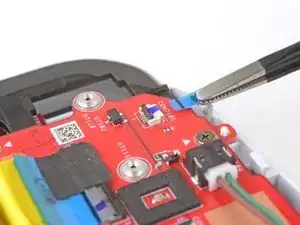
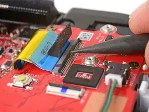
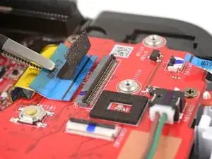
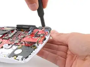
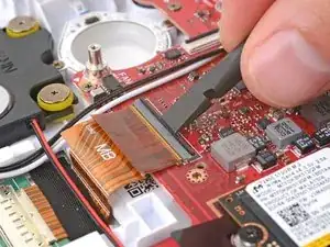
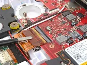
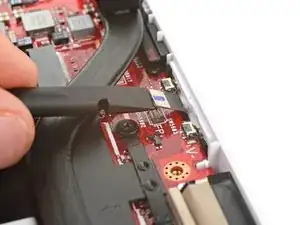
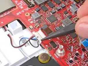
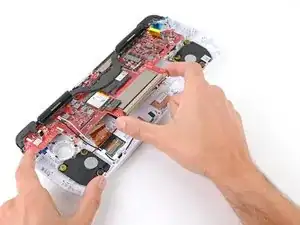
Use the point of a spudger to lift the locking flap on the right thumbstick ring ZIF connector.
-
Use tweezers to grip the cable's blue pull tab and pull the connector straight out of its socket.
-
-
-
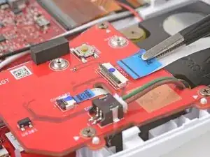
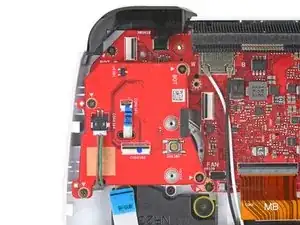
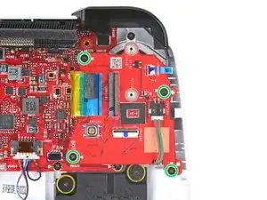
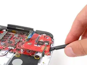
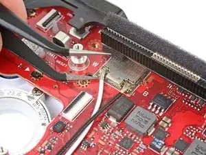
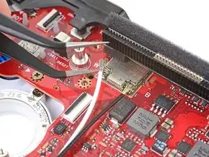
Use a Phillips #00 screwdriver to remove the four 3.4 mm‑long screws securing the right thumbstick assembly.
-
-
-
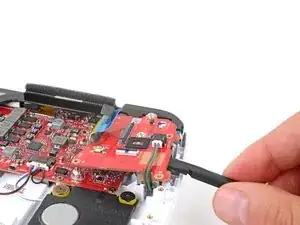
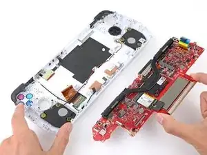
Insert the flat end of a spudger between the bottom left edge of the thumbstick assembly and the chassis.
-
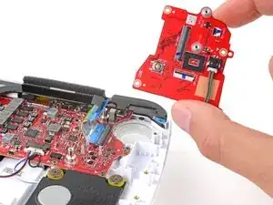
Pry up the thumbstick assembly and remove it, making sure to thread the thumbstick ring cable through its cutout.
-
Orient the board over your device thumbstick side down.
-
Thread the thumbstick ring cable through its cutout on the board.
-
Lift the left edge of your device and push the thumbstick assembly firmly into place so the small circular cutouts on the left edge go over their alignment posts. The board should stay firmly in place.
-
-
-
Use a spudger or a clean fingernail to lift the locking flap on the thumbstick interconnect cable ZIF connector, located on the left thumbstick board.
-
Use tweezers to grip the cable's blue pull tab and pull the connector straight out of its socket.
-
-
-
Use the point of a spudger to lift the locking flap on the left thumbstick ring ZIF connector.
-
Use tweezers to grip the cable's blue pull tab and pull the connector straight out of its socket.
-
-
-
Use a spudger or a clean fingernail to lift the locking flap on the main board interconnect cable ZIF connector.
-
Use tweezers to grip the cable's blue pull tab and pull the connector straight out of its socket.
-
-
-
Use a Phillips #00 screwdriver to remove the four 3.4 mm‑long screws securing the left thumbstick assembly.
-
-
-
Insert the flat end of a spudger between the bottom right edge of the thumbstick assembly and the chassis.
-
Pry up the thumbstick assembly and remove it.
-
Orient the board over your device thumbstick side down.
-
Thread the thumbstick ring cable through its cutout on the board.
-
Lift the right edge of your device and push the thumbstick assembly firmly into place so the small circular cutouts on the right edge go over their alignment posts. The board should stay firmly in place.
-
-
-
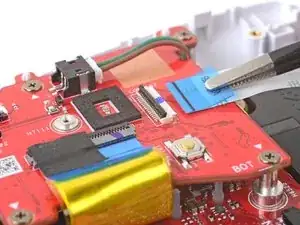
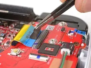
Use the flat end of a spudger or a clean fingernail to lift the locking flap on the screen cable ZIF connector, located on the bottom left corner of the motherboard.
-
Use tweezers to grip the cable's orange pull tab and pull the connector straight out of its socket.
-
-
-
Use the flat end of a spudger to pry up and disconnect the power button press connector from the middle of the motherboard's top edge.
-
-
-
Use the point of a spudger to push on alternating sides of the speakers sliding connector at the bottom right edge of the motherboard to "walk" it out of its socket.
-
-
-
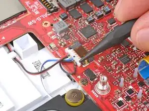
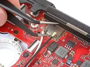
Slide one arm of your angled tweezers under the metal neck of one of the antenna cables coaxial connectors, near the top left corner of the motherboard.
-
Gently lift straight up to disconnect the cable.
-
Repeat the disconnection process for the other antenna cable.
-
-
-
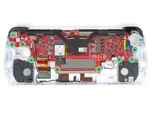
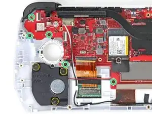
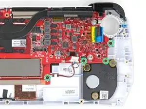
Use a Phillips #00 screwdriver to remove the nine 3.4 mm‑long screws securing the motherboard.
-
-
-
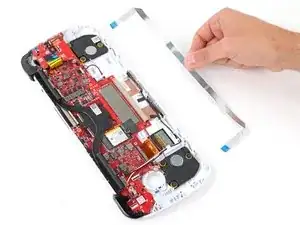
With one hand, firmly secure your device.
-
With your free hand, lift the bottom edge of the motherboard and pull it towards the bottom of the chassis to remove it.
-
With one hand, lift the top edge of your device so the actions buttons and D-Pad aren't touching your work surface.
-
Visually check that all the buttons are fully and properly in their recesses. If they aren't, they won't press correctly.
-
With your device lifted, use your free hand to slide the motherboard into place at a slight downward angle.
-
-
-
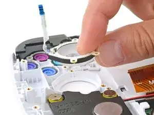
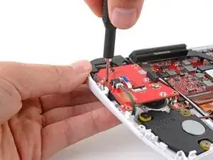
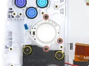
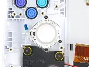
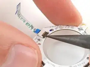
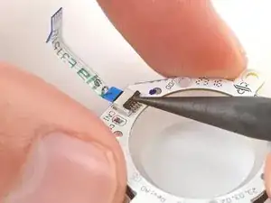
Use a Phillips #00 screwdriver to remove the three 3.4 mm‑long screws securing the right RGB thumbstick ring.
-
-
-
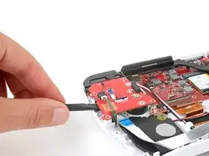
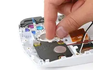
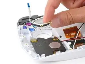
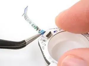
With one hand, firmly secure the thumbstick ring.
-
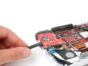
With your free hand, use the point of a spudger to flip up the locking flap on the thumbstick ring ZIF connector.
-
-
-
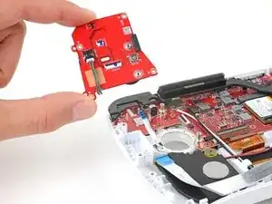
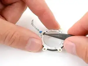
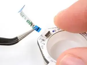
Use tweezers or your fingers to gently pull the cable straight out of its socket and remove it.
-


To reassemble your device, follow these instructions in reverse order.
Take your e-waste to an R2 or e-Stewards certified recycler.
Repair didn’t go as planned? Try some basic troubleshooting, or ask our Answers community for help.