Introduction
Use this guide to replace, change, or upgrade the buttons in your Analogue Pocket.
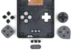
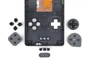
This guide shows how to replace three sets of buttons:
- Action buttons (historically A, B, X, and Y)
- Home and menu buttons
- D-pad and components
-
-
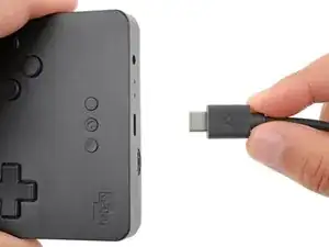
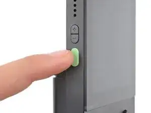
Unplug all cables and fully power off your device.
-
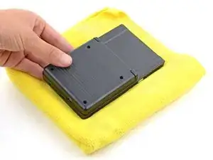
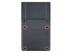
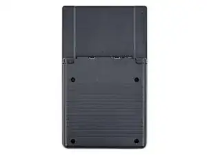
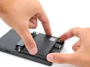
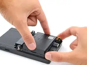
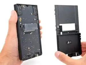
Working on your device requires laying it screen-side down. To prevent damage, lay it on a soft surface such as a towel.
-
-
-
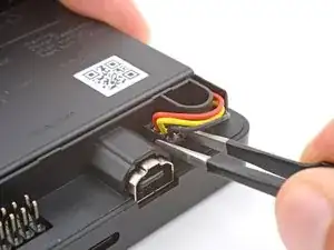
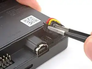
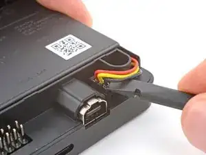
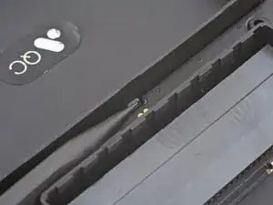
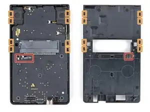
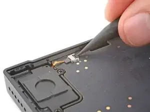
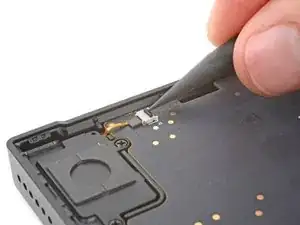
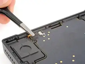
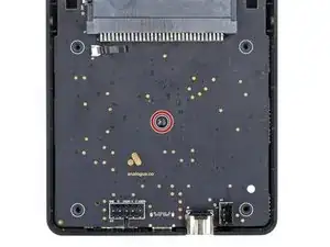
Use blunt nose tweezers to pull the battery connector out of its socket on the bottom right corner of your device.
-
-
-
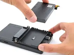
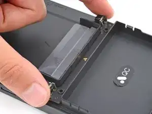
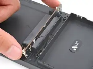
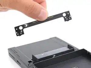
Swing the bottom edge of the button board up and over the cartridge reader.
-
Set the board on top of the cartridge reader so the cable's connector is facing the bottom of the device.
-
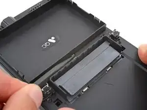
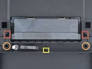
Put the top edges of the board under their tabs on the rear shell.
-
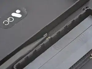
Lay the board onto the rear shell so the alignment posts go into their circular cutouts on the board.
-
Press the board down until the plastic clip engages.
-
-
-
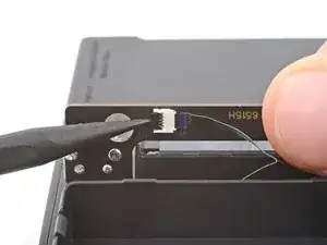
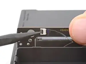
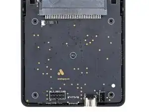
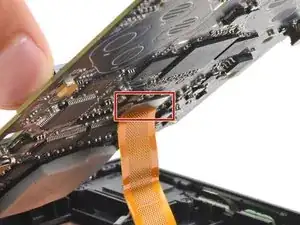
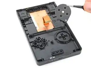
Use the tip of a spudger or a clean fingernail to flip up the hinged locking flap on the board cable ZIF connector located on the board itself.
-
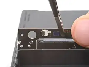
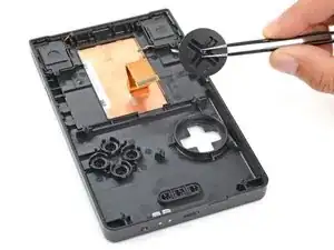
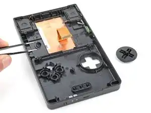
Use blunt nose tweezers to pull the cable straight out of its socket.
-
-
-
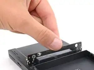
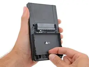
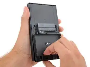
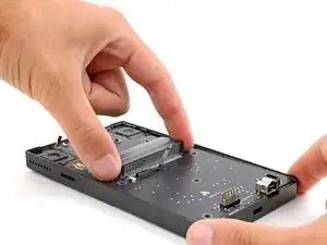
Firmly grip your device with one hand.
-
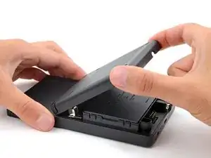
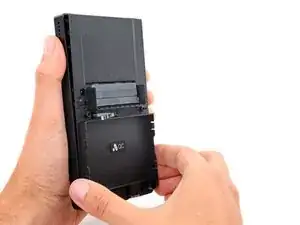
With your free hand, lift the bottom edge of the rear shell until it clears the front shell.
-
Pull the rear shell down until the sliding tabs disengage.
-
-
-
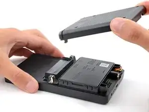
Remove the rear shell.
-
Thread the button board cable through its slot in the rear shell.
-
Lay the rear shell on the front shell so its bottom edge slightly overhangs.
-
Push the rear shell in and slide it up to engage the sliding tabs.
-
-
-
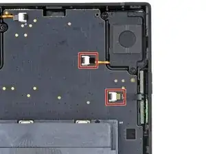
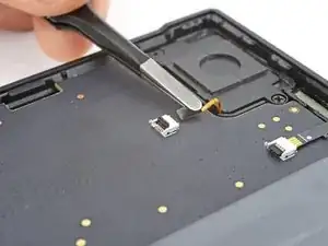
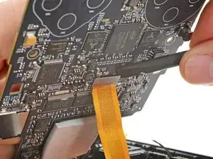
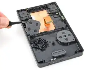
Use the tip of a spudger or a clean fingernail to flip up the hinged locking flap on the right speaker cable ZIF connector.
-
Use blunt nose tweezers to pull the cable straight out of its socket.
-
-
-
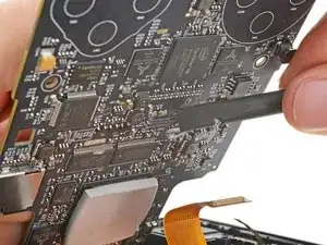
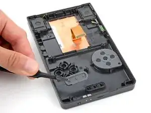
Repeat the process to disconnect the left speaker and power/volume button cables from their ZIF connectors.
-
-
-
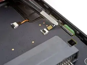
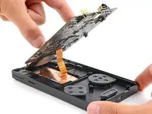
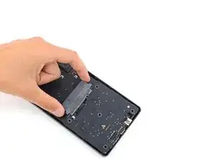
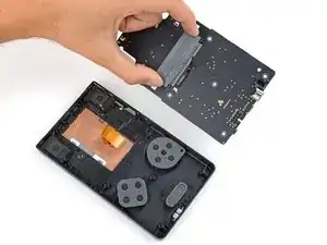
Grip the outer edges of the cartridge reader and gently lift the bottom edge of the main board until you can access the screen cable.
-
Keep the main board raised for the next step.
-
-
-
Insert the flat end of a spudger under the top right corner of the screen cable press connector.
-
Twist the spudger to disconnect the screen cable.
-
-
-
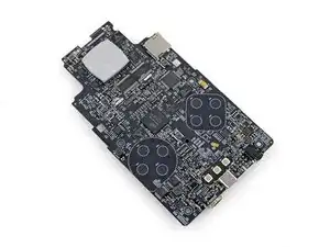
Lift and remove the main board from the front shell.
-
To prevent damaging any surface mounted components, lay the board on your workspace cartridge reader side down.
-


To reassemble your device, follow these instructions in reverse order.
Take your e-waste to an R2 or e-Stewards certified recycler.
Repair didn’t go as planned? Try some basic troubleshooting, or ask our Answers community for help.