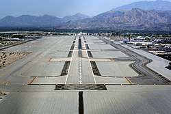
Runway
According to the International Civil Aviation Organization (ICAO), a runway is a "defined rectangular area on a land aerodrome prepared for the landing and takeoff of aircraft". Runways may be a man-made surface (often asphalt, concrete, or a mixture of both) or a natural surface (grass, dirt, gravel, ice, sand or salt). Runways, as well as taxiways and ramps, are sometimes referred to as "tarmac", though very few runways are built using tarmac. Runways made of water for seaplanes are generally referred to waterways. Runway lengths are now commonly given in meters worldwide, except in North America where feet are commonly used.[1]
%2C_Netherlands_PP1151411211.jpg)
History
In 1916, in a World War I war effort context, the first concrete-paved runway was built in Clermont-Ferrand in France, allowing local company Michelin to manufacture Bréguet Aviation military aircraft.
In January 1919, aviation pioneer Orville Wright underlined the need for "distinctly marked and carefully prepared landing places, [but] the preparing of the surface of reasonably flat ground [is] an expensive undertaking [and] there would also be a continuous expense for the upkeep."[2]
Runway headings
For fixed-wing aircraft, it is advantageous to perform takeoffs and landings into the wind to reduce takeoff or landing roll and reduce the ground speed needed to attain flying speed. Larger airports usually have several runways in different directions, so that one can be selected that is most nearly aligned with the wind. Airports with one runway are often constructed to be aligned with the prevailing wind. Compiling a wind rose is in fact one of the preliminary steps taken in constructing airport runways.[3] Note that wind direction is given as the direction the wind is coming from: a plane taking off from runway 09 faces east, into an "east wind" blowing from 090°.
Originally in the 1920s and 1930s, airports and air bases (particularly in the United Kingdom) were built in a triangle-like pattern of three runways at 60° angles to each other. The reason was that back then aviation was only starting, and as a result although it was known that winds affect runway distance required, etc. not much was known about wind behaviour. As a result, three runways in a triangle-like pattern were built, and the runway with the heaviest traffic on it would eventually expand into an airport's main runway, while the other two runways would be either abandoned or converted into taxiways.[4] For example Bristol Airport has only one runway - 09/27 (9/27) - and two taxiways that form a 'V' which may have been runways on the original 1930s RAF Lulsgate Bottom airbase.
Naming

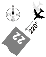
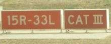
Runways are named by a number between 01 and 36, which is generally the magnetic azimuth of the runway's heading in decadegrees. This heading differs from true north by the local magnetic declination. A runway numbered 09 points east (90°), runway 18 is south (180°), runway 27 points west (270°) and runway 36 points to the north (360° rather than 0°).[5] When taking off from or landing on runway 09, a plane is heading around 90° (east). A runway can normally be used in both directions, and is named for each direction separately: e.g., "runway 15" in one direction is "runway 33" when used in the other. The two numbers differ by 18 (= 180°). For clarity in radio communications, each digit in the runway name is pronounced individually: runway one-five, runway three-three, etc. (instead of "fifteen" or "thirty-three").
A leading zero, for example in "runway zero-six" or "runway zero-one-left", is included for all ICAO and some U.S. military airports (such as Edwards Air Force Base). However, most U.S. civil aviation airports drop the leading zero as required by FAA regulation.[6] This also includes some military airfields such as Cairns Army Airfield. This American anomaly may lead to inconsistencies in conversations between American pilots and controllers in other countries. It is very common in a country such as Canada for a controller to clear an incoming American aircraft to, for example, runway 04, and the pilot read back the clearance as runway 4. In flight simulation programs those of American origin might apply U.S. usage to airports around the world. For example, runway 05 at Halifax will appear on the program as the single digit 5 rather than 05.
Military airbases may include smaller paved runways known as "assault strips" for practice and training next to larger primary runways.[7] These strips eschew the standard numerical naming convention and instead employ the runway's full three digit heading; examples include Dobbins Air Reserve Base's Runway 110/290 and Duke Field's Runway 180/360.[8][9]
Runways with non-hard surfaces, such as small turf airfields and waterways at seaplanes, may use the standard numerical scheme or may use traditional compass point naming, examples include Ketchikan Harbor Seaplane Base's Waterway E/W.[10][11] Airports with unpredictable or chaotic water currents, such as Santa Catalina Island's Pebbly Beach Seaplane Base, may designate their landing area as Waterway ALL/WAY to denote the lack of designated landing direction.[12][11]
Letter suffix
If there is more than one runway pointing in the same direction (parallel runways), each runway is identified by appending left (L), center (C) and right (R) to the number to identify its position (when facing its direction)—for example, runways one-five-left (15L), one-five-center (15C), and one-five-right (15R). Runway zero-three-left (03L) becomes runway two-one-right (21R) when used in the opposite direction (derived from adding 18 to the original number for the 180° difference when approaching from the opposite direction). In some countries, regulations mandate that where parallel runways are too close to each other, only one may be used at a time under certain conditions (usually adverse weather).
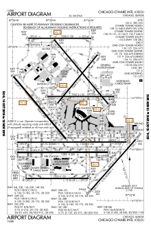
At large airports with four or more parallel runways (for example, at Chicago O'Hare, Los Angeles, Detroit Metropolitan Wayne County, Hartsfield-Jackson Atlanta, Denver, Dallas-Fort Worth and Orlando), some runway identifiers are shifted by 1 to avoid the ambiguity that would result with more than three parallel runways. For example, in Los Angeles, this system results in runways 6L, 6R, 7L, and 7R, even though all four runways are actually parallel at approximately 69°. At Dallas/Fort Worth International Airport, there are five parallel runways, named 17L, 17C, 17R, 18L, and 18R, all oriented at a heading of 175.4°. Occasionally, an airport with only three parallel runways may use different runway identifiers, such as when a third parallel runway was opened at Phoenix Sky Harbor International Airport in 2000 to the south of existing 8R/26L — rather than confusingly becoming the "new" 8R/26L it was instead designated 7R/25L, with the former 8R/26L becoming 7L/25R and 8L/26R becoming 8/26.
Suffixes may also be used to denote special use runways. Airports that have seaplane waterways may chose to denote the waterway on charts with the suffix W; such as Daniel K. Inouye International Airport in Honolulu and Lake Hood Seaplane Base in Anchorage.[13] Small airports that host various forms of air traffic may employ additional suffixes to denote special runway types based on the type of aircraft expected to use them, including STOL (S), glider (G), and ultralight runways (U).[11] Runways that are numbered relative to true north rather than magnetic north will use the suffix T; this is advantageous for certain airfields in the far north such as Thule Air Base.[14]
Renumbering
Runway designations may change over time because Earth's magnetic lines slowly drift on the surface and the magnetic direction changes. Depending on the airport location and how much drift occurs, it may be necessary to change the runway designation. As runways are designated with headings rounded to the nearest 10°, this affects some runways sooner than others. For example, if the magnetic heading of a runway is 233°, it is designated Runway 23. If the magnetic heading changes downwards by 5 degrees to 228°, the runway remains Runway 23. If on the other hand the original magnetic heading was 226° (Runway 23), and the heading decreased by only 2 degrees to 224°, the runway becomes Runway 22. Because magnetic drift itself is slow, runway designation changes are uncommon, and not welcomed, as they require an accompanying change in aeronautical charts and descriptive documents. When a runway designation does change, especially at major airports, it is often done at night, because taxiway signs need to be changed and the huge numbers at each end of the runway need to be repainted to the new runway designators. In July 2009 for example, London Stansted Airport in the United Kingdom changed its runway designations from 05/23 to 04/22 during the night.
Declared distances
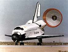
Runway dimensions vary from as small as 245 m (804 ft) long and 8 m (26 ft) wide in smaller general aviation airports, to 5,500 m (18,045 ft) long and 80 m (262 ft) wide at large international airports built to accommodate the largest jets, to the huge 11,917 m × 274 m (39,098 ft × 899 ft) lake bed runway 17/35 at Edwards Air Force Base in California – developed as a landing site for the Space Shuttle.[15]
Takeoff and landing distances available are given using one of the following terms:
- TORA[16][17]
- Takeoff Run Available – The length of runway declared available and suitable for the ground run of an airplane taking off.[18]
- TODA[16][17]
- Takeoff Distance Available – The length of the takeoff run available plus the length of the clearway, if clearway is provided.[18]
- (The clearway length allowed must lie within the aerodrome or airport boundary. According to the Federal Aviation Regulations and Joint Aviation Requirements (JAR) TODA is the lesser of TORA plus clearway or 1.5 times TORA).
- ASDA[16][17]
- Accelerate-Stop Distance Available – The length of the takeoff run available plus the length of the stopway, if stopway is provided.[18]
- LDA[16][17]
- Landing Distance Available – The length of runway that is declared available and suitable for the ground run of an airplane landing.[19]
- EMDA[20]
- Emergency Distance Available – LDA (or TORA) plus a stopway.
Sections of a runway

There exist standards for runway markings.[21]
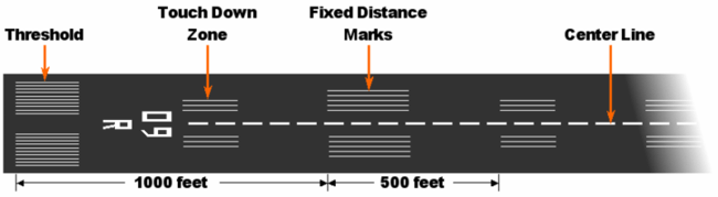
- The runway thresholds are markings across the runway that denote the beginning and end of the designated space for landing and takeoff under non-emergency conditions.[22]
- The runway safety area is the cleared, smoothed and graded area around the paved runway. It is kept free from any obstacles that might impede flight or ground roll of aircraft.
- The runway is the surface from threshold to threshold, which typically features threshold markings, numbers, and centerlines, but not overrun areas at both ends.
- Blast pads, also known as overrun areas or stopways, are often constructed just before the start of a runway where jet blast produced by large planes during the takeoff roll could otherwise erode the ground and eventually damage the runway. Overrun areas are also constructed at the end of runways as emergency space to slowly stop planes that overrun the runway on a landing that has not gone to plan, or to slowly stop a plane on a rejected takeoff or a takeoff that has not gone to plan. Blast pads are often not as strong as the main paved surface of the runway and are marked with yellow chevrons. Regardless of circumstances regarding blast pad use, usage of the blast pad for taxiing, take off or landing, save for an emergency, is not permitted.

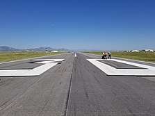
- Displaced thresholds may be used for taxiing, takeoff, and landing rollout, but not for touchdown. A displaced threshold often exists because obstacles just before the runway, runway strength, or noise restrictions may make the beginning section of runway unsuitable for landings.[23] It is marked with white paint arrows that lead up to the beginning of the landing portion of the runway. Like with blast pads, landings on displaced thresholds of the runway are not permitted save for an emergency or any other circumstance that may require displaced threshold use.

Runway markings
There are runway markings and signs on most large runways. Larger runways have a distance remaining sign (black box with white numbers). This sign uses a single number to indicate the remaining distance of the runway in thousands of feet. For example, a 7 will indicate 7,000 ft (2,134 m) remaining. The runway threshold is marked by a line of green lights.
There are three types of runways:
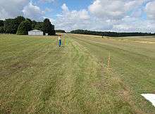
- Visual runways are used at small airstrips and are usually just a strip of grass, gravel, ice, asphalt, or concrete. Although there are usually no markings on a visual runway, they may have threshold markings, designators, and centerlines. Additionally, they do not provide an instrument-based landing procedure; pilots must be able to see the runway to use it. Also, radio communication may not be available and pilots must be self-reliant.
- Non-precision instrument runways are often used at small- to medium-size airports. These runways, depending on the surface, may be marked with threshold markings, designators, centerlines, and sometimes a 1,000 ft (305 m) mark (known as an aiming point, sometimes installed at 1,500 ft (457 m)). While centerlines provide horizontal position guidance, aiming point markers provide vertical position guidance to planes on visual approach.
- Precision instrument runways, which are found at medium- and large-size airports, consist of a blast pad/stopway (optional, for airports handling jets), threshold, designator, centerline, aiming point, and 500 ft (152 m), 1,000 ft (305 m)/1,500 ft (457 m), 2,000 ft (610 m), 2,500 ft (762 m), and 3,000 ft (914 m) touchdown zone marks. Precision runways provide both horizontal and vertical guidance for instrument approaches.
Waterways may be unmarked or marked with buoys that follow maritime notation instead.[24]
National variants
- In Australia, Canada, Japan, the United Kingdom,[25] as well as some other countries or territories (Hong Kong and Macau) all 3-stripe and 2-stripe touchdown zones for precision runways are replaced with one-stripe touchdown zones.
- In some South American countries like Colombia, Ecuador and Peru, one 3-stripe is added and a 2-stripe is replaced with the aiming point.
- Some European countries replace the aiming point with a 3-stripe touchdown zone.
- Runways in Norway have yellow markings instead of the usual white ones. This also occurs in some airports in Japan, Sweden, and Finland. The yellow markings are used to ensure better contrast against snow.
- Runways may have different types on each end. To cut costs, many airports do not install precision guidance equipment on both ends. Runways with one precision end and any other type of end can install the full set of touchdown zones, even if some are past the midpoint. Runways with precision markings on both ends omit touchdown zones within 900 ft (274 m) of the midpoint, to avoid ambiguity over the end with which the zone is associated.
Runway lighting

A line of lights on an airfield or elsewhere to guide aircraft in taking off or coming in to land or an illuminated runway is sometimes also known as a flare path.
Technical specifications


Runway lighting are used at airports for use at night and low visibility. Seen from the air, runway lights form an outline of the runway. A runway may have some or all of the following:[26]
- Runway end identifier lights (REIL) – unidirectional (facing approach direction) or omnidirectional pair of synchronized flashing lights installed at the runway threshold, one on each side.
- Runway end lights – a pair of four lights on each side of the runway on precision instrument runways, these lights extend along the full width of the runway. These lights show green when viewed by approaching aircraft and red when seen from the runway.
- Runway edge lights – white elevated lights that run the length of the runway on either side. On precision instrument runways, the edge-lighting becomes amber in the last 2,000 ft (610 m) of the runway, or last third of the runway, whichever is less. Taxiways are differentiated by being bordered by blue lights, or by having green centre lights, depending on the width of the taxiway, and the complexity of the taxi pattern.
- Runway centerline lighting system (RCLS) – lights embedded into the surface of the runway at 50 ft (15 m) intervals along the runway centerline on some precision instrument runways. White except the last 900 m (3,000 ft): alternate white and red for next 600 m (1,969 ft) and red for last 300 m (984 ft).[26]
- Touchdown zone lights (TDZL[16]) – rows of white light bars (with three in each row) at 30 or 60 m (98 or 197 ft) intervals on either side of the centerline for 900 m (3,000 ft).[26]
- Taxiway centerline lead-off lights – installed along lead-off markings, alternate green and yellow lights embedded into the runway pavement. It starts with green light at about the runway centerline to the position of first centerline light beyond the Hold-Short markings on the taxiway.
- Taxiway centerline lead-on lights – installed the same way as taxiway centerline lead-off Lights, but directing airplane traffic in the opposite direction.
- Land and hold short lights – a row of white pulsating lights installed across the runway to indicate hold short position on some runways that are facilitating land and hold short operations (LAHSO).[26]
- Approach lighting system (ALS) – a lighting system installed on the approach end of an airport runway and consists of a series of lightbars, strobe lights, or a combination of the two that extends outward from the runway end.
According to Transport Canada's regulations,[27] the runway-edge lighting must be visible for at least 2 mi (3 km). Additionally, a new system of advisory lighting, runway status lights, is currently being tested in the United States.[28]
The edge lights must be arranged such that:
- the minimum distance between lines is 75 ft (23 m), and maximum is 200 ft (61 m);
- the maximum distance between lights within each line is 200 ft (61 m);
- the minimum length of parallel lines is 1,400 ft (427 m);
- the minimum number of lights in the line is 8.[29]
| Wikimedia Commons has media related to Runway lights. |
.jpg)
Control of lighting system
Typically the lights are controlled by a control tower, a flight service station or another designated authority. Some airports/airfields (particularly uncontrolled ones) are equipped with pilot-controlled lighting, so that pilots can temporarily turn on the lights when the relevant authority is not available.[30] This avoids the need for automatic systems or staff to turn the lights on at night or in other low visibility situations. This also avoids the cost of having the lighting system on for extended periods. Smaller airports may not have lighted runways or runway markings. Particularly at private airfields for light planes, there may be nothing more than a windsock beside a landing strip.
Runway safety
Types of runway safety incidents include:
- Runway excursion - an incident involving only a single aircraft, where it makes an inappropriate exit from the runway (e.g. Thai Airways Flight 679).
- Runway overrun (also known as an overshoot) - a type of excursion where the aircraft is unable to stop before the end of the runway (e.g. Air France Flight 358, TAM Airlines Flight 3054).
- Runway incursion - an incident involving incorrect presence of a vehicle, person or another aircraft on the runway (e.g. Aeroflot Flight 3352, Scandinavian Airlines Flight 686).
- Runway confusion - an aircraft makes use of the wrong runway for landing or takeoff (e.g. Singapore Airlines Flight 006, Western Airlines Flight 2605).
- Runway undershoot - an aircraft that lands short of the runway (e.g. British Airways Flight 38, Asiana Airlines Flight 214).
Pavement

The choice of material used to construct the runway depends on the use and the local ground conditions. For a major airport, where the ground conditions permit, the most satisfactory type of pavement for long-term minimum maintenance is concrete. Although certain airports have used reinforcement in concrete pavements, this is generally found to be unnecessary, with the exception of expansion joints across the runway where a dowel assembly, which permits relative movement of the concrete slabs, is placed in the concrete. Where it can be anticipated that major settlements of the runway will occur over the years because of unstable ground conditions, it is preferable to install asphaltic concrete surface, as it is easier to patch on a periodic basis. Fields with very low traffic of light planes may use a sod surface. Some runways make use of salt flats.
For pavement designs, borings are taken to determine the subgrade condition, and based on the relative bearing capacity of the subgrade, the specifications are established. For heavy-duty commercial aircraft, the pavement thickness, no matter what the top surface, varies from 10 in (250 mm) to 4 ft (1 m), including subgrade.
Airport pavements have been designed by two methods. The first, Westergaard, is based on the assumption that the pavement is an elastic plate supported on a heavy fluid base with a uniform reaction coefficient known as the K value. Experience has shown that the K values on which the formula was developed are not applicable for newer aircraft with very large footprint pressures.
The second method is called the California bearing ratio and was developed in the late 1940s. It is an extrapolation of the original test results, which are not applicable to modern aircraft pavements or to modern aircraft landing gear. Some designs were made by a mixture of these two design theories. A more recent method is an analytical system based on the introduction of vehicle response as an important design parameter. Essentially it takes into account all factors, including the traffic conditions, service life, materials used in the construction, and, especially important, the dynamic response of the vehicles using the landing area.
Because airport pavement construction is so expensive, manufacturers aim to minimize aircraft stresses on the pavement. Manufacturers of the larger planes design landing gear so that the weight of the plane is supported on larger and more numerous tires. Attention is also paid to the characteristics of the landing gear itself, so that adverse effects on the pavement are minimized. Sometimes it is possible to reinforce a pavement for higher loading by applying an overlay of asphaltic concrete or portland cement concrete that is bonded to the original slab. Post-tensioning concrete has been developed for the runway surface. This permits the use of thinner pavements and should result in longer concrete pavement life. Because of the susceptibility of thinner pavements to frost heave, this process is generally applicable only where there is no appreciable frost action.
Pavement surface
Runway pavement surface is prepared and maintained to maximize friction for wheel braking. To minimize hydroplaning following heavy rain, the pavement surface is usually grooved so that the surface water film flows into the grooves and the peaks between grooves will still be in contact with the aircraft tires. To maintain the macrotexturing built into the runway by the grooves, maintenance crews engage in airfield rubber removal or hydrocleaning in order to meet required FAA friction levels.
Surface type codes
In aviation charts, the surface type is usually abbreviated to a three-letter code.
The most common hard surface types are asphalt and concrete. The most common soft surface types are grass and gravel.
| * ASP | Asphalt |
| * BIT | Bituminous asphalt or tarmac |
| * BRI | Bricks (no longer in use, covered with asphalt or concrete now) |
| * CLA | Clay |
| * COM | Composite |
| * CON | Concrete |
| * COP | Composite |
| * COR | Coral (fine crushed coral reef structures) |
| * GRE | Graded or rolled earth, grass on graded earth |
| * GRS | Grass or earth not graded or rolled |
| * GVL | Gravel |
| * ICE | Ice |
| * LAT | Laterite |
| * MAC | Macadam |
| * PEM | Partially concrete, asphalt or bitumen-bound macadam |
| * PER | Permanent surface, details unknown |
| * PSP | Marston Matting (derived from pierced/perforated steel planking) |
| * SAN | Sand |
| * SMT | Sommerfeld Tracking |
| * SNO | Snow |
| * U | Unknown surface |
| * WAT | Water |
Runway length
A runway of at least 6,000 ft (1,800 m) in length is usually adequate for aircraft weights below approximately 200,000 lb (91,000 kg). Larger aircraft including widebodies will usually require at least 8,000 ft (2,400 m) at sea level and somewhat more at higher altitude airports. International widebody flights, which carry substantial amounts of fuel and are therefore heavier, may also have landing requirements of 10,000 ft (3,000 m) or more and takeoff requirements of 13,000 ft (4,000 m). The Boeing 747 is considered to have the longest takeoff distance of the more common aircraft types and has set the standard for runway lengths of larger international airports.
At sea level, 10,000 ft (3,000 m) can be considered an adequate length to land virtually any aircraft. For example, at O'Hare International Airport, when landing simultaneously on 4L/22R and 10/28 or parallel 9R/27L, it is routine for arrivals from East Asia, which would normally be vectored for 4L/22R (7,500 ft (2,286 m)) or 9R/27L (7,967 ft (2,428 m)) to request 28R (13,000 ft (3,962 m)). It is always accommodated, although occasionally with a delay. Another example is that the Luleå Airport in Sweden was extended to 10,990 ft (3,350 m) to allow any fully loaded freight aircraft to take off.
An aircraft taking off at a higher altitude must do so at reduced weight due to decreased density of air at higher altitudes, which reduces engine power and wing lift. An aircraft must also take off at a reduced weight in hotter or more humid conditions (see density altitude). Most commercial aircraft carry manufacturer's tables showing the adjustments required for a given temperature.
Wind rose diagrams have been proved to be very useful nowadays in the design of airport runway.
In India, recommendations of International Civil Aviation Organization (ICAO) are now followed more often. For landing, only altitude correction is done for runway length whereas for take-off, all types of correction are taken into consideration.[31]
The world's longest paved runway, at Qamdo Bamda Airport in Tibet (China), has a total length of 5,500 m (18,045 ft).
See also
- ICAO recommendations on use of the International System of Units
- Engineered materials arrestor system
- Instrument landing system (ILS)
- List of airports
- Pavement classification number (PCN)
- Precision approach path indicator
- Runway visual range
- Tabletop runway
- Visual approach slope indicator
- Helipad
- Highway strip
References
- Aviation's Crazy, Mixed Up Units of Measure - AeroSavvy
- Rupa Haria (Jan 10, 2018). "1919: Orville Wright On The Future Of Civil Flying". Aviation Week Network.
- Retrieved on 2012-02-24.
- https://aviation.stackexchange.com/questions/61396/when-and-why-was-runway-07-25-at-kai-tak-removed
- Federal Aviation Administration Aeronautical Information Manual, Chapter 2, Section 3 Airport Marking Aids and Signs part 3b Archived 2012-01-18 at the Wayback Machine
- "FAA Advisory Circular AC 150/5340-1L - Standards for Airport Markings; Chapter 2.3.e.(2) [page 17] states "A single-digit runway landing designation number is never preceded by a zero."".
- https://www.amc.af.mil/News/Article-Display/Article/146910/new-assault-landing-strip-opens-in-wyoming-mcchord-c-17-makes-first-landing/
- "Duke Field (Eglin AF Aux Nr 3) Airport". Airnav.com. July 16, 2020. Retrieved August 5, 2020.
- "Dobbins Air Reserve Base". Airnav.com. July 16, 2020. Retrieved August 5, 2020.
- "Ketchikan Harbor Seaplane Base". Airnav.com. July 16, 2020. Retrieved August 8, 2020.
- FAA AC 150/5200-35
- "Pebbly Beach Seaplane Base". Airnav.com. July 16, 2020. Retrieved August 5, 2020.
- "Daniel K Inouye International Airport". Airnav.com. July 16, 2020. Retrieved August 5, 2020.
- Jeppesen Airport Chart Legend
- Edwards AFB Rogers Lakebed Airport Diagram (PDF), effective 13 Aug 2020. Federal Aviation Administration.
- "Order JO 7340.1Z: Contractions" (PDF). Federal Aviation Administration. March 15, 2007.
- ICAO Annex 14, Aerodrome Design and Operations Vol 1. ICAO. 2016. pp. Chapter 1-Definitions, Chapter 2.8-declared distances, Attachment A section 3. ISBN 978-92-9258-031-5.
- Airplanes: Turbine engine powered: Takeoff limitations, retrieved 2009-10-04
- Airplanes: Turbine engine powered: Landing limitations: Destination airports, retrieved 2009-10-04
- Swatton, Peter J. (2000). Aircraft Performance Theory for Pilots (illustrated, reprint ed.). Oxford, United Kingdom: Blackwell Science Ltd. p. vii. ISBN 0632055693.
- FAA AC 150/5340-1L – Standards for Airport Markings pages 13 and following
- (PDF) http://128.173.204.63/courses/cee4674/cee4674_pub/markings_airports_rev.pdf. Retrieved 2013-07-10. Missing or empty
|title=(help) - Pilot's Handbook of Aeronautical Knowledge FAA-H-8083-25A, p. 306
- FAA-H-8083-23, Seaplane, Skiplane, and Float/Ski Equipped Helicopter Operations Handbook (Chapters 1–3)
- CAP637, Visual aids handbook, chapter 2, page 3, Issue 2, May 2007, Civil Aviation Authority
- "Aerodrome Design and Operations" (PDF) (3 ed.). July 1999. Archived from the original (PDF) on 2012-07-23.
- "§7.8 Runway Lighting". TP 14371: Transport Canada Aeronautical Information Manual. Archived from the original on 2013-03-22.
- FAA Installs Runway Safety Warning System at LAX, archived from the original on 2011-06-06, retrieved 2010-05-14
- Transport Canada Aeronautical Information Manual Archived 2008-06-17 at the Wayback Machine
- "§7.18 Aircraft Radio Control of Aerodrome Lighting". TP 14371: Transport Canada Aeronautical Information Manual. Archived from the original on 2013-03-22.
- "Runway Incursion and Airport Design - SKYbrary Aviation Safety". www.skybrary.aero. Retrieved 2020-01-01.
External links
| Look up runway in Wiktionary, the free dictionary. |
| Wikimedia Commons has media related to Runway. |
- United States Aeronautical Information Manual – Federal Aviation Administration (published yearly)
- United States Airport/Facility Directory (d-AFD) – Federal Aviation Administration (published every 56 days)
- United States Terminal Procedures Publication/Airport Diagrams (d-TPP) – Federal Aviation Administration (published every 28 days)
- North American Powered Parachute Federation
- Visual Aids Handbook – Civil Aviation Authority