Virtually imaged phased array
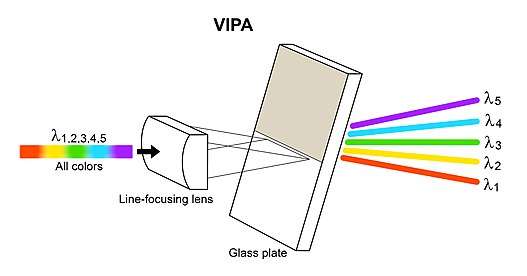
A virtually imaged phased array (VIPA) is an angular dispersive device that, like a prism or a diffraction grating, splits light into its spectral components. It works almost independently of polarization. In contrast to prisms or regular diffraction gratings, it has a much higher angular dispersion but has a smaller free spectral range. This aspect is similar to that of an Echelle grating which is usually used in reflection, since high diffraction orders are also used there. The VIPA can be a compact optical component with high wavelength resolving power.
Basic mechanism
In a virtually imaged phased array, the phased array is the optical analogue of a phased array antenna at radio frequencies. Unlike a diffraction grating which can be interpreted as a real phased array, in a virtually imaged phased array the phased array is created in a virtual image. More specifically, the optical phased array is virtually formed with multiple virtual images of a light source. This is the fundamental difference from an Echelle grating, where a similar phased array is formed in the real space. The virtual images of a light source in the VIPA are automatically aligned exactly at a constant interval, which is critical for optical interference. This is an advantage of the VIPA over an Echelle grating. When the output light is observed, the virtually imaged phased array works as if light were emitted from a real phased array.
History and applications
VIPA was proposed and named by Shirasaki in 1996.[1] The details of this new approach to producing angular dispersion were described in the patent.[2] The VIPA was initially of particular interest in the field of optical communications technology. The VIPA was first applied to optical wavelength division multiplexing (WDM) and a wavelength demultiplexer was demonstrated for a channel spacing of 0.8 nm,[1] which was a standard channel spacing then. Later, a much smaller channel separation of 24 pm and a 3 dB bandwidth of 6 pm were achieved by Weiner at 1550 nm wavelength range.[3] For another application, by utilizing the wavelength-dependent length of the light path due to the angular dispersion of the VIPA, the compensation of chromatic dispersion of fibers was studied and demonstrated.[4][5] The compensation was further developed for tunable systems by using adjustable mirrors[6][7][8] or a spatial light modulator (SLM).[9] Using the VIPA, compensation of polarization mode dispersion was also achieved.[10] Furthermore, pulse shaping using the combination of a VIPA for high-resolution wavelength splitting/recombining and a SLM was demonstrated.[11]
A drawback of the VIPA is its limited free spectral range due to the high diffraction order. To expand the functional wavelength range, a VIPA can be combined with a regular diffraction grating.[12] Similarly to a common configuration with an Echelle grating, the combination of a VIPA and a regular diffraction grating provides a broadband two-dimensional spectral disperser. This was demonstrated for high-resolution WDM (> 1000 channels),[13] but has also been applied to the field of spectroscopy.[14] In microscopy, an endoscope was demonstrated using the two-dimensional spectral disperser.[15] The VIPA has recently been used for an astrophysical instrument [16] and Brillouin spectroscopy in biomechanics.[17]
Structure and operational principle
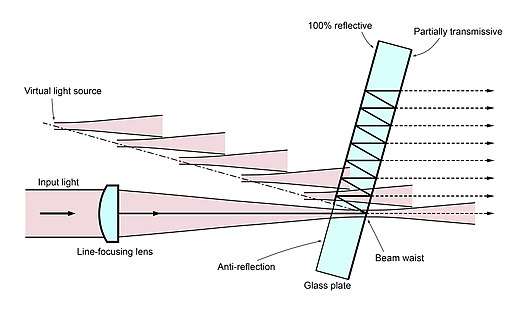
The main component of a VIPA is a glass plate whose normal is slightly tilted with respect to the input light. One side (light input side) of the glass plate is coated with a 100% reflective mirror and the other side (light output side) is coated with a highly reflective but partially transmissive mirror. The side with the 100% reflective mirror has an anti-reflection coated light entrance area, through which a light beam enters the glass plate. The input light is line-focused at the partially transmissive mirror on the light output side. A typical line-focusing lens is a cylindrical lens, which is also part of the VIPA. The light beam is diverging after the beam waist located at the line-focused position.
After the light enters the glass plate through the light entrance area, the light is reflected at the partially transmissive mirror and the 100% reflective mirror, and thus the light travels back and forth between the partially transmissive mirror and the 100% reflective mirror.
When the light beam is reflected each time at the partially transmissive mirror, a small portion of the light power passes through the mirror and travels away from the glass plate. For a light beam passing through the mirror after multiple reflections, the position of the line-focus can be seen in the virtual image when observed from the light output side. Therefore, this light beam travels as if it originated at a virtual light source located at the position of the line-focus and diverged from the virtual light source. The positions of the virtual light sources for all the transmitted light beams automatically align along the normal to the glass plate with a constant spacing, that is, a number of virtual light sources are superimposed to create an optical phased array. Due to the interference of all the light beams, the phased array emits a collimated light beam in one direction, which is at a wavelength dependent angle, and therefore, an angular dispersion is produced.
Wavelength resolution
Similarly to the resolving power of a diffraction grating, which is determined by the number of the illuminated grating elements and the order of diffraction, the resolving power of a VIPA is determined by the reflectivity of the back surface of the VIPA and the thickness of the glass plate. For a fixed thickness, a high reflectivity causes light to stay longer in the VIPA. This creates more virtual sources of light and thus increases the resolving power. On the other hand, with a lower reflectivity, the light in the VIPA is quickly lost, meaning fewer virtual sources of light are superimposed. This results in lower resolving power.
For large angular dispersion with high resolving power, the dimensions of the VIPA should be accurately controlled. Fine tuning of the VIPA characteristics was demonstrated by developing an elastomer-based structure.[18]
A constant reflectivity of the partially transmissive mirror in the VIPA produces a Lorentzian power distribution when the output light is imaged onto a screen, which has a negative effect on the wavelength selectivity. This can be improved by providing the partially transmissive mirror with a linearly decreasing reflectivity. This leads to a Gaussian-like power distribution on a screen and improves the wavelength selectivity or the resolving power.[19]
Spectral dispersion law
An analytical calculation of the VIPA was first performed by Vega in 2003 [20] based on the theory of plane waves and an improved model based on the Fresnel diffraction theory was developed by Xiao in 2004.[21]
Commercialization of the VIPA
VIPA devices have been commercialized by LightMachinery and Manx Precision Optics as spectral disperser devices or components with various customized design parameters.
References
- Shirasaki, M. (1996). "Large angular dispersion by a virtually imaged phased array and its application to a wavelength demultiplexer". Optics Letters. 21 (5): 366–8. Bibcode:1996OptL...21..366S. doi:10.1364/OL.21.000366. PMID 19865407.
- US patent 5,999,320, Shirasaki, M., "Virtually imaged phased array as a wavelength demultiplexer"
- Xiao, S.; Weiner, A. M. (2005). "An eight-channel hyperfine wavelength demultiplexer using a virtually imaged phased-array (VIPA)". IEEE Photonics Technology Letters. 17 (2): 372. Bibcode:2005IPTL...17..372X. doi:10.1109/LPT.2004.839017.
- Shirasaki, M. (1997). "Chromatic-dispersion compensator using virtually imaged phased array". IEEE Photonics Technology Letters. 9 (12): 1598–1600. Bibcode:1997IPTL....9.1598S. doi:10.1109/68.643280.
- Shirasaki, M.; Cao, S. (March 2001). Compensation of chromatic dispersion and dispersion slope using a virtually imaged phased array. 2001 Optical Fiber Communication Conference. Anaheim, CA. Paper TuS1.
- Shirasaki, M.; Kawahata, Y.; Cao, S.; Ooi, H.; Mitamura, N.; Isono, H.; Ishikawa, G.; Barbarossa, G.; Yang, C.; Lin, C. (September 2000). Variable dispersion compensator using the virtually imaged phased array (VIPA) for 40-Gbit/s WDM transmission systems. 2000 European Conference on Optical Communication. Munich, Germany. Paper PD-2.3.
- Garrett, L. D.; Gnauck, A. H.; Eiselt, M. H.; Tkach, R. W.; Yang, C.; Mao, C.; Cao, S. (March 2000). Demonstration of virtually-imaged phased-array device for tunable dispersion compensation in 16 X10 Gb/s WDM transmission over 480 km standard fiber. 2000 Optical Fiber Communication Conference. Baltimore, MD. Paper PD7.
- Cao, S.; Lin, C.; Barbarossa, G.; Yang, C. (July 2001). Dynamically tunable dispersion slope compensation using a virtually imaged phased array (VIPA). 2001 LEOS Summer Topical Meetings Tech. Dig. Copper Mountain, CO.
- Lee, G-H; Xiao, S.; Weiner, A. M. (2006). "Optical dispersion compensator with >4000-ps/nm tuning range using a virtually imaged phased array (VIPA) and spatial light modulator (SLM)". IEEE Photonics Technology Letters. 18 (17): 1819. Bibcode:2006IPTL...18.1819L. doi:10.1109/LPT.2006.880732.
- Miao, H.; Weiner, A. M.; Mirkin, L.; Miller, P. J. (2008). "AII-order polarization-mode dispersion (PMD) compensation via virtually imaged phased array (VIPA) - based pulse shaper". IEEE Photonics Technology Letters. 20 (8): 545. Bibcode:2008IPTL...20..545M. doi:10.1109/LPT.2008.918893.
- Supradeepa, V. R.; Hamidi, E.; Leaird, D. E.; Weiner, A. M. (2010). "New aspects of temporal dispersion in high resolution Fourier pulse shaping: A quantitative description with virtually imaged phased array pulse shapers". Journal of the Optical Society of America B. 27 (9): 1833. arXiv:1004.4693. Bibcode:2010JOSAB..27.1833S. doi:10.1364/JOSAB.27.001833.
- US patent 5,973,838, Shirasaki, M., "Apparatus which includes a virtually imaged phased array (VIPA) in combination with a wavelength splitter to demultiplex wavelength division multiplexed (WDM) light"
- Xiao, S.; Weiner, A. W. (2004). "2-D wavelength demultiplexer with potential for >1000 channels in the C-band". Optics Express. 12 (13): 2895–902. Bibcode:2004OExpr..12.2895X. doi:10.1364/OPEX.12.002895. PMID 19483805.
- Nugent-Glandorf, L.; Neely, T.; Adler, F.; Fleisher, A. J.; Cossel, K. C.; Bjork, B.; Dinneen, T.; Ye, J.; Diddams, S. A. (2012). "Mid-infrared virtually imaged phased array spectrometer for rapid and broadband trace gas detection". Optics Letters. 37 (15): 3285–7. arXiv:1206.1316. Bibcode:2012OptL...37.3285N. doi:10.1364/OL.37.003285. PMID 22859160.
- Tsia, K. K.; Goda, K.; Capewell, D.; Jalali, B. (2009). "Simultaneous mechanical-scan-free confocal microscopy and laser microsurgery". Optics Letters. 34 (14): 2099–101. Bibcode:2009OptL...34.2099T. doi:10.1364/OL.34.002099. hdl:10722/91309. PMID 19823514.
- Bourdarot, G.; Coarer, E. L.; Bonfils, X.; Alecian, E.; Rabou, P.; Magnard, Y. (2017). "NanoVipa: a miniaturized high-resolution echelle spectrometer, for the monitoring of young stars from a 6U Cubesat". CEAS Space Journal. 9 (4): 411. Bibcode:2017CEAS....9..411B. doi:10.1007/s12567-017-0168-2.
- Antonacci, G.; de Turris, V.; Rosa, A.; Ruocco, G. (2018). "Background-deflection Brillouin microscopy reveals altered biomechanics of intracellular stress granules by ALS protein FUS". Communications Biology. 10 (139): 139. doi:10.1038/s42003-018-0148-x. PMC 6131551. PMID 30272018.
- Metz, P.; Block, H.; Behnke, C.; Krantz, M.; Gerken, M.; Adam, J. (2013). "Tunable elastomer-based virtually imaged phased array". Optics Express. 21 (3): 3324–35. Bibcode:2013OExpr..21.3324M. doi:10.1364/OE.21.003324. PMID 23481792.
- Shirasaki, M.; Akhter, A. N.; Lin, C. (1999). "Virtually imaged phased array with graded reflectivity". IEEE Photonics Technology Letters. 11 (11): 1443. Bibcode:1999IPTL...11.1443S. doi:10.1109/68.803073.
- Vega, A.; Weiner, A. M.; Lin, C. (2003). "Generalized grating equation for virtually-imaged phased-array spectral dispersers". Applied Optics. 42 (20): 4152–5. Bibcode:2003ApOpt..42.4152V. doi:10.1364/AO.42.004152. PMID 12856727.
- Xiao, S.; Weiner, A. M.; Lin, C. (2004). "A dispersion law for virtually imaged phased-array spectral dispersers based on paraxial wave theory". IEEE Journal of Quantum Electronics. 40 (4): 420. Bibcode:2004IJQE...40..420X. doi:10.1109/JQE.2004.825210.