TRAME
TRAME (TRAnsmission of MEssages)[1] was the name of the second computer network in the world similar to Internet to be used in an electric utility. Like Internet, the base technology was packet switching and it was developed by the electric utility ENHER in Barcelona and deployed by this same Utility first in Catalonia and Aragón, Spain, and later in other places. Its development started in year 1974 and the first routers, called nodes by that time, were deployed by year 1978.[2][3][4][5] The network has been in operation until year 2016 (38 years), obviously with successive technological software and hardware updates.
Beginnings
In year 1974, packet switching was a technology known only in research circles. The concept started by year 1968 associated to the USA's Advanced Research Projects Agency (ARPA) research project ARPAnet. The idea of applying the packet switching concept to electric utilities control communication networks first appeared in 1974 when the Swedish Power Utility Vattenfall started to create its TIDAS packet switching network [6][7][8] and it was followed by the Spanish electric utility ENHER,[9] which was targeting to telecontrol and automate its high voltage power network. With that goal ENHER created a specific team of people for developing both the packet switching network and the supervisory control and data acquisition (SCADA) system also named telecontrol system. In year 1978 the first four TRAME[1] routers were already available [2] and in year 1980 eight of them were already deployed and operating.[1][5][10] The printed circuit boards (PCBs) controlling the communication lines were connected to a shared memory PCB allowing them to exchange data and messages. The project was developed together with its main initial application, the Telecontrol or SCADA system SICL (Sistema Integral de Control Local) [11][12][13] with which initially they shared a very similar hardware. By year 1980 the maximum link capacity was 9.600 bit/s which in 1980 was the maximum possible on a voice channel of 4 kHz width. These channels were the basic unit of the then analog communication systems in use. By that time power utilities used either telephone calls or low speed (below 1200bit/s) dedicated links for telecontrol, typically shared among ten high voltage electrical substations.
Services
The basic service provided by the TRAME[1] network was SCADA or Telecontrol to automate the high voltage power network, thus improving operational efficiency, until then operated manually with telephone communication among human operators. Each TRAME router had associated one or several remote terminal units (RTUs) of the SICL telecontrol system.[11][12] It also connected screens, and later PCs, located in substations to interchange messages among them and with the Control Center [13] located in the known Casa Fuster in of Barcelona. It was a kind of predecessor of the today's e-mail now so popular. Later, in the 1990s, other protocols (X.25, IP) were developed to include corporate information technology (IT) terminals, company physical surveillance systems and other services. Besides, applications and terminals for the transmission of voice and video over the TRAME network were developed [14][15]
Protocols
The TRAME's routing system,[3] like in the original ARPAnet, was based on the Bellman-Ford algorithm but with "split-horizon" [7] as in the Swedish TIDAS network but with an original improvement.[3] This protocol allows to find optimal paths in meshed networks for each packet to transmit allowing the sharing of the same network by multiple services. Opposedly, the traditional technology of circuit switching, established dedicated circuits for each service or communication. The addressing of routers and terminals used an own system with an address of 16bits; It would be the equivalent to the well-known IP (Internet Protocol) version 4 (IPv4), still in use in today’s Internet which uses addresses of 32 bits. It is necessary to bear in mind that by year 1978 the IPv4 protocol did not exist yet since the IPv4 version used in Internet did not appear until year 1981, and in fact, did not reach the large public until much later.
The line protocols were also proprietary and were named UCL, the one linking routers between them, and UTR, the access one. They were designed to offer the higher quality of service required by telecontrol/SCADA in terms of data integrity and availability set by International Electrotechnical Commission (IEC) standard IEC-870-5-1 and ANSI C37.1. and because the protocol used by then in corporate IT networks, the HDLC, did not offer enough quality for critical industrial applications.[16][17] Later on, other protocols like X.25 and IP were also supported over the TRAME mentioned protocols. In year 2000, the UTR protocol was substituted [18] by the IEC standard IEC 60870- 5-101/104.
Initially network flow control was based in managing 8 data priorities in head-of-the-line (HOL) waiting queues. Later and after some experimentation,[19] a flow control method based on a bit indicating congestion and the management of the gap between packets when accessing the network was adopted. This needed the measurement of the capacity of the path bottleneck.[20][21][22][17][23] Also an end-to-end protocol was added for some flows requiring order preservation like X.25.
Evolution
To survive for 38 years the technology had to support and intense evolution. Basically there had been four TRAME generations which are summarized in the Table.
| Concept | TRAME 1 | TRAME 2 | TRAME 3 | TRAME + |
|---|---|---|---|---|
| Initiation of the development | 1974 | 1993 | 1998 | |
| Initiation of the deployment | 1978 (4 routers in operation) | 1988
1990 (fully deployed) |
1995 | 1999 |
| Processor | Zilog Z80 | Intel 80286 | Intel 80386 | i960CA
i960RM |
| Maximum link speed | 9600bit/s | 64kbit/s | 2Mbit/s | 10Mbit/s |
| Hardware | 16 processors sharing a common memory | 16 processors sharing a common memory | 16 processors sharing a common memory distributed among the 16 PCBs. | A single processor with a shared multimaster 1Gbit/s bus to communicate I/O boards. |
| Hardware developer/manufacturer | ENHER/ISEL (INI) | ENHER/ISEL (INI) | DIMAT, S.A. | DIMAT, S.A. |
| Addressing field | 14 bits · 256 routers(8 bits) · 64 terminals per router(6bits) | 16 bits · 256 routers(8 bits) · 64 terminals per router(6bits) · 4 interconnected networks (2 bits) | 16 bits, as in TRAME 2 | 16 bits, as in TRAME 2 |
| Managed priorities | 8 | 8 | 8 | 8 |
| Inner link protocols | UCL (Proprietary) | UCL improved for 64kbit/s (Proprietary) | UCL improved for 64kbit/s (Proprietary) | UCL improved for 2Mbit/s (Proprietary) |
| Access link protocols | UTR (Proprietary) | · IPv4(1999) · X.25
· Proprietary: UTR |
· International Electrotechnical Commission's IEC 60870-5-101/104 | The same as for TRAME 3 |
| Network size evolution | 1978-4 routers
1980-8 routers 1983-27 routers 1987-32routers |
1994-50 routers | 2004-222 routers
2014-some 3000 routers (several networks) | |
| Aspect of a router | 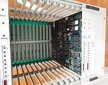 TRAME 1 Router | 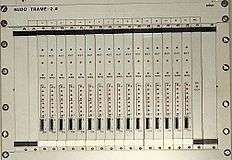 TRAME 2 Router | 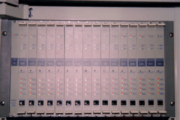 TRAME 3 Router |
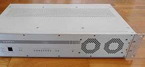 TRAME + Router |
Next a short written description of the four TRAME generations is given.
TRAME 1
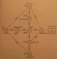
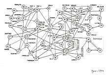
The project was initiated in year 1974 and in year 1978 a first network with 4 routers was already installed and in operation at the electric utility ENHER. In year 1980 the network had already 8 nodes in operation (See Figure I). The hardware was based on the processor Zilog Z80 and had a multiprocessor structure with 16 processors sharing a common memory. The software was developed at ENHER[9] headquarters located in the known Casa Fuster, Passeig de Gràcia, 132, Barcelona, by using the Z80 assembler language. Beyond 1980 the software began to be written in C language and an emulator HP64000 Logic Development System was used was used for the purpose. The hardware was produced by ISEL, an INI company.
The routing system was a variant of Bellman-Ford with split-horizon.[7] It was an improvement of the original ARPA network routing system consisting in an original updating procedure which allows to react faster to changes. The distance function was the number of packets in the output waiting queues plus one.
The line protocols (UCL for the inner lines linking routers and UTR for accessing the network) were designed to cope with the stringent requirements set for telecontrol (SCADA) of high voltage power networks (Standards IEC-870-5-1 and ANSI C37.1).
At the OSI transport layer, windows with a width from 1 to 8, depending on the required service, residing in the terminals were used.
The addresses were of just 14 bits length to address both, the routers (called nodes by then) and the devices connected to them. They were formed by two fields, an 8-bit field to address the router and a sub-address of 6 bit to address the terminals connected to it. The node address was assigned to nodes and not to the ends of the links as in Internet.
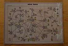
The basic advantages of TRAME[1] with respect to other technologies used in electric utilities by that time were in part due to the packet technology itself: Capacity to manage any network topology, automatic adaptability to topological and traffic changes, integration of different link technologies (digital or analog) and capacities in a single network, open and decentralized intercomunicability among users and devices, simultaneous communication with several users and locations from a single physical connection and integrated network supervision; In fact, the network was provided from its inception with a supervision center [24] formed by a computer and a synoptic board located in the company headquarters (See Figure II).
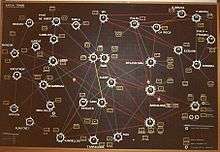
But other advantages were due to the TRAME specific design: high data integrity,[16][17] support for packet priorities, easyness to include special protocols such the many SCADA ones in use by that time. The above resulted in a better quality of the service, specially regarding data availability and data integrity, and in an integration of services in a single network. Part of the evolution of its deployment can be seen in Figures II to IV.
A video introducing TRAME 1 can be found in the following link: https://www.youtube.com/watch?v=Mb4285XKnz0
TRAME 2
In year 1990, TRAME 2 was completely deployed and TRAME 1 substituted. The processor of the new hardware was Intel 80286 and the hardware structure and the external aspect of routers was very similar to that of TRAME 1. The software was written in C language and the mentioned emulator continue to be used.
The improvements over TRAME 1 were the introduction of the standardized X.25 access protocol to enable the connection of corporate IT terminals to the network, the ability to cope with the 64kbit/s of the new digital lines, an increased switching capacity and the introduction of an end-to-end protocol to avoid loss of packets and disordering as required by X.25.
An important improvement was the possibility to use dual homing to increase terminal availability; They could be connected to the network by two access ponints. For the purpose, the terminals had two addresses, a primary one and a secondary one.
Regarding addressing, in 1991 two bits were added to the addressing to indicate the network. The address space was thus increased to 16 bits and up to 4 networks could be freely meshed as in a single one. This addressing scheme was maintained in the following TRAME versions.
TRAME 3
The hardware was again a multiprocessor structure with 16 processors sharing a common memory but this latter one was not a separate PCB but, rather than this, it was distributed among the 16 PCBs to avoid single points of failure. The interconnection of PCBs was a shared multimaster bus of 40Mbit/s capacity as designed and manufactured by the company DIMAT, S.A.. It also included a series channel for maintenance, monitoring, reprogramming and reinitialization of the different modules by a terminal connected to them. The software was developed by ENHER in collaboration with the company DIMAT, S.A.. The routing algorithm continue to be the same but the distance function was changed to a less dynamic one. A flow control procedure based on metering the congestion and backwards indication to the source was introduced.[21][23]
The improvements with respect to TRAME2 were the support of IPv4, the introduction of an SNMP supervision agent, a new Flow Control system, an improved distance metric making the system less dynamic, and an autoexec task to periodically check hardware and software.
TRAME+
The hardware design was radically changed moving to an architecture with a single processor per node as opposed to the traditional TRAME hardware. It had two alternative base modules of different capacity based on processors Intel i960CA and i960RM with a 1Gbit/s bus to communicate the different router PCBs. The number of physical interfaces was just 10 (8 serial + 2 Ethernet (10B2 or 10BT)) because the Ethernet allowed to connect several devices in a single LAN. It also had a frontal service serial channel. By losing redundancy (a single processor per router) the node lost some availability with respect to TRAME previous versions. This was done due to economical reasons coming from the fact that the network was being extended to smaller substations where the cost constraints are more stringent. Dual homing could help in places with more stringent availability requirements.
The improvements with respect to TRAME 3 were the capability to deal with links of 2Mbit/s capacity, smaller and less expensive routers, access by Ethernet and standard protocols; the switch from the UTR proprietary protocol to the ones internationally standardized for SCADA systems ( IEC 60870-5-101 and IEC 60870-5-104) with an original adaptation to packet switching networks.[18][25]
References
- Selga, J.M. « TRAME: A Packet Switching Computer Network for Power Systems». Proceedings of CIGRE (Conference Internationale del Grandes Reseaux Electríques), Paris Session 1978, Paper 35-03, September 1978.
- Hoffmann M.G. and Selga J.M. «Line Control Unit for a Packet Switching Network». Proceedings of MIMI. Zurich, June 1978.
- Selga J.M. and Xampeny J. «Flow-Adaptive Updating Procedure for Dynamic Routing. Comparative Simulation Results». Proceedings of IEEE International Conference on Communications (ICC'80), pages. 23.6.1 to 23.6.6., Seattle (WA), USA, 1980.
- Selga J., Rivera J., Xampeny J. «Modelos analíticos y de simulación utilizados para el diseño de la red de conmutación de mensajes de ENHER». I Symposium Nacional sobre Modelado y Simulación en la Indústría y Servicios Públicos. Sevilla., 7–9 May 1980.
- Selga, J.M., Rivera.J., Xampeny, J. «Red TRAME de conmutación de paquetes». Revista Novática, Vol. VII, num.37, 1981.
- Jerlhagen, T. and B. Leander, B. , “A Message Switching Network Designed for Data Communication and Remote Control”, Proceedings of CIGRE, Paris France, Paper 35-01, August 1974.
- Cegrell, T. «[A Routing Procedure for the TIDAS Message-Switching Network]». IEEE Transactions on Communications, Volume 23, Issue 6, pag. 575-585, June 1975
- Kaijser, Arne (2010). "The Use of Computers for Controlling Electricity Flows in Sweden 1950-1980" in "History of Nordic Computing 3: Third IFIP WG9.7 Conference, HiNC3". Stockholm, Sweden: Springer. pp. 28–33. ISBN 978-3-642-23315-9.
- Sánchez i Vilanova, Llorenç. L’aventura hidroelèctrica de la Ribagorçana-ENHER i la seva influència en la transformació sòcio-econòmica de l’Alta Ribagorça”, Història i Cultura de l’Alta Ribagorça-Volum I (in catalan). La Pobla de Segur: Printer: Casa Torres S.A., Dipòsit legal: L-679-1991, Edits: Associació d’Amics de l’Alta Ribagorça., 1991. ISBN 84-604-0570-2.
- Selga, J.M., Rivera, J.,Xampeny, J. (Book coordinated by A. Alabau and J. Riera) (In Spanish. Red TRAME de conmutación de paquetes (Teleinformática y redes de computadores). Barcelona: Marcombo, p. 95 to 101, First Edition: 1982. Second Edition: 1984, ISBN 84-267-0427- 1.
- Ventosa, J.; Sanchez, M. ; Casals, A.; Rivera, J.; Xampeny, J. «An Integrated Station Local Control-Telecontrol System in the Scenario of an Overall Telecontrol System». IEEE Power Engineering Review, Volume PER-6, Issue:10, pages. 39 - 40, 1986
- Ventosa, J.; Sanchez, M. ; Casals, A.; Rivera, J.; Xampeny, J. «An Integrated Station Local Control-Telecontrol System, in the Scenario of an Overall Telecontrol System]». IEEE Transactions on Power Delivery, Volume: 1, Issue: 4, pages. 159-165, 1986
- Equipo TAC de ENHER «Sistema de Telecontrol integral para redes eléctricas. Una avanzada realización española». In Spanish. Mundo Electrónico. num.110., 1981.
- F. Álvarez-Cuevas Figueroa, M. Bertran, Oller, F., J. M. Selga, «Voice Synchronization in Packet Switching Networks». IEEE Network Magazine, Volume 7; Issue: 5, p. 20-25, September 1993
- J. Dalmau and J.M.Selga «Slow-Video Network». CIGRE SC35 Colloquium in Madrid, September 1995.
- Selga, J.M. and Rivera «HDLC reliability and the FRBS method to improve it». IEEE Seventh Data Communications Symposium Mexico, 1981.
- Selga, Josep Maria «Contribucions al disseny i optimització de xarxes d’ordinadors» (Contributions to the design and optimization of computer networks). In Catalan. Doctoral Thesis, September 1985.
- Cabezas,R.;Selga,J.M.;Samitier,C. «Experience in the implementation of a Telecontrol network based on the IP technology». Proceedings of CIGRE (Conference Internationale des Grandes Reseaux Electriques) Paris Session, Paper 35-201, September 2000.
- Selga J., Xampeny J. «Congestion Control Method for the TRAME network. Description and Simulation Results». IEEE Proceedings of the Mediterranean Electrotechnical Conference MELECON'83. Athens(Greece), 23–25 May 1983.
- Selga, J.M. «Optimum Control of Packet Switching Networks». Electronic Letters. Vol.19., pag. 794-795,15 September 1983.
- Selga, J.M. «Flow Control Method for Packet Networks». Proceedings of the 8th International Conference on Computer Communications ICCC 1986. München, p. 625-630,15-19 September 1986.
- Selga, J.M., Altemir, S. «Uso de redes de conmutación de paquetes en telecontrol» (In Spanish). Proceedings de les Primeres Jornades sobre Telecontrol Industrial. Escola Universitària d'Enginyeria Tècnica Industrial de Barcelona, 3–5 April 1984.
- Selga, J.M. «Optimización del uso de redes de conmutación de paquetes» (In Spanish). VI Congreso de Informática y Automática. Madrid., 15–18 October 1985.
- Selga J.M., Rivera J., Urquizu M., Sirvent J.C. «Centro de supervisión de una red de computadores: aplicación a la red TRAME de ENHER» (In Spanish). Mundo Electrónico. Num 130, June 1983.
- Cabezas,R.;Selga,J.M.;Samitier,C. «A new generation of packet switch designed for the Integration of operational services». CIGRE Colloquium in Krakow, Poland, 13 October 1999.