Strain wave gearing
Strain wave gearing also known as harmonic gearing is a type of mechanical gear system that can improve certain characteristics compared to traditional gearing systems such as helical gears or planetary gears. Harmonic Drive is the brand name of strain wave gear trademarked by the Harmonic Drive company.
It was invented in 1957 by C.W. Musser while he was a research advisor at United Shoe Machinery (USM) and is commonly implemented in robotics,[1] and used in aerospace as well,[2] for gear reduction but may also be used to increase rotational speed, or for differential gearing.
History
The basic concept of strain wave gearing (SWG) was introduced by C.W. Musser in his 1957 patent[3] while he was an advisor at United Shoe Machinery Corp (USM). It was first used successfully in 1960 by USM Co. and later by Hasegawa Gear Works, Ltd. under license of USM. Later, Hasegawa Gear Works, Ltd. became Harmonic Drive Systems Inc. located in Japan and USM Co. Harmonic Drive division became Harmonic Drive Technologies Inc.[4][5]
Mechanics

- input shaft
- wave generator
- flexspline
- circular spline
- output shaft
- housing
Red (middle flexible circle): flex spline (attached to output shaft, which is not shown)
Green (inner oval): wave generator (attached to input shaft; inner ball bearing and shaft are not shown)
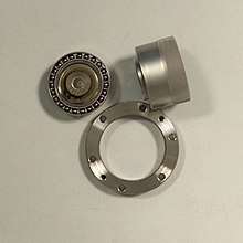
The strain wave gearing theory is based on elastic dynamics and utilizes the flexibility of metal. The mechanism has three basic components: a wave generator (2 / green), a flex spline (3 / red), and a circular spline (4 / blue). More complex versions have a fourth component normally used to shorten the overall length or to increase the gear reduction within a smaller diameter, but still follow the same basic principles.
The wave generator is made up of two separate parts: an elliptical disk called a wave generator plug and an outer ball bearing. The elliptical plug is inserted into the bearing, forcing the bearing to conform to the elliptical shape but still allowing rotation of the plug within the outer bearing.
The flex spline is shaped like a shallow cup. The sides of the spline are very thin, but the bottom is relatively rigid. This results in significant flexibility of the walls at the open end due to the thin wall, and in the closed side being quite rigid and able to be tightly secured (to a shaft, for example). Teeth are positioned radially around the outside of the flex spline. The flex spline fits tightly over the wave generator, so that when the wave generator plug is rotated, the flex spline deforms to the shape of a rotating ellipse and does not slip over the outer elliptical ring of the ball bearing. The ball bearing lets the flex spline rotate independently to the wave generator's shaft.
The circular spline is a rigid circular ring with teeth on the inside. The flex spline and wave generator are placed inside the circular spline, meshing the teeth of the flex spline and the circular spline. Because the flex spline is deformed into an elliptical shape, its teeth only actually mesh with the teeth of the circular spline in two regions on opposite sides of the flex spline (located on the major axis of the ellipse).
Assume that the wave generator is the input rotation. As the wave generator plug rotates, the flex spline teeth which are meshed with those of the circular spline slowly change position. The major axis of the flex spline's ellipse rotates with wave generator, so the points where the teeth mesh revolve around the center point at the same rate as the wave generator's shaft. The key to the design of the strain wave gear is that there are fewer teeth (often for example two fewer) on the flex spline than there are on the circular spline. This means that for every full rotation of the wave generator, the flex spline would be required to rotate a slight amount (two teeth in this example) backward relative to the circular spline. Thus the rotation action of the wave generator results in a much slower rotation of the flex spline in the opposite direction.
For a strain wave gearing mechanism, the gearing reduction ratio can be calculated from the number of teeth on each gear:

For example, if there are 202 teeth on the circular spline and 200 on the flex spline, the reduction ratio is (200 − 202)/200 = −0.01
Thus the flex spline spins at 1/100 the speed of the wave generator plug and in the opposite direction. Different reduction ratios are set by changing the number of teeth. This can either be achieved by changing the mechanism's diameter or by changing the size of the individual teeth and thereby preserving its size and weight. The range of possible gear ratios is limited by tooth size limits for a given configuration.
Examples of use
The electrically-driven wheels of the Apollo Lunar Rover[6] included strain wave gears. Also, the winches used on Skylab to deploy the solar panels were powered using strain wave gears.
Advantages and disadvantages
The advantages include: no backlash, high compactness and light weight, high gear ratios, reconfigurable ratios within a standard housing, good resolution and excellent repeatability (linear representation) when repositioning inertial loads,[7] high torque capability, and coaxial input and output shafts.[8] High gear reduction ratios are possible in a small volume (a ratio from 30:1 up to 320:1 is possible in the same space in which planetary gears typically only produce a 10:1 ratio).
Disadvantages include a tendency for 'wind-up' (a torsional spring rate) in the low torque region.
Manufacturers
The most notable manufacturers using this gear technology is the Harmonic Drive group of companies located in Japan, USA and Germany and Nidec-Shimpo, located in Japan, USA and Germany. [9][10]
On January 1, 2006, Harmonic Drive Technologies/Nabtesco of Peabody, MA and HD Systems of Hauppauge, NY, merged to form a new joint venture, Harmonic Drive LLC.[8] HD Systems, Inc. was a subsidiary company of Harmonic Drive System, Inc. Offices are maintained in Peabody, MA, Hauppauge, NY, San Jose, CA and Oak Park, IL. Harmonic Drive Systems, Inc., Japan is headquartered in Tokyo with its primary manufacturing location in Hotaka, Japan. Harmonic Drive SE has its European headquarters and manufacturing in Limburg/Lahn,Germany.
External links
| Wikimedia Commons has media related to Harmonic drives. |
References
- Li, Z; Melek, WW; Clark, C (2009). "Decentralized robust control of robot manipulators with harmonic drive transmission and application to modular and reconfigurable serial arms". Robotica. 27 (2): 291–302. doi:10.1017/S0263574708004712.
- Ueura, K; Kiyosawa, Y; Kurogi, J; Kanai, S; Miyaba, H; Maniwa, K; Suzuki, M; Obara, S (2008). "Tribological aspects of a strain wave gearing system with specific reference to its space application". Proceedings of the Institution of Mechanical Engineers, Part J: Journal of Engineering Tribology. 222 (8): 1051–1061. doi:10.1243/13506501JET415. ISSN 1350-6501.
- U.S. Patent 2,906,143
- "Harmonic drive companies merge", Motion System Design, 2006.
- Harmonic Drive Systems Company Information
- "Wayback Machine" (PDF). May 20, 2019. Archived from the original (PDF) on May 20, 2019.
- Chironis, Nicholas; Sclater, Neil (2007). Mechanisms and Mechanical Devices Sourcebook. ISBN 0-07-146761-0.
- Lauletta, Anthony (April 2006). "The Basics of Harmonic Drive Gearing" (PDF). Gear Product News. pp. 32–36.
- "Harmonic Drive Group Companies | Harmonic Drive". www.harmonicdrive.com.
- "NIDEC-SHIMPO CORPORATION". NIDEC-SHIMPO CORPORATION.