Cycloidal drive
A cycloidal drive or cycloidal speed reducer is a mechanism for reducing the speed of an input shaft by a certain ratio. Cycloidal speed reducers are capable of relatively high ratios in compact sizes with very low backlash. [1]
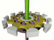
The input shaft drives an eccentric bearing that in turn drives the cycloidal disc in an eccentric, cycloidal motion. The perimeter of this disc is geared to a stationary ring gear and has a series of output shaft pins or rollers placed through the face of the disc. These output shaft pins directly drive the output shaft as the cycloidal disc rotates. The radial motion of the disc is not translated to the output shaft.
Theory of operation
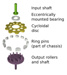
The input shaft is mounted eccentrically to a Rolling-element bearing (typically a cylindrical roller bearing), causing the cycloidal disc to move in a circle. The cycloidal disc will independently rotate around the bearing as it is pushed against the ring gear. This is similar to planetary gears, and the direction of rotation is opposite to that of the input shaft.
The number of pins on the ring gear is larger than the number of pins on the cycloidal disc. This causes the cycloidal disc to rotate around the bearing faster than the input shaft is moving it around, giving an overall rotation in the direction opposing the rotation of the input shaft.
The cycloidal disc has holes that are slightly larger than the output roller pins that go inside them. The output pins will move around in the holes to achieve steady rotation of the output shaft from the wobbling movement of the cycloidal disc.
The reduction rate of the cycloidal drive is obtained from the following formula, where P means the number of the ring gear pins and L is the number of lobes on the cycloidal disc.

Single stage efficiency approaches 93% and double stage approaches 86%.[2] Single stage reductions are available commercially up to 119:1 and double stage up to 7,569:1 [3]
The cycloid disc is usually designed with a shortened cycloid in order to minimize the eccentricity of the disc and the associated unbalance forces at high speeds[4]. For this reason, two cycloid discs are often mounted offset by 180°.
Many modern precision drives provide the eccentric motion through multiple shafts that also transmit the output force, typically 2 to 5 shafts arranged in the same circular pattern as the output rollers of the most basic design, the shafts are driven through planetary-like gears by a central input shaft. Since these shafts are always aligned by the input gears this allows the output to be transmitted through roller bearings rather than intermittent surface contact. Due to the planetary input this is effectively a two-stage drive and may be designed to be directly driven by a high speed brushless motor, this type is often used in robot actuators.
Disadvantages
Due to the eccentric nature of the drive, if the cycloidal disk is not balanced by a second disk or a counterweight, it will generate vibration which will propagate through the driven shafts and the body. This will cause increased wear on the exterior teeth of the cycloidal disk, as well as component bearings. With two discs the static imbalance is corrected but a small dynamic imbalance remains, this is generally considered acceptable for most applications but to reduce vibration high speed drives use three (or more) discs to allow the imbalance to be corrected, the outer discs move in unison and in opposition to the middle one which is twice as massive.
Advantages
Cycloidal drives can start with zero backlash and high torque capacity while compact in size, unlike Involute gearboxes. They are useful in situations where low speed with high torque capacity is needed. Cycloidal drives may be designed with significantly higher contact areas for their size than any gear-based transmission such as epicyclic gears, applying force through many of the 'teeth' at once, allowing very high torque output for the size of the drive at the cost of utilising sliding contact.
See also
- Epicyclic gearing
- Cycloid gear – A gear tooth shape based on the cycloid
- Harmonic drive
References
- Archived December 19, 2008, at the Wayback Machine
- "DARALI CYCLOIDAL REDUCERS". Darali.com. Retrieved 2013-12-04.
- "Cyclo® 6000". www.sumitomodrive.com. Retrieved 2013-08-31.
- tec-science (2019-01-14). "How does a cycloidal drive work?". tec-science. Retrieved 2019-11-05.
External links
| Wikimedia Commons has media related to Cycloidal gears. |