Spot welding
Spot welding (or resistance spot welding[1]) is a type of electric resistance welding used to weld various sheet metal products, through a process in which contacting metal surface points are joined by the heat obtained from resistance to electric current.

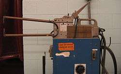
The process uses two shaped copper alloy electrodes to concentrate welding current into a small "spot" and to simultaneously clamp the sheets together. Work-pieces are held together under pressure exerted by electrodes. Typically the sheets are in the 0.5 to 3 mm (0.020 to 0.118 in) thickness range. Forcing a large current through the spot will melt the metal and form the weld. The attractive feature of spot welding is that much energy can be delivered to the spot in a very short time (approximately 10–100 milliseconds).[2] That permits the welding to occur without excessive heating of the remainder of the sheet.
The amount of heat (energy) delivered to the spot is determined by the resistance between the electrodes and the magnitude and duration of the current.[3] The amount of energy is chosen to match the sheet's material properties, its thickness, and type of electrodes. Applying too little energy will not melt the metal or will make a poor weld. Applying too much energy will melt too much metal, eject molten material, and make a hole rather than a weld.[4] Another feature of spot welding is that the energy delivered to the spot can be controlled to produce reliable welds.
Process and equipment

Spot welding involves three stages; the first of which involves the electrodes being brought to the surface of the metal and applying a slight amount of pressure. The current from the electrodes is then applied briefly after which the current is removed but the electrodes remain in place for the material to cool. Weld times range from 0.01 sec to 0.63 sec depending on the thickness of the metal, the electrode force and the diameter of the electrodes themselves.
The equipment used in the spot welding process consists of tool holders and electrodes. The tool holders function as a mechanism to hold the electrodes firmly in place and also support optional water hoses that cool the electrodes during welding. Tool holding methods include a paddle-type, light duty, universal, and regular offset. The electrodes generally are made of a low resistance alloy, usually copper, and are designed in many different shapes and sizes depending on the application needed.
The two materials being welded together are known as the workpieces and must conduct electricity. The width of the workpieces is limited by the throat length of the welding apparatus and ranges typically from 5 to 50 inches (13 to 130 cm). Workpiece thickness can range from 0.008 to 1.25 inches (0.20 to 32 mm).[5]
After the current is removed from the workpiece, it is cooled via the coolant holes in the center of the electrodes. Both water and a brine solution may be used as coolants in spot welding mechanisms.
In the case of resistance spot welding, there are two main parts of the tooling system, the features of which fundamentally influence the whole process: the gun and its type, and the size and shape of the electrode. In such application, where the gun layout should be as rigid as possible due to the high applying forces (e.g. welding of thick materials), the C-type gun is widely used. As well as the high resulting rigidity, this arrangement leads to a high tooling flexibility, as the motion of the electrodes is collinear. Unlike the C-type, the so-called X-type arrangement provides less rigidity, although the reachable workspace is far larger than with the C-type, thus this layout is very common, where thin and flat objects are being processed (e.g. manufacturing of floor pan or roof panel). However, it offers less flexibility in terms of tooling, because the paths of the moving electrodes are not collinear (like the tips of a scissor), so a dome-shaped electrode tip should be used.
Electrodes used in spot welding can vary greatly with different applications. Each tool style has a different purpose. Radius style electrodes are used for high heat applications, electrodes with a truncated tip for high pressure, eccentric electrodes for welding corners, offset eccentric tips for reaching into corners and small spaces, and finally offset truncated for reaching into the workpiece itself.
Characteristics
The spot welding process tends to harden the material, causing it to warp. This reduces the material's fatigue strength, and may stretch the material as well as anneal it. The physical effects of spot welding include internal cracking, surface cracks and a bad appearance. The chemical properties affected include the metal's internal resistance and its corrosive properties.
Welding times are often very short, which can cause problems with the electrodes—they cannot move fast enough to keep the material clamped. Welding controllers will use a double pulse to get around this problem. During the first pulse, the electrode contact may not be able to make a good weld. The first pulse will soften the metal. During the pause between the two pulses, the electrodes will come closer and make better contact.
During spot welding, the large electric current induces a large magnetic field, and the electric current and magnetic field interact with each other to produce a large magnetic force field too, which drives the melted metal to move very fast at a velocity up to 0.5 m/s. As such, the heat energy distribution in spot welding could be dramatically changed by the fast motion of the melted metal.[6][7][8] The fast motion in spot welding can be observed with high speed photography.[9]
The basic spot welder consists of a power supply, an energy storage unit (e.g., a capacitor bank), a switch, a welding transformer, and the welding electrodes. The energy storage element allows the welder to deliver high instantaneous power levels. If the power demands are not high, then the energy storage element isn't needed. The switch causes the stored energy to be dumped into the welding transformer. The welding transformer steps down the voltage and steps up the current. An important feature of the transformer is it reduces the current level that the switch must handle. The welding electrodes are part of the transformer's secondary circuit. There is also a control box that manages the switch and may monitor the welding electrode voltage or current.
The resistance presented to the welder is complicated.[10] There is the resistance of secondary winding, the cables, and the welding electrodes. There is also the contact resistance between the welding electrodes and the workpiece. There is the resistance of the workpieces, and the contact resistance between the workpieces.
At the beginning of the weld, the contact resistances are usually high, so most of the initial energy will be dissipated there. That heat and the clamping force will soften and smooth out the material at the electrode-material interface and make better contact (that is, lower the contact resistance). Consequently, more electrical energy will go into the workpiece and the junction resistance of the two workpieces. As electrical energy is delivered to the weld and causes the temperature to rise, the electrodes and the workpiece are conducting that heat away. The goal is to apply enough energy so that a portion of material within the spot melts without having the entire spot melt. The perimeter of the spot will conduct away much heat and keep the perimeter at a lower temperature. The interior of the spot has less heat conducted away, so it melts first. If the welding current is applied too long, the entire spot melts, the material runs out or otherwise fails, and the "weld" becomes a hole.
The voltage needed for welding depends on the resistance of the material to be welded, the sheet thickness and desired size of the nugget. When welding a common combination like 1.0 + 1.0 mm sheet steel, the voltage between the electrodes is only about 1.5 V at the start of the weld but can fall as low as 1 V at the end of the weld. This decrease in voltage results from the reduction in resistance caused by the workpiece melting. The open circuit voltage from the transformer is higher than this, typically in the 5 to 22 volt range.[11]
The resistance of the weld spot changes as it flows and liquefies. Modern welding equipment can monitor and adjust the weld in real-time to ensure a consistent weld. The equipment may seek to control different variables during the weld, such as current, voltage, power, or energy.
Welder sizes range from 5 to 500 kVA.[12] Micro spot welders, used in a variety of industries, can go down to 1.5 kVA or less for precision welding needs.
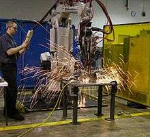
It is common for a spray of molten metal droplets (sparks) to be ejected from the area of the weld during the process.
Resistance spot welding generates no bright arc, so UV protection is not required. OSHA requires transparent face shields or goggles for splatter protection, but does not require any filter lens.[13]
Applications

Spot welding is typically used when welding particular types of sheet metal, welded wire mesh or wire mesh. Thicker stock is more difficult to spot weld because the heat flows into the surrounding metal more easily. Spot welding can be easily identified on many sheet metal goods, such as metal buckets. Aluminium alloys can be spot welded, but their much higher thermal conductivity and electrical conductivity requires higher welding currents. This requires larger, more powerful, and more expensive welding transformers.
Perhaps the most common application of spot welding is in the automobile manufacturing industry, where it is used almost universally to weld the sheet metal to form a car. Spot welders can also be completely automated, and many of the industrial robots found on assembly lines are spot welders (the other major use for robots being painting).
Spot welding is also used in the orthodontist's clinic, where small-scale spot welding equipment is used when resizing metal "molar bands" used in orthodontics.
Another application is spot welding straps to nickel–cadmium, nickel–metal hydride or Lithium-ion battery cells to make batteries. The cells are joined by spot welding thin nickel straps to the battery terminals. Spot welding can keep the battery from getting too hot, as might happen if conventional soldering were done.
Good design practice must always allow for adequate accessibility. Connecting surfaces should be free of contaminants such as scale, oil, and dirt, to ensure quality welds. Metal thickness is generally not a factor in determining good welds.
Modifications
Projection welding is a modification of spot welding in which the weld is localized by means of raised sections, or projections, on one or both of the workpieces to be joined. Heat is concentrated at the projections, which permits the welding of heavier sections or the closer spacing of welds. The projections can also serve as a means of positioning the workpieces. Projection welding is often used to weld studs, nuts, and other threaded machine parts to metal plate. It is also frequently used to join crossed wires and bars. This is another high-production process, and multiple projection welds can be arranged by suitable designing and jigging.[14]
See also
- Clinching (metalworking)
- List of welding processes
- Weld quality assurance
References
- Larry F. Jeffus (2002). Welding: Principles and Applications. Cengage Learning. p. 694. ISBN 9781401810467. Retrieved April 18, 2014.
- robot-welding.com Archived January 17, 2010, at the Wayback Machine
- Joule effect, see Joule's laws
- US Patent 4456810, Adaptive Schedule Selective Weld Control, June 1984. "The weld process is stopped ... before the melt exceeds the electrode diameter. Otherwise, an impressive but totally undesired shower of sparks and hot metal will issue from the weld spot."
- Robert H. Todd; Dell K. Allen; Leo Alting (1994). Manufacturing Processes Reference Guide. Industrial Press. ISBN 0831130490.
- YB Li, ZQ Lin, SJ Hu, and GL Chen, "Numerical Analysis of Magnetic Fluid Dynamics Behaviors During Resistance Spot Welding", J. Appl. Phys., 2007, 101(5), 053506
- YB Li, ZQ Lin, Q Shen and XM Lai,Numerical Analysis of Transport Phenomena in Resistance Spot Welding Process, Transactions of the ASME, Journal of Manufacturing Science and Engineering, 2011, 133(3), 031019-1-8
- YB Li, ZY Wei, YT Li, Q Shen, ZQ Lin, Effects of cone angle of truncated electrode on heat and mass transfer in resistance spot welding, International Journal of Heat and Mass Transfer, 2013, 65(10), 400-408
- A. Cunningham, M. L. Begeman, "A Fundamental Study of Project Welding Using High Speed Photography Computer", Welding Journal, 1965, Vol. 44, 381s-384s
- Geoff Shannon, "Advances in Resistance Welding Technology Offer Improved Weld Quality and Reliability for Battery Manufacturers", Battery Power Products & Technology, July/August 2007, Vol 11, Issue 4, .
- S. R. Deb; S. Deb (2010). Robotics Technology and Flexible Automation. Tata McGraw-Hill Education. p. 491. ISBN 9780070077911. Retrieved April 18, 2014.
- George F. Schrader; Ahmad K. Elshennawy (2000). Manufacturing Processes and Materials. SME. p. 311. ISBN 9780872635173. Retrieved April 18, 2014.
- OSHA (March 26, 2012). "Welding, Cutting, and Brazing 1910.252(b)(2)(i)(C)". Occupational Safety and Health Standards. United States Department of Labor. Retrieved October 8, 2018.
- Kugler, A. N. (1977). Fundamentals of Welding. International Correspondence Schools. LCCN 77360317.
External links
| Wikimedia Commons has media related to Spot welding. |
- Spot, projection and wire welding on YouTube (at 8-9mins) by American Welding Society