Soil resistivity
Soil resistivity is a measure of how much the soil resists or conducts electric current. It is a critical factor in design of systems that rely on passing current through the Earth's surface. An understanding of the soil resistivity and how it varies with depth in the soil is necessary to design the grounding system in an electrical substation, or for lightning conductors. It is needed for design of grounding (earthing) electrodes for substations and High-voltage direct current transmission systems. It was formerly important in earth-return telegraphy. It can also be a useful measure in agriculture as a proxy measurement for moisture content.[1][2]
In most substations the earth is used to conduct fault current when there are ground faults on the system. In single wire earth return power transmission systems, the earth itself is used as the path of conduction from the end customers (the power consumers) back to the transmission facility. In general there is some value above which the impedance of the earth connection must not rise, and some maximum step voltage which must not be exceeded to avoid endangering people and livestock.
The soil resistivity value is subject to great variation, due to moisture, temperature and chemical content. Typical values are:
- Usual values: from 10 up to 1000 (Ω-m)
- Exceptional values: from 1000 up to 10000 (Ω-m)
The SI unit of resistivity is the Ohm-meter (Ω-m); in the United States the Ohm-centimeter (Ω-cm) is often used instead.[3] One Ω-m is 100 Ω-cm. Sometimes the conductivity, the reciprocal of the resistivity, is quoted instead.
A wide range of typical soil resistivity values can be found in literature. Military Handbook 419 (MIL-HDBK-419A) contains reference tables and formulae for the resistance of various patterns of rods and wires buried in soil of known resistivity. Being copyright free, these numbers are widely copied, sometimes without acknowledgement.
Measurement
Because soil quality may vary greatly with depth and over a wide lateral area, estimation of soil resistivity based on soil classification provide only a rough approximation. Actual resistivity measurements are required to fully qualify the resistivity and its effects on the overall transmission system.
Several methods of resistivity measurement are frequently employed:
For measurement the user can use Grounding resistance tester.
Wenner method

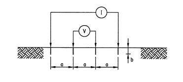
The Wenner four-pin method, as shown in figure above, is the most commonly used technique for soil resistivity measurements.[4][5][6][7] Using the Wenner method, the apparent soil resistivity value is:
where
ρE = measured apparent soil resistivity (Ωm)
a = electrode spacing (m)
b = depth of the electrodes (m)
RW = Wenner resistance measured as "V/I" in Figure (Ω) If b is small compared to a, as is the case of probes penetrating the ground only for a short distance (as normally happens), the previous equation can be reduced to:
Schlumberger method

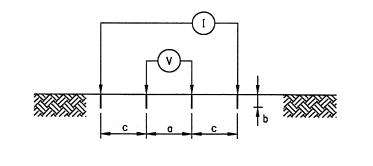
In the Schlumberger method[4][6][7] the distance between the voltages probe is a and the distances from voltages probe and currents probe are c (see figure above).
Using the Schlumberger method, if b is small compared to a and c, and c>2a, the apparent soil resistivity value is:
where
ρE = measured apparent soil resistance (Ωm)
a = electrode spacing (m)
b = depth of the electrodes (m)
c = electrode spacing (m)
RS = Schlumberger resistance measured as "V/I" in Figure (Ω)
Conversion

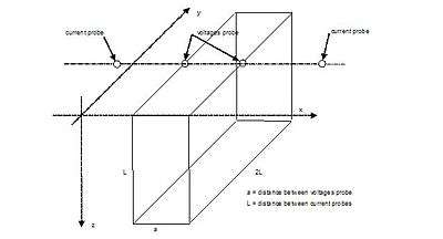
The conversion between values measured using the Schlumberger and Wenner methods is possible only in an approximate way.[7] In any cases, for both Wenner and Schlumberger methods the electrode spacing between the currents probe corresponds to the depth of soil investigation and the measured apparent soil resistivity is referred to a soil volume as in the figure.
The current tends to flow near the surface for small probe spacing, whereas more current penetrates deeper into the soil for large spacing. The resistivity measured for a given current probe spacing represents, to a first approximation, the apparent resistivity of the soil to a depth equal to that spacing.
If the apparent soil resistivity measured with Schlumberger method ρE (with the corresponding electrode spacing aS and c) is given, assuming that the soil resistivity refers to a volume as in the figure with a=L/3 follows:
with
where:
RW = equivalent Wenner resistance (Ω)
aW = equivalent electrode spacing with Wenner method (m)
aS = electrode spacing between voltages probe with Schlumberger method (m)
c = electrode spacing between voltages and currents probe with Schlumberger method (m)
If the measured Schlumberger resistance is given, before calculating the apparent soil resistivity the following factor must be calculated:
The Wenner method is the most widely used method for measuring soil resistivity for electrical grounding (earthing) purposes. The Schlumberger method was developed to increase the voltage signal for the earlier, less sensitive instruments, by placing the potential probes closer to the current probes.
The soil resistivity measurements will be affected by existing nearby grounded electrodes. Buried conductive objects in contact with the soil can invalidate readings made by the methods described if they are close enough to alter the test current flow pattern. This is particularly true for large or long objects.
Variability
Electrical conduction in soil is essentially electrolytic and for this reason the soil resistivity depends on:
- moisture content
- salt content
- temperature (above the freezing point 0 °C)
Because of the variability of soil resistivity, IEC standards require that the seasonal variation in resistivity be accounted for in transmission system design.[9] Soil resistivity can increase by a factor of 10 or more in very cold temperatures. [10]
Corrosion
Soil resistivity is one of the driving factors determining the corrosiveness of soil. The soil corrosiveness is classified based on soil electrical resistivity by the British Standard BS-1377 as follow:
- ρE > 100 Ωm: slightly corrosive
- 50 < ρE < 100 Ωm: moderately corrosive
- 10 < ρE < 50 Ωm: corrosive
- ρE < 10 Ωm: severe
References
- "Precision Farming Tools: Soil Electrical Conductivity" (PDF). Retrieved 12 June 2016.
- "The future of agriculture". The Economist. Retrieved 12 June 2016.
- “IEEE Guide for Measuring Earth Resistivity, Ground Impedance and Earth Surface Potentials of a Ground System”, IEEE Std 81-2012.
- Dias, Rodrigo; dos S. Hoefel, Simone; de A. Costa, Edmondo G.; Carrer, Jose A. M.; de Lacerda, Luiz A. (15 November 2010). "Two-dimensional Simulation of the Wenner Method with the Boundary Element Method - Influence of the Layering Discretization". Mecánica Computacional. XXIX: 2255–2266.
- "Metodi di prospezione Geofisica" (PDF). University of Florence.
- "Guida alla realizzazione dell'impianto di terra". Voltimum.
- Loke, M. H. "Tutorial : 2-D and 3-D electrical imaging survey" (PDF). Stanford University.
- Andolfato, Roberto; Fellin, Lorenzo; Turri, Roberto (4 March 1997). "Analisi di impianti di terra a frequenza industriale: confronto tra indagine sperimentale e simulazione numerica". Energia Elettrica. Milan. 74 (2): 123–134. Archived from the original on 20 August 2011.
- IEC Std 61936-1 "Power Installations Exceeding 1 kV ac – Part 1: Common Rules" Section 10.3.1 General Clause b.
- IEEE Recommended Practice for Grounding of Industrial and Commercial Power Systems, IEEE Std. 142-1982, table 7, page 122