Plough
A plough or plow (US; both /plaʊ/) is a farm tool for loosening or turning the soil before sowing seed or planting.[1] Ploughs were traditionally drawn by oxen and horses, but in modern farms are drawn by tractors. A plough may have a wooden, iron or steel frame, with a blade attached to cut and loosen the soil. It has been fundamental to farming for most of history.[2] The earliest ploughs had no wheels, such a plough being known to the Romans as an aratrum. Celtic peoples first came to use wheeled ploughs in the Roman era.[3]
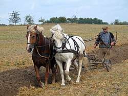
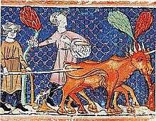
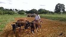
The prime purpose of ploughing is to turn over the uppermost soil,[4] so bringing fresh nutrients to the surface,[5] while burying weeds and crop remains to decay. Trenches cut by the plough are called furrows. In modern use, a ploughed field is normally left to dry and then harrowed before planting. Ploughing and cultivating soil evens the content of the upper 12 to 25 centimetres (5 to 10 in) layer of soil, where most plant-feeder roots grow.
Ploughs were initially powered by humans, but the use of farm animals was considerably more efficient. The earliest beasts used were oxen. Later horses and mules were used in many areas. With the industrial revolution came the possibility of steam engines to pull ploughs. These in turn were superseded by internal-combustion-powered tractors in the early 20th century.
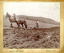
Use of the traditional plough has decreased in some areas threatened by soil damage and erosion. Used instead is shallower ploughing or other less-invasive conservation tillage.
Etymology
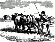
In older English, as in other Germanic languages, the plough was traditionally known by other names, e.g. Old English sulh, Old High German medela, geiza, huohilī(n), Old Norse arðr (Swedish årder), and Gothic hōha, all presumably referring to the ard (scratch plough). The term plough, as used today, was not common until 1700.
The modern word comes from the Old Norse plógr, and is therefore Germanic, but it appears relatively late (it is not attested in Gothic), and is thought to be a loan from one of the north Italic languages. The German cognate is "Pflug", the Dutch "ploeg" and the Swedish "plog". In many Slavic languages and in Romanian the word is "plug". Words with the same root appeared with related meanings: in Raetic plaumorati "wheeled heavy plough" (Pliny, Nat. Hist. 18, 172), and in Latin plaustrum "farm cart", plōstrum, plōstellum "cart", and plōxenum, plōximum "cart box".[6][7] The word must have originally referred to the wheeled heavy plough, common in Roman north-western Europe by the 5th century AD.[8]
Orel (2003)[9] tentatively attaches plough to a PIE stem *blōkó-, which gave Armenian peɫem "to dig" and Welsh bwlch "crack", though the word may not be of Indo-European origin.
Parts

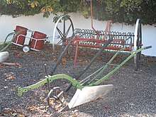
The diagram (right) shows the basic parts of the modern plough:
- beam
- hitch (Brit: hake)
- vertical regulator
- coulter (knife coulter pictured, but disk coulter common)
- chisel (foreshare)
- share (mainshare)
- mouldboard
Other parts not shown or labelled include the frog (or frame), runner, landside, shin, trashboard, and stilts (handles).
On modern ploughs and some older ploughs, the mould board is separate from the share and runner, so these parts can be replaced without replacing the mould board. Abrasion eventually wears out all parts of a plough that come into contact with the soil.
History
Hoeing
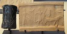
When agriculture was first developed, soil was turned using simple hand-held digging sticks and hoes.[4] These were used in highly fertile areas, such as the banks of the Nile, where the annual flood rejuvenates the soil, to create drills (furrows) in which to plant seeds. Digging sticks, hoes and mattocks were not invented in any one place, and hoe cultivation must have been common everywhere agriculture was practised. Hoe-farming is the traditional tillage method in tropical or sub-tropical regions, which are marked by stony soils, steep slope gradients, predominant root crops, and coarse grains grown at wide distances apart. While hoe-agriculture is best suited to these regions, it is used in some fashion everywhere. Instead of hoeing, some cultures use pigs to trample the soil and grub the earth.
Ard
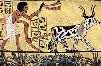
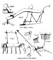
Some ancient hoes, like the Egyptian mr, were pointed and strong enough to clear rocky soil and make seed drills, which is why they are called hand-ards. However, domestication of oxen in Mesopotamia and the Indus valley civilization, perhaps as early as the 6th millennium BC, provided mankind with the draft power needed to develop the larger, animal-drawn true ard (or scratch plough). The earliest surviving evidence of ploughing, has been dated to 3500–3800 BCE, on a site in Bubeneč, Czech Republic.[11] A ploughed field, from c.2800 BCE, has also discovered at Kalibangan, Pakistan.[12] A terracotta model of the early ards was found at Banawali, Pakistan, giving insight into the form of the tool used.[13] The ard remained easy to replace if it became damaged and easy to replicate.[14]
The earliest was the bow ard, which consists of a draft-pole (or beam) pierced by a thinner vertical pointed stick called the head (or body), with one end being the stilt (handle) and the other a share (cutting blade) dragged through the topsoil to cut a shallow furrow suitable for most cereal crops. The ard does not clear new land well, so hoes or mattocks had to be used to pull up grass and undergrowth, and a hand-held, coulter-like ristle could be made to cut deeper furrows ahead of the share. Because the ard left a strip of undisturbed earth between furrows, the fields were often cross-ploughed lengthwise and breadth-wise, which tended to form squarish Celtic fields.[15]:42 The ard is best suited to loamy or sandy soils that are naturally fertilised by annual flooding, as in the Nile Delta and Fertile Crescent, and to a lesser extent any other cereal-growing region with light or thin soil. By the late Iron Age, ards in Europe were commonly fitted with coulters.
Mould-board plough
.jpg)
To grow crops regularly in less-fertile areas, it was once believed that the soil must be turned to bring nutrients to the surface. A major advance for this type of farming was the turn plough, also known as the mould-board plough (UK), moldboard plow (US), or frame-plough. A coulter (or skeith) could be added to cut vertically into the ground just ahead of the share (in front of the frog), a wedge-shaped cutting edge at the bottom front of the mould board with the landside of the frame supporting the under-share (below-ground component). The mould-board plough introduced in the 18th century was a major advance in technology.[4]
The upper parts of the frame carry (from the front) the coupling for the motive power (horses), the coulter and the landside frame. Depending on the size of the implement, and the number of furrows it is designed to plough at one time, a fore-carriage with a wheel or wheels (known as a furrow wheel and support wheel) may be added to support the frame (wheeled plough). In the case of a single-furrow plough there is one wheel at the front and handles at the rear for the ploughman to steer and manœuvre it.
When dragged through a field, the coulter cuts down into the soil and the share cuts horizontally from the previous furrow to the vertical cut. This releases a rectangular strip of sod to be lifted by the share and carried by the mould board up and over, so that the strip of sod (slice of the topsoil) that is being cut lifts and rolls over as the plough moves forward, dropping back upside down into the furrow and onto the turned soil from the previous run down the field. Each gap in the ground where the soil has been lifted and moved across (usually to the right) is called a furrow. The sod lifted from it rests at an angle of about 45 degrees in the adjacent furrow, up the back of the sod from the previous run.
So a series of ploughings runs down a field leaves a row of sods partly in the furrows and partly on the ground lifted earlier. Visually, across the rows, there is the land on the left, a furrow (half the width of the removed strip of soil) and the removed strip almost upside-down lying on about half of the previous strip of inverted soil, and so on across the field. Each layer of soil and the gutter it came from forms a classic furrow.
The mould-board plough greatly reduced the time needed to prepare a field and so allowed a farmer to work a larger area of land. In addition, the resulting pattern of low (under the mould board) and high (beside it) ridges in the soil forms water channels, allowing the soil to drain. In areas where snow build-up causes difficulties, this lets farmers plant the soil earlier, as the snow run-off drains away more quickly.
There are five major parts of a mouldboard plough:
- Mouldboard
- Share
- Landside (short or long)
- Frog (sometimes called a standard)
- Tailpiece
Share, landside, mould board are bolted to the frog, which is an irregular piece of cast iron at the base of the plough body, to which the soil-wearing parts are bolted.
The share is the edge that makes the horizontal cut to separate the furrow slice from the soil below. Conventional shares are shaped to penetrate soil efficiently; the tip is pointed downward to pull the share into the ground to a regular depth. The clearance, usually referred to as suction or down suction, varies with different makes and types of plough. Share configuration is related to soil type, particularly in the down suction or concavity of its lower surface. Generally three degrees of clearance or down suction are recognized: regular for light soil, deep for ordinary dry soil, and double-deep for clay and gravelly soils.
As the share wears away, it becomes blunt and the plough will require more power to pull it through the soil. A plough body with a worn share will not have enough "suck" to ensure it delves the ground to its full working depth.
In addition, the share has horizontal suction related to the amount its point is bent out of line with the land side. Down suction causes the plough to penetrate to proper depth when pulled forward, while horizontal suction causes the plough to create the desired width of furrow. The share is a plane part with a trapezoidal shape. It cuts the soil horizontally and lifts it. Common types are regular, winged-plane, bar-point, and share with mounted or welded point. The regular share conserves a good cut but is recommended on stone-free soils. The winged-plane share is used on heavy soil with a moderate amount of stones. The bar-point share can be used in extreme conditions (hard and stony soils). The share with a mounted point is somewhere between the last two types. Makers have designed shares of various shapes (trapesium, diamond, etc.) with bolted point and wings, often separately renewable. Sometimes the share-cutting edge is placed well in advance of the mould board to reduce the pulverizing action of the soil.
The mould board is the part of the plough that receives the furrow slice from the share.[4] It is responsible for lifting and turning the furrow slice and sometimes for shattering it, depending on the type of mould board, ploughing depth and soil conditions. The intensity of this depends on the type of mould board. To suit different soil conditions and crop requirements, mould boards have been designed in different shapes, each producing its own furrow profile and surface finish, but basically they still conform to the original plough body classification. The various types have been traditionally classified as general purpose, digger, and semi-digger, as described below.
- The general-purpose mould board. This has a low draft body with a gentle, cross-sectional convex curve from top to bottom, which turns a furrow three parts wide by two parts deep, e. g. 300 mm (12 in) wide by 200 mm (7.9 in) deep. It turns the furrow slice slowly almost without breaking it, and is normally used for shallow ploughing (maximum 200 mm (7.9 in) depth). It is useful for grassland ploughing and sets up the land for weathering by winter frosts, which reduces the time taken to prepare a seedbed for spring sown crops.
- The digger mould board is short, abruptly curved with a concave cross-section both from top to bottom and from shin to tail. It turns the furrow slice rapidly, giving maximum shatter, deeper than its width. It is normally used for very deep ploughing (300 mm (12 in) deep or more). It has a higher power requirement and leaves a very broken surface. Digger ploughs are mainly used for land for potatoes and other root crops.
- The semi-digger mould board is a bit shorter than the general-purpose mould board, but with a concave cross-section and a more abrupt curve. Being intermediate between the two mould boards described above, it has a performance that comes in between (approximately 250 mm (9.8 in) deep), with less shattering than the digger mouldboard. It turns an almost square-sectioned furrow and leaves a more broken surface finish. Semi-digger mould boards can be used at various depths and speeds, which suits them for most of the general ploughing on a farm.
- In addition, slatted mould boards are preferred by some farmers, though they are a less common type. They consist of a number of curved steel slats bolted to the frog along the length of the mould board, with gaps between the slats. They tend to break up the soil more than a full mould oard and improve soil movement across the mould board when working in sticky soils where a solid mould board does not scour well.
The land side is the flat plate which presses against and transmits the lateral thrust of the plough bottom to the furrow wall. It helps to resist the side pressure exerted by the furrow slice on the mould board. It also helps to stabilize the plough while in operation. The rear bottom end of the landslide, which rubs against the furrow sole, is known as the heel. A heel iron is bolted to the end of the rear of the land side and helps to support the back of the plough. The land side and share are arranged to give a "lead" towards the unploughed land, so helping to sustain the correct furrow width. The land side is usually made of solid medium-carbon steel and is very short, except at the rear bottom of the plough. The heel or rear end of the rear land side may be subject to excessive wear if the rear wheel is out of adjustment, and so a chilled iron heel piece is frequently used. This is inexpensive and can be easily replaced. The land side is fastened to the frog by plough bolts.
The frog (standard) is the central part of the plough bottom to which the other components of the bottom are attached. It is an irregular piece of metal, which may be made of cast iron for cast iron ploughs or welded steel for steel ploughs. The frog is the foundation of the plough bottom. It takes the shock resulting from hitting rocks, and therefore should be tough and strong. The frog is in turn fastened to the plough frame.
A runner extending from behind the share to the rear of the plough controls the direction of the plough, because it is held against the bottom land-side corner of the new furrow being formed. The holding force is the weight of the sod, as it is raised and rotated, on the curved surface of the mould board. Because of this runner, the mould board plough is harder to turn around than the scratch plough, and its introduction brought about a change in the shape of fields – from mostly square fields into longer rectangular "strips" (hence the introduction of the furlong).
An advance on the basic design was the iron ploughshare, a replaceable horizontal cutting surface mounted on the tip of the share. The earliest ploughs with a detachable and replaceable share date from around 1000 BC in the Ancient Near East,[16] and the earliest iron ploughshares from about 500 BC in China.[17] Early mould boards were wedges that sat inside the cut formed by the coulter, turning over the soil to the side. The ploughshare spread the cut horizontally below the surface, so that when the mould board lifted it, a wider area of soil was turned over. Mould boards are known in Britain from the late 6th century onwards.[18]
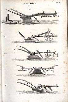
The mould-board plough type is usually set by the method with which the plough is attached to the tractor and the way it is lifted and carried. The basic types are:
- Three wheel trailing type – attached to the standard tractor draw bar and carried on its own three wheels
- Mounted or integra – most use a three-point hitch and have a rear wheel in use only when ploughing. Some also have a gauge wheel to regulate maximum depth.
- Semi-mounted – used principally for larger ploughs. These have a rear wheel which usually carries weight and side thrust when ploughing and sometimes the weight of the rear end of the plough when lifted. The front end of the plough is carried on the tractor lower or draft links.
Plough wheel
- The gauge wheel is an auxiliary wheel to maintain uniform depths of ploughing in various soil conditions. It is usually placed in a hanging position.
- The land wheel of the plough runs on the ploughed land.
- The front or rear furrow wheel of the plough runs in the furrow.
Plough protective devices
When a plough hits a rock or other solid obstruction, serious damage may result unless the plough is equipped with some safety device. The damage may be bent or broken shares, bent standards, beams or braces.
The three basic types of safety devices used on mould-board ploughs are a spring release device in the plough drawbar, a trip beam construction on each bottom, and an automatic reset design on each bottom.
The spring release was used in the past almost universally on trailing-type ploughs with one to three or four bottoms. It is not practical on larger ploughs. When an obstruction is encountered, the spring release mechanism in the hitch permits the plough to uncouple from the tractor. When a hydraulic lift is used on the plough, the hydraulic hoses will also usually uncouple automatically when the plough uncouples. Most plough makers offer an automatic reset system for tough conditions or rocky soils. The re-set mechanism allows each body to move rearward and upward to pass without damage over obstacles such as rocks hidden below soil surface. A heavy leaf or coil-spring mechanism that holds the body in its working position under normal conditions resets the plough after the obstruction is passed.
Another type of auto-reset mechanism uses an oil (hydraulic) and gas accumulator. Shock loads cause the oil to compress the gas. When the gas expands again, the leg returns to its working ploughing position after passing over the obstacle. The simplest mechanism is a breaking (shear) bolt that needs replacement. Shear bolts that break when a plough body hits an obstruction are a cheaper overload protection device. It is important to use the correct replacement bolt.
Trip-beam ploughs are constructed with a hinge point in the beam. This is usually located some distance above the top of the plough bottom. The bottom is held in normal ploughing position by a spring-operated latch. When an obstruction is encountered, the entire bottom is released and hinges back and up to pass over the obstruction. It is necessary to back up the tractor and plough to reset the bottom. This construction is used to protect the individual bottoms. The automatic reset design has only recently been introduced on US ploughs, but has been used extensively on European and Australian ploughs. Here the beam is hinged at a point almost above the point of the share. The bottom is held in the normal position by a set of springs or a hydraulic cylinder on each bottom.
When an obstruction is encountered, the plough bottom hinges back and up in such a way as to pass over the obstruction, without stopping the tractor and plough. The bottom automatically returns to normal ploughing position as soon as the obstruction is passed, without any interruption of forward motion. The automatic reset design permits higher field efficiencies since stopping for stones is practically eliminated. It also reduces costs for broken shares, beams and other parts. The fast resetting action helps produce a better job of ploughing, as large areas of unploughed land are not left, as they are when lifting a plough over a stone.
Loy ploughing
Manual loy ploughing was a form used on small farms in Ireland where farmers could not afford more, or on hilly ground that precluded horses.[19] It was used up until the 1960s in poorer land.[20] It suited the moist Irish climate, as the trenches formed by turning in the sods provided drainage. It allowed potatoes to be grown in bogs (peat swamps) and on otherwise unfarmed mountain slopes.[21][22]
Heavy ploughs
In the basic mould-board plough, the depth of cut is adjusted by lifting against the runner in the furrow, which limited the weight of the plough to what a ploughman could easily lift. This limited the construction to a small amount of wood (although metal edges were possible). These ploughs were fairly fragile and unsuitable for the heavier soils of northern Europe. The introduction of wheels to replace the runner allowed the weight of the plough to increase, and in turn the use of a larger mould-board faced in metal. These heavy ploughs led to greater food production and eventually a marked population increase, beginning around AD 1000.[23]
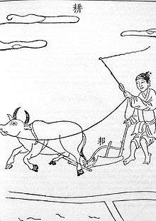
Before the Han Dynasty (202 BC – AD 220), Chinese ploughs were made almost wholly of wood except for the iron blade of the ploughshare. By the Han period the entire ploughshare was made of cast iron. These are the earliest known heavy, mould-board iron ploughs.[17][24]
The Romans achieved a heavy-wheeled mould-board plough in the late 3rd and 4th century AD, for which archaeological evidence appears, for instance, in Roman Britain.[25] The first indisputable appearance after the Roman period is in a northern Italian document of 643.[15]:50 Old words connected with the heavy plough and its use appear in Slavic, suggesting possible early use in that region.[15]:49ff General adoption of the carruca heavy plough in Europe seems to have accompanied adoption of the three-field system in the later 8th and early 9th centuries, leading to improved agricultural productivity per unit of land in northern Europe.[15]:69–78 This was accompanied by larger fields, known variously as carucates, ploughlands, and plough gates.
Improved designs
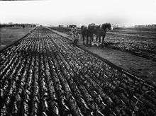
The basic plough with coulter, ploughshare and mould board remained in use for a millennium. Major changes in design spread widely in the Age of Enlightenment, when there was rapid progress in design. Joseph Foljambe in Rotherham, England, in 1730, used new shapes based on the Rotherham plough, which covered the mould board with iron.[26] Unlike the heavy plough, the Rotherham, or Rotherham swing plough consisted entirely of the coulter, mould board and handles. It was much lighter than earlier designs and became common in England. It may have been the first plough widely built in factories and commercially successful there.[27]
In 1789 Robert Ransome, an iron founder in Ipswich, started casting ploughshares in a disused malting at St Margaret's Ditches. A broken mould in his foundry caused molten metal to come into contact with cold metal, making the metal surface extremely hard. This process, chilled casting, resulted in what Ransome advertised as "self-sharpening" ploughs. He received patents for his discovery.
James Small further advanced the design. Using mathematical methods, he eventually arrived at a shape cast from a single piece of iron, an improvement on the Scots plough of James Anderson of Hermiston.[28] A single-piece cast-iron plough was also developed and patented by Charles Newbold in the United States. This was again improved on by Jethro Wood, a blacksmith of Scipio, New York, who made a three-part Scots plough that allowed a broken piece to be replaced. In 1837 John Deere introduced the first steel plough; it was so much stronger than iron designs that it could work soil in US areas previously thought unsuitable for farming.
Improvements on this followed developments in metallurgy: steel coulters and shares with softer iron mould boards to prevent breakage, the chilled plough (an early example of surface-hardened steel),[29] and eventually mould boards with faces strong enough to dispense with the coulter.
Single-sided ploughing
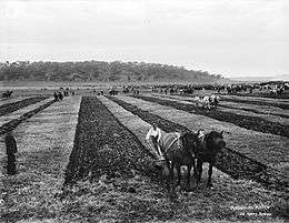
The first mould-board ploughs could only turn the soil over in one direction (conventionally to the right), as dictated by the shape of the mould board. So a field had to be ploughed in long strips, or lands. The plough was usually worked clockwise around each land, ploughing the long sides and being dragged across the short sides without ploughing. The length of the strip was limited by the distance oxen (later horses) could comfortably work without rest, and their width by the distance the plough could conveniently be dragged. These distances determined the traditional size of the strips: a furlong, (or "furrow's length", 220 yards (200 m)) by a chain (22 yards (20 m)) – an area of one acre (about 0.4 hectares); this is the origin of the acre. The one-sided action gradually moved soil from the sides to the centre line of the strip. If the strip was in the same place each year, the soil built up into a ridge, creating the ridge and furrow topography still seen in some ancient fields.
Turn-wrest plough
The turn-wrest plough allows ploughing to be done to either side. The mould board is removable, turning to the right for one furrow, then being moved to the other side of the plough to turn to the left. (The coulter and ploughshare are fixed.) Thus adjacent furrows can be ploughed in opposite directions, allowing ploughing to proceed continuously along the field and so avoid the ridge–furrow topography.
Reversible plough
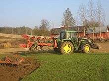
The reversible (or roll-over) plough has two mould-board ploughs mounted back to back, one turning right, the other left. While one works the land, the other is borne upside-down in the air. At the end of each row the paired ploughs are turned over so that the other can be used along the next furrow, again working the field in a consistent direction.
These ploughs date back to the days of the steam engine and the horse. In almost universal use on farms, they have right and left-handed mould boards, enabling them to work up and down the same furrow. Reversible ploughs may either be mounted or semi-mounted and are heavier and more expensive than right-handed models, but have the great advantage of leaving a level surface that facilitates seedbed preparation and harvesting. Very little marking out is necessary before ploughing can start; idle running on the headland is minimal compared with conventional ploughs.
Driving a tractor with furrow-side wheels in the furrow bottom provides the most efficient line of draught between tractor and plough. It is also easier to steer the tractor; driving with the front wheel against the furrow wall will keep the front furrow at the correct width. This is less satisfactory when using a tractor with wide front tyres. Although these make better use of the tractor power, the tyres may compact some of the last furrow slice turned on the previous run. The problem is overcome by using a furrow widener or longer mould board on the rear body. The latter moves the soil further towards the ploughed land, leaving more room for the tractor wheels on the next run.
Driving with all four wheels on unploughed land is another solution to the problem of wide tyres. Semi-mounted ploughs can be hitched in a way that allows the tractor to run on unbroken land and pull the plough in correct alignment without any sideways movement (crabbing).
Riding and multiple-furrow ploughs
Early steel ploughs were walking ploughs, directed by a ploughman holding handles on either side of the plough. Steel ploughs were so much easier to draw through the soil that constant adjustment of the blade to deal with roots or clods was no longer necessary, as the plough could easily cut through them. So not long after that the first riding ploughs appeared, whose wheels kept the plough at an adjustable level above the ground, while the ploughman sat on a seat instead of walking. Direction was now controlled mostly through the draught team, with levers allowing fine adjustments. This led quickly to riding ploughs with multiple mould boards, which dramatically increased ploughing performance.
A single draught horse can normally pull a single-furrow plough in clean light soil, but in heavier soils two horses are needed, one walking on the land and one in the furrow. Ploughs with two or more furrows call for more than two horses, and usually one or more have to walk on the ploughed sod, which is hard going for them and means they tread newly ploughed land down. It is usual to rest such horses every half-hour for about ten minutes.
Heavy volcanic loam soils such as are found in New Zealand require the use of four heavy draught horses to pull a double-furrow plough. Where paddocks are more square than oblong, it is more economical to have horses four wide in harness than two-by-two ahead, so that one horse is always on the ploughed land (the sod). The limits of strength and endurance in horses made greater than two-furrow ploughs uneconomic to use on a farm.
Amish farmers tend to use a team of about seven horses or mules when spring ploughing. As Amish farmers often cooperate on ploughing, teams are sometimes changed at noon. Using this method, about 10 acres (4.0 ha) can be ploughed per day in light soils and about 2 acres (0.81 ha) in heavy soils.
Improving metallurgy and design
John Deere, an Illinois blacksmith, noted that ploughing many sticky, non-sandy soils might benefit from modifications in the design of the mould board and the metals used. A polished needle would enter leather and fabric with greater ease and a polished pitchfork also require less effort. Looking for a polished, slicker surface for a plough, he experimented with portions of saw blades, and by 1837 was making polished, cast steel ploughs. The energy required was lessened, which enabled the use of larger ploughs and more effective use of horse power.
Balance plough

The advent of the mobile steam engine allowed steam power to be applied to ploughing from about 1850. In Europe, soil conditions were often too soft to support the weight of a traction engine. Instead, counterbalanced, wheeled ploughs, known as balance ploughs, were drawn by cables across the fields by pairs of ploughing engines on opposite field edges, or by a single engine drawing directly towards it at one end and drawing away from it via a pulley at the other. The balance plough had two sets of facing ploughs arranged so that with one was in the ground, the other was lifted in the air. When pulled in one direction, the trailing ploughs were lowered onto the ground by the tension on the cable. When the plough reached the edge of the field, the other engine pulled the opposite cable, and the plough tilted (balanced), putting the other set of shares into the ground, and the plough worked back across the field.
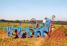
One set of ploughs was right-handed and the other left-handed, allowing continuous ploughing along the field, as with the turn-wrest and reversible ploughs. The man credited with inventing the ploughing engine and associated balance plough in the mid-19th century was John Fowler, an English agricultural engineer and inventor.[30] One notable producer of steam-powered ploughs was J.Kemna of Eastern Prussia, who became the "leading steam plow company on the European continent and penetrated the monopoly of English companies on the world market"[31] at the beginning of the 20th century.
In America the firm soil of the Plains allowed direct pulling with steam tractors, such as the big Case, Reeves or Sawyer-Massey breaking engines. Gang ploughs of up to 14 bottoms were used. Often these were used in regiments of engines, so that in a single field there might be ten steam tractors each drawing a plough. In this way hundreds of acres could be turned over in a day. Only steam engines had the power to draw the big units. When internal combustion engines appeared, they lacked the comparable strength and ruggedness. Only by reducing the number of shares could the work be completed.
Stump-jump plough
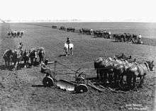
The stump-jump plough, an Australian invention of the 1870s, is designed to break up new farming land that contains tree stumps and rocks expensive to remove. It uses a moveable weight to hold the ploughshare in position. When a tree stump or rock is encountered, the ploughshare is thrown up clear of the obstacle, to avoid breaking its harness or linkage. Ploughing can continue when the weight is returned to the earth.
A simpler, later system uses a concave disc (or pair of them) set at a wide angle to the direction of progress, using a concave shape to hold the disc into the soil – unless something hard strikes the circumference of the disc, causing it to roll up and over the obstruction. As this is dragged forward, the sharp edge of the disc cuts the soil, and the concave surface of the rotating disc lifts and throws the soil to the side. It does not work so well as a mould-board plough (but this is not seen as a drawback, because it helps to fight wind erosion), but it does lift and break up the soil (see disc harrow).
Modern ploughs
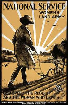
Modern ploughs are usually multiply reversible, mounted on a tractor with a three-point linkage.[32] These commonly have from two and to as many as seven mould boards – and semi-mounted ploughs (whose lifting is assisted by a wheel about halfway along their length) can have as many as 18. The tractor's hydraulics are used to lift and reverse the implement and to adjust furrow width and depth. The ploughman still has to set the draughting linkage from the tractor, so that the plough keeps the proper angle in the soil. This angle and depth can be controlled automatically by modern tractors. As a complement to the rear plough a two or three mould-board plough can be mounted on the front of the tractor if it is equipped with front three-point linkage.
Specialist ploughs
Chisel plough
The chisel plough is a common tool for deep tillage (prepared land) with limited soil disruption. Its main function is to loosen and aerate the soils, while leaving crop residue on top. This plough can be used to reduce the effects of soil compaction and to help break up ploughpan and hardpan. Unlike many other ploughs, the chisel will not invert or turn the soil. This feature has made it a useful addition to no-till and low-till farming practices that attempt to maximise the erosion-preventing benefits of keeping organic matter and farming residues present on the soil surface throughout the year. Thus the chisel plough is considered by some to be more sustainable than other types of plough, such as the mould-board plough.
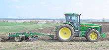
Chisel ploughs are becoming more popular as a primary tillage tool in row-crop farming areas. Basically the chisel plough is a heavy-duty field cultivator intended to operate at depths from 15 cm [6 in] to as much as 46 cm [18 in]. However some models may run much deeper. Each individual plough or shank is typically set from nine inches (229 mm) to twelve inches (305 mm) apart. Such a plough can meet significant soil drag, so that a tractor of sufficient power and traction is required. When planning to plough with a chisel plough, it is important to note that 10–20 horsepower (7.5 to 15 kW) per shank will be required, depending on depth.
Pull-type chisel ploughs are made in working widths from about 2.5 m (8 ft) up to 13.7 m (45 ft). They are tractor mounted, and working depth is hydraulically controlled. Those more than about 4 m (13 ft) wide may be equipped with folding wings to reduce transport width. Wider machines may have the wings supported by individual wheels and hinge joints to allow flexing of the machine over uneven ground. The wider models usually have a wheel each side to control working depth. Three-point hitch-mounted units are made in widths from about 1.5 m to 9 m (5–30 ft).
Cultivators are often similar in form to chisel ploughs, but their goals are different. Cultivator teeth work near the surface, usually for weed control, whereas chisel plough shanks work deep under the surface. So cultivation takes much less power per shank than does chisel ploughing.
Ridging plough
A ridging plough is used for crops such as potatoes or scallions grown buried in ridges of soil, using a technique called ridging or hilling. A ridging plough has two back-to-back mould boards cutting a deep furrow on each pass with high ridges either side. The same plough may be used to split the ridges to harvest the crop.
Scots hand plough
This variety of ridge plough is notable for having a blade pointing towards the operator. It is used solely by human effort rather than with animal or machine assistance and pulled backwards by the operator, requiring great physical effort. It is particularly used for second breaking of ground and for potato planting. It is found in Shetland, some western crofts, and more rarely Central Scotland, typically on holdings too small or poor to merit the use of animals.
Mole plough
The mole plough allows under-drainage to be installed without trenches, or breaks up the deep impermeable soil layers that impede it. It is a deep plough with a torpedo or wedge-shaped tip and a narrow blade connecting it to the body. When dragged over ground, it leaves a channel deep under it that acts as a drain. Modern mole ploughs may also bury a flexible perforated plastic drain pipe as they go, making a more permanent drain – or may be used to lay pipes for water supply or other purposes. Similar machines, so-called pipe-and-cable-laying ploughs, are even used under the sea for laying cables or for preparing the earth for side-scan sonar in a process used in oil exploration.
A simple check can be made to find if the subsoil is in the right condition for mole ploughing. Compact a tennis ball-sized sample from moling depth by hand, then push a pencil through. If the hole stays intact without splitting the ball, the soil is in ideal condition for the mole plough.
Heavy land requires draining to reduce its water content to a level efficient for plant growth. Heavy soils usually have a system of permanent drains, using perforated plastic or clay pipes that discharge into a ditch. Mole ploughs The small tunnels (mole drains) that mole ploughs form lie at a depth of up to 950 mm (3 in) at an angle to the pipe drains. Water from the mole drains seeps into the pipes and runs along them into a ditch.
Mole ploughs are usually trailed and pulled by a crawler tractor, but lighter models for use on the three-point linkage of powerful four-wheel drive tractors are also made. A mole plough has a strong frame that slides along the ground when the machine is at work. A heavy leg, similar to a sub-soiler leg, is attached to the frame and a circular section with a larger diameter expander on a flexible link is bolted to the leg. The bullet-shaped share forms a tunnel in the soil about 75 mm diameter and the expander presses the soil outwards to form a long-lasting drainage channel.
Para-plough
The para-plough, or paraplow, loosens compacted soil layers 3 to 4 dm (12 to 16 inches) deep while maintaining high surface residue levels.[33]It is primary tillage implement for deep ploughing without inversion.
Spade plough
The spade plough is designed to cut the soil and turn it on its side, minimising damage to earthworms, soil microorganism and fungi. This increases the sustainability and long-term fertility of the soil.
Switch plough
Using a bar with square shares mounted perpendicularly and a pivot point to change the bar's angle, the switch plough allows ploughing in either direction. It is best in previously-worked soils, as the ploughshares are designed more to turn the soil over than for deep tillage. At the headland, the operator pivots the bar (and so the ploughshares) to turn the soil to the opposite side of the direction of travel. Switch ploughs are usually lighter than roll-over ploughs, requiring less horsepower to operate.
Effects of mould-board ploughing
Mould-board ploughing in cold and temperate climates, down to 20 cm, aerates the soil by loosening it. It incorporates crop residues, solid manures, limestone and commercial fertilisers along oxygen, so reducing nitrogen losses by denitrification, accelerating mineralisation and raising short-term nitrogen availability for turning organic matter into humus. It erases wheel tracks and ruts from harvesting equipment. It controls many perennial weeds and delays the growth of others until spring. It accelerates spring soil warming and water evaporation due to lower residues on the soil surface. It facilitates seeding with a lighter seed, controls many crop enemies (slugs, crane flies, seedcorn maggots-bean seed flies, borers), and raises the number of "soil-eating" earthworms (endogic), but deters vertical-dwelling earthworms (anecic).
Ploughing leaves little crop residue on the surface that might otherwise reduce both wind and water erosion. Over-ploughing can lead to the formation of hardpan. Typically, farmers break that up with a subsoiler, which acts as a long, sharp knife slicing through the hardened layer of soil deep below the surface. Soil erosion due to improper land and plough utilisation is possible. Contour ploughing mitigates soil erosion by ploughing across a slope, along elevation lines. Alternatives to ploughing, such as a no till method, have the potential to build soil levels and humus. These may be suitable for smaller, intensively cultivated plots and for farming on poor, shallow or degraded soils that ploughing would further degrade.
- Ploughs in art
 Back side of a 100 Mark banknote issued 1908
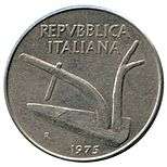 1975 Italian Lira coin
 The Gefion Fountain in Copenhagen
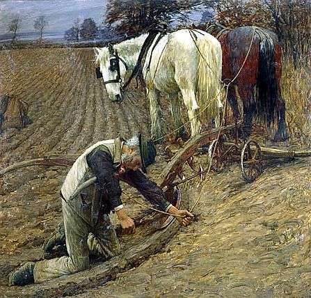 Henry Herbert La Thangue, The Last Furrow, 1895
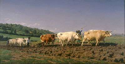 Ploughing in the Nivernais by Rosa Bonheur (1849)
 Plough-usage was revolutionized with the advent of steam-locomotives (as seen in this German 1890's watercolor)
See also
- Boustrophedon (Greek: "ox-turning") — an ancient way of writing, each line being read in the opposite direction like reversible ploughing.
- Conduit current collection
- Foot plough
- Headland (agriculture)
- History of agriculture
- Railroad plough
- Ransome Victory Plough
- Silviculture has a technique for preparing soil for seeding in forests called scarification, which is explained in that article.
- Snowplough
- Whippletree
References
- "Plough". Cambridge English Dictionary. Retrieved 16 September 2018.
- BBC - Anglo-Saxon 7th Century plough coulter found in Kent - 7 April 2011
- Collingwood, R. G.; Collingwood, Robin George; Nowell, John; Myres, Linton (1936). Roman Britain and the English Settlements. Biblo & Tannen Publishers. p. 211. ISBN 9780819611604.
- "Plow". Encyclopaedia Britannica. Retrieved 16 September 2018.
- Sahgal, A C; Sahgal, Mukul. Living Sci. 8 Silver Jubilee. India: Ratna Sagar. p. 7. ISBN 9788183325035.
- C. T. Onions, ed., Oxford Dictionary of English Etymology, s.v. "plough" (Oxford: Clarendon Press, 1996).
- Webster's Encyclopedic Unabridged Dictionary of the English Language, s.v. "plow" (NY: Gramercy Books, 1996).
- Weller, Dr. Judith A. (1999). "Agricultural Use". Roman Traction Systems. Retrieved 20 April 2012.
- Vladimir Orel (2003), A Handbook of Germanic Etymology. Leiden, Netherlands: Brill. s.v. "*plōȝuz".
- Jagor, Fedor (1873). Reisen in den Philippinen. Berlin: Weidmannsche Buchhandlung.
- "Institute of Archeology of CAS report". Archived from the original on 29 August 2018. Retrieved 28 August 2018.
- Lal, BB (2003). Excavations at Kalibangan, the Early Harappans, 1960–1969. Archaeological Survey of India. pp. 17 and 98
- McIntosh, Jane (2008). The Ancient Indus Valley: New Perspectives. ABC-CLIO. p. 121. ISBN 9781576079072.
- "The Plow". Story of Farming.
- Lynn White, Jr., Medieval Technology and Social Change (Oxford: University Press, 1962)
- K. D. White (1984): Greek and Roman Technology, London: Thames and Hudson, p. 59.
- Robert Greenberger, The Technology of Ancient China (New York: Rosen Publishing Group, Inc., 2006), pp. 11–12.
- Hill and Kucharski 1990.
- Paul Hughes (3 March 2011). "Castlepollard venue to host Westmeath ploughing finals". Westmeath Examiner. Archived from the original on 2 October 2011. Retrieved 1 June 2011.
- Patrick Freyne (27 September 2009). "The plough and the stars". Sunday Tribune. Dublin. Archived from the original on 31 March 2012. Retrieved 1 June 2011.
- "The Famine Potato". St Mary's Famine History Museum. Archived from the original on 24 May 2011. Retrieved 1 June 2011.
- Jonathan Bell, "Wooden Ploughs From the Mountains of Mourne, Ireland", Tools & Tillage (1980) 4#1. pp. 46–56; Mervyn Watson, "Common Irish Plough Types and Tillage Techniques", Tools & Tillage (1985) 5#2. pp. 85–98.
- Weber, William (2014). Production, Growth, and the Environment: An Economic Approach. CRC Press. p. 63. ISBN 9781482243062. Retrieved 18 January 2019.
- Wang Zhongshu, trans. by K. C. Chang etc., Han Civilization (New Haven and London: Yale University Press, 1982).
- Evi Margaritis and Martin K. Jones: "Greek and Roman Agriculture", Oleson, John Peter, ed.: The Oxford Handbook of Engineering and Technology in the Classical World, Oxford University Press, 2008, ISBN 978-0-19-518731-1, pp. 158–174 (166, 170).
- A Brief History of The Plough
- "The Rotherham Plough". rotherhamweb.co.uk. Archived from the original on 24 September 2015.
- Wilson, Rick (2015). Scots Who Made America. Birlinn. ISBN 9780857908827. Retrieved 5 April 2015.
- John Deere (1804–1886)
- Archives, The National. "The Discovery Service". discovery.nationalarchives.gov.uk. Retrieved 26 September 2017.
Patent litigation [TR FOW/CO5/116-137] is mainly concerned with a Chancery case of 1863 between John Fowler and his patent assignees in trust against James and Frederick Howard of Bedford for alleged infringement of his patents by the manufacture of balance ploughs.
- Biographie, Deutsche. "Kemna, Julius - Deutsche Biographie". www.deutsche-biographie.de (in German). Retrieved 18 July 2020.
- Blanco-Canqui, Humberto; Lal, Rattan (2008). Principles of Soil Conservation and Management. Springer. p. 198. ISBN 9781402087097.
- "Tillage Equipment" (PDF). Natural Resources Conservation Service. Retrieved 11 June 2012.
Further reading
- Liam Brunt, "Mechanical Innovation in the Industrial Revolution: The Case of Plough Design". Economic History Review (2003) 56#3, pp. 444–477 JSTOR 3698571
- P. Hill and K. Kucharski, "Early Medieval Ploughing at Whithorn and the Chronology of Plough Pebbles", Transactions of the Dumfriesshire and Galloway Natural History and Antiquarian Society, Vol. LXV, 1990, pp 73–83
- V. Sankaran Nair, Nanchinadu: Harbinger of Rice and Plough Culture in the Ancient World
- Wainwright, Raymond P.; Wesley F. Buchele; Stephen J. Marley; William I. Baldwin (1983). "A Variable Approach-Angle Moldboard Plow". Transactions of the ASAE. 26 (2): 392–396. doi:10.13031/2013.33944.
- Steven Stoll, Larding the Lean Earth: Soil and Society in Nineteenth-Century America (New York: Hill and Wang, 2002)
External links
| Look up plough in Wiktionary, the free dictionary. |
| Wikimedia Commons has media related to Ploughs. |
- The Rotherham Plough — the first commercially successful iron plough
- History of the steel plough — as developed by John Deere in the United States
- Breast Ploughs and other antique hand farm tools
- "Tractor Guide Saves Labor for the Farmer", Popular Mechanics, December 1934