Maximum intensity projection
In scientific visualization, a maximum intensity projection (MIP) is a method for 3D data that projects in the visualization plane the voxels with maximum intensity that fall in the way of parallel rays traced from the viewpoint to the plane of projection. This implies that two MIP renderings from opposite viewpoints are symmetrical images if they are rendered using orthographic projection.


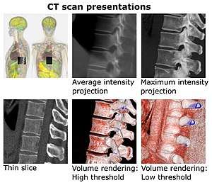
- Average intensity projection
- Maximum intensity projection
- Thin slice (median plane)
- Volume rendering by high and low threshold for radiodensity.
MIP is used for the detection of lung nodules in lung cancer screening programs which use computed tomography scans. MIP enhances the 3D nature of these nodules, making them stand out from pulmonary bronchi and vasculature. MIP imaging is also used routinely by physicians in interpreting Positron Emission Tomography (PET) or Magnetic Resonance Angiography studies.
Additional techniques
This technique is computationally fast, but the 2D results do not provide a good sense of depth of the original data. To improve the sense of 3D, animations are usually rendered of several MIP frames in which the viewpoint is slightly changed from one to the other, thus creating the illusion of rotation. This helps the viewer's perception to find the relative 3D positions of the object components. However, since the projection is orthographic the viewer cannot distinguish between left or right, front or back and even if the object is rotating clockwise or anti-clockwise. Use of depth weighting during production of rotating cines of MIP images can avoid the problem of difficulty of distinguishing right from left, and clockwise vs anti-clockwise rotation.
An easy improvement to MIP is Local maximum intensity projection. In this technique we don't take the global maximum value, but the first maximum value that is above a certain threshold. Because - in general - we can terminate the ray earlier this technique is faster and also gives somehow better results as it approximates occlusion.[1]
History
MIP imaging was invented for use in Nuclear Medicine by Jerold Wallis, MD, in 1988 at Washington University in St Louis, and subsequently published in IEEE Transactions on Medical Imaging.[2] In the setting of Nuclear Medicine, it was originally called MAP (Maximum Activity Projection).[3][4]
| Wikimedia Commons has media related to Maximum intensity projections. |
See also
References
- Sato, Yoshinobu; Shiraga, Nobuyuki; Nakajima, Shin; Tamura, Shinichi; Kikinis, Ron. "Local Maximum Intensity Projection (LMIP". Journal of Computer Assisted Tomography. 22 (6): 912–917. doi:10.1097/00004728-199811000-00014.
- Wallis JW, Miller TR, Lerner CA, Kleerup EC (1989). "Three-dimensional display in nuclear medicine". IEEE Trans Med Imaging. 8 (4): 297–303. doi:10.1109/42.41482. PMID 18230529.
- Wallis JW, Miller TR (1 August 1990). "Volume rendering in three-dimensional display of SPECT images". J. Nucl. Med. 31 (8): 1421–8. PMID 2384811.
- Wallis JW, Miller TR (March 1991). "Three-dimensional display in nuclear medicine and radiology". J Nucl Med. 32 (3): 534–46. PMID 2005466.