MIMO radar
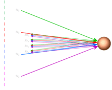
Multiple-input multiple-output (MIMO) radar is an advanced type of phased array radar employing digital receivers and waveform generators distributed across the aperture. MIMO radar signals propagate in a fashion similar to multistatic radar. However, instead of distributing the radar elements throughout the surveillance area, antennas are closely located to obtain better spatial resolution, Doppler resolution, and dynamic range[1]. MIMO radar may also be used to obtain low-probability-of-intercept radar properties[2].

In a traditional phased array system, additional antennas and related hardware are needed to improve spatial resolution. MIMO radar systems transmit mutually orthogonal signals from multiple transmit antennas, and these waveforms can be extracted from each of the receive antennas by a set of matched filters. For example, if a MIMO radar system has 3 transmit antennas and 4 receive antennas, 12 signals can be extracted from the receiver because of the orthogonality of the transmitted signals. That is, a 12-element virtual antenna array is created using only 7 antennas by conducting digital signal processing on the received signals, thereby obtaining a finer spatial resolution compared with its phased array counterpart.
The concept of virtual array

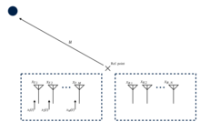
The picture shows a M-by-N MIMO radar system. Suppose that a target is located at u, the transmit antenna is located at and the receive antenna is located at . The received signal at receive antenna can be expressed as:
As mentioned earlier, if {, m=1, ..., M} is an orthogonal set, we can extract M signals from receive antenna, each of which contains the information of an individual transmitting path().
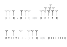
In order to make a comparison between phased array radars and MIMO radars, the relationship between transmit/receive antenna arrays and virtual arrays are discussed in several sources.[3][4] If the placements of the transmit and receive antenna array are expressed as two vectors and respectively, the placement vector of the virtual array is equal to the convolution of and :

Picture above shows the examples of antenna geometry to form a virtual array. In the first example, two uniformly distributed antenna arrays form a 5-element virtual array despite having 6 antennas in total. In the second example, a nine-element virtual array is obtained by increasing the distance between the transmit antennas, implying that a better spatial resolution can be achieved.
To estimate the direction of arrival of the targets according to the N*M signals, methods like MUSIC (algorithm) and maximum likelihood estimation are commonly used with good results.[5][6]
Orthogonal signals

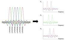
There are a variety of orthogonal signal sets used in the field of MIMO radar. One of the proposed signal sets is the spectrally interleaved multi-carrier signal, which is a modified version of orthogonal frequency-division multiplexing signal[7]. In this approach, the total amount of available subcarriers is distributed among different transmit antennas in an interleaved way.
Another proposed signal set is orthogonal chirp signal, which can be expressed as:
By choosing different initial frequencies , these chirp waveforms can be made orthogonal.[8]
Notes
- Rabideau, D.J. (2003). "Ubiquitous MIMO multifunction digital array radar". The Thirty-Seventh Asilomar Conference on Signals, Systems & Computers. 1: 1057–1064. doi:10.1109/ACSSC.2003.1292087. ISBN 978-0-7803-8104-9.
- Rabideau, D J (2003). Ubiquitous MIMO Multifunction Digital Array Radar ... and the Role of Time-Energy Management in Radar (PDF). DEFENSE TECHNICAL INFORMATION CENTER.
- Bliss, D.W.; Forsythe, K.W. (2003). "Multiple-input multiple-output (MIMO) radar and imaging: degrees of freedom and resolution". The Thirty-Seventh Asilomar Conference on Signals, Systems & Computers, 2003. Pacific Grove, CA, USA: IEEE: 54–59. doi:10.1109/ACSSC.2003.1291865. ISBN 9780780381049.
- K.W Forsythe, D.W. Bliss, and G.S. Fawcett. Multiple-input multiple output (MIMO) radar: performance issues. Conference on Signals, Systems and Computers, 1:310–315, November 2004.
- Gao, Xin, et al. "On the MUSIC-derived approaches of angle estimation for bistatic MIMO radar." Wireless Networks and Information Systems, 2009. WNIS'09. International Conference on. IEEE, 2009.
- Li, Jian, and Petre Stoica. "MIMO radar with colocated antennas." IEEE Signal Processing Magazine 24.5 (2007): 106-114.
- Sturm, Christian, et al. "Spectrally interleaved multi-carrier signals for radar network applications and multi-input multi-output radar." IET Radar, Sonar & Navigation 7.3 (2013): 261-269.
- Chen, Chun-Yang, and P. P. Vaidyanathan. "MIMO radar ambiguity properties and optimization using frequency-hopping waveforms." IEEE Transactions on Signal Processing 56.12 (2008): 5926-5936.