Foy–Breguet telegraph
The Foy–Breguet telegraph, also called the French telegraph,[1] was an electrical telegraph of the needle telegraph type developed by Louis-François-Clement Breguet and Alphonse Foy in the 1840s for use in France. The system used two-needle instruments that presented a display using the same code as that on the optical telegraph of Claude Chappe. The Chappe telegraph was extensively used in France by the government, so this arrangement was appealing to them as it meant there was no need to retrain operators.

Most needle telegraph systems moved the needles by means of an electromagnet driven by battery power applied to the line at the sending end. In contrast, the Foy-Breguet telegraph used electromagnets but they did not directly drive the needle. Instead, they operated the detent of a clockwork mechanism which released the needle to move on one position at a time.
The Chappe telegraph existed in some other countries, but no country besides France tried to duplicate the Chappe telegraph, or any other optical telegraph, as an electrical telegraph. Generally, each electrical telegraph system had a new code developed specifically to suite it. This was problematic for international communications, and in 1855 France abandoned the Foy–Breguet telegraph in favour of the Morse telegraph to bring them into line with the German–Austrian Telegraph Union. Many central European countries were members of this union and they had adopted the Morse system for better interoperability.
Development

The first attempt to bring the electrical telegraph to France was made by Samuel Morse in 1838. He demonstrated his system to the French Academy of Sciences and made a bid for the contract to install a telegraph along the line of the Paris to Saint-Germain railway. However, the French government decided that they did not want to entrust the construction of telegraph lines to private companies. Private operation of telegraph systems had been illegal in France since 1837 and all telegraph infrastructure was owned and operated by the state. Electrical telegraph could only start in France if the government sponsored it. France had the most extensive optical telegraph system of any country, developed for military purposes by Claude Chappe in the revolutionary and Napoleonic periods. There were strong arguments put forward for the superiority of optical telegraphs over electrical telegraphs. Chief amongst these reasons was that electrical systems were vulnerable to attack by saboteurs. In an optical system, only the telegraph stations needed to be defended. An electrical system was impossible to defend over its many hundreds of miles of exposed wires.[2]
Alphonse Foy, the chief administrator of the French telegraphs, had a further objection to the Morse system. He believed that his illiterate telegraph operators would not easily be able to learn the Morse code. He did not, however, entirely reject the electrical telegraph. After the Morse system was rejected in 1839, Foy investigated the Cooke–Wheatstone telegraph in use in England. Foy realised that the needle telegraph displays used by the Cooke–Wheatstone system could be adapted to display the symbols of the French optical telegraph. He asked Louis-François-Clement Breguet to design such a system. It was first tested on the Paris Saint-Cloud to Versailles line in 1842.[3]
Funding for an electrical telegraph was approved in 1844. Foy specified that the new telegraph must show the same display as the Chappe telegraph so that there was no need for operator retraining. This required the display to have three moving parts; the Chappe telegraph had a pivoted crossbar (the regulator) with two moveable arms (the indicators), one at each end of the regulator. A design meeting this requirement was submitted by Pierre-Antoine Joseph Dujardin. Implemented as a needle telegraph, the arrangement required three moving needles, which in turn required three signal wires. The wires were a significant part of the cost of installation; the Morse system, for instance, required only one wire.[4]
In May 1845, Foy ran a comparative test between the Dujardin, Breguet, and Cooke-Wheatstone systems on the Paris, Saint Germain to Rouen line.[5] Foy rejected the Dujardin system in favour of the one by Breguet, even though the Dujardin system more fully mimicked the Chappe system than Breguet's. The Breguet design required only two signal wires, but at the expense of having only two moveable needles. These represented the indicators of the Chappe system. The regulator was simply a marking on the face of the instrument, not a moving part—it was permanently in the horizontal position. The disadvantage of doing this is that it drastically reduced the available codespace which in turn impacted the speed a message could be transmitted.[6]
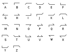
The rejection was perhaps due to the economic reason, or perhaps because Breguet was better acquainted with Foy. Breguet had a long history of working with the French telegraph. His grandfather, Abraham-Louis Breguet, a watchmaker, had worked with Chappe on the design of the optical telegraph and Louis inherited the business. The Chappe system used a large codebook with thousands of predetermined phrases and sentences. 92 codepoints were used to specify the line and page of the codebook (see Telegraph code § Chappe code). There were some early attempts to use a reduced codebook on the Foy–Breguet system, but this was soon dropped in favour of a purely alphabetic code.[7]
France compared to other countries
Many other European countries installed optical telegraphs.[8] Napoleon extended the Chappe system into conquered territories.[9] Other countries developed their own systems, but none of them were as extensive as that in France.[10] Only the system of Abraham Niclas Edelcrantz in Sweden even came close.[11] Consequently, other nations did not have such a strong desire for backward compatibility as France and were able to move to the electrical telegraph sooner. France was unique in requiring the electrical telegraph to mimic the optical telegraph.[12]
Operation

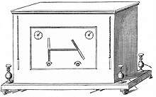
The display of Foy–Breguet telegraph instruments consists of two needles each pivoted at its centre. One half of each needle is coloured black and the other half white. The black part of the needles is meant to represent the indicators of the Chappe telegraph. The white part of the needles is ignored. A bar is marked on the faceplate of the instrument between the pivot points of the needles. This is meant to represent the regulator of the Chappe telegraph, but in the Foy–Breguet system it is purely decorative – it does not move. Each needle can take on any one of eight positions, moving in steps of 45°, resulting in a codespace of 8×8=64 codepoints.[13]
Unlike other needle telegraphs, the motive force that rotates the needles is not provided by the electric current on the telegraph line. Instead, it is provided by a clockwork mechanism that has to be kept wound. The winding keys can be seen in the image of the instrument hanging on chains either side of the instrument face. There is a separate key and a separate mechanism for each needle. When it is desired to wind the mechanism, the key is attached to a square winder situated directly below each needle. When current is applied to one of the telegraph lines, the detent of the corresponding clockwork mechanism is released by means of the armature of an electromagnet and the needle advances by 45°. When the current is cut off the detent is again released and the needle advances a further 45°.[14] The current is applied to both the sending and receiving instrument so that the sending operator can view the resulting transmission.[15]
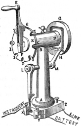
The operator controls the transmission by means of two manipulators. Each of these manipulators has a crank handle which can be set in any one of eight notched positions corresponding to the eight possible positions of one of the needles. As the crank handle is turned through the notches, the battery is alternately connected and disconnected from the line and the local instrument. Thus, current is alternately applied and removed from the mechanism turning the needles.[16]
A drawback of the Foy–Breguet system was that it did not use repeaters over long distances. Other major telegraph systems used relays for this purpose and there were efforts to apply this technology to the French system. This was unsuccessful, which meant that the French system had to employ operators to retransmit messages in some places.[17] The requirement to provide two lines could not be met, or was not economic to meet, on some routes. A single-needle instrument was developed to fill this need. This instrument was mechanically identical to one half of the two-needle version. In fact, it was possible to use one side only of a two-needle instrument with a single line if desired. The coding was the same on the one-needle device except that the positions of the two indicators of each character were sent sequentially instead of in parallel. This reduced the transmission speed to 16–18 wpm.[18]
Connection to England

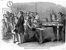
A submarine telegraph cable was laid from England to France by the Submarine Telegraph Company in 1851.[19] In the UK, the Cooke and Wheatstone telegraph was in use which used a different code.[20] This meant that at the English end, both a Foy–Breguet operator and a Cooke–Wheatstone operator were required so that messages could be recoded between the two systems.[21] The Foy–Breguet system was faster to send and read (between 24 and 46 wpm) than the Cooke–Wheatstone. A Foy–Breguet operator could instantly see the letter being transmitted from the visual pattern, whereas the Cooke–Wheatstone operator had to count the left and right deviations of the single needle.[22]
Withdrawal
For a decade France maintained a mixture of optical telegraph and electrical telegraph systems on its network. The Foy-Breguet system ensured that operators could easily be transferred from the optical to the electric systems, although many optical operators (semaphorists) declined to become telegraphists when their lines were updated. The semaphorists were largely rural workers on isolated stations used to taking on the responsibilities of carrying out mechanical repairs by themselves. After all, if the equipment broke down, they no longer had the means to call for assistance. Telegraphists were located in offices with management and service personnel on hand. They were forbidden from attempting any kind of repair and had a more paperwork intensive job. Despite its advantages in the French context, the uniqueness of the French system eventually led to its decline.[23][24]
During the 1850s, as international telegraph traffic grew, having different telegraph systems in different countries became increasingly problematic. Direct connections were not possible and operators had to be employed to recode messages crossing borders. The code that was later to become known as International Morse Code was adopted in several countries. It was first used on Hamburg railways and was devised by Friedrich Clemens Gerke. This code was a heavily modified version of the original American Morse code and was known as the Hamburg code or Gerke code.[25] Gerke's code was adopted in 1851 by the German-Austrian Telegraph Union which represented many central European countries.[26] In 1855, France also adopted the code and replaced the Foy–Breguet telegraph equipment with the Morse system.[27]
References
- Butrica, p. 15
- Holzmann & Pehrson, pp. 92–93
- Huurdeman, p. 72–73
- Holzmann & Pehrson, p. 93
- Huurdeman, p. 73
- Holzmann & Pehrson, pp. 93–94
- Holzmann & Pehrson, pp. 93–94
- Holzmann & Pehrson, p. 179
- Holzmann & Pehrson, pp. 72–73
- Huurdeman, p. 37
- Holzmann & Pehrson, p. x
- Aitken & Foulc, pp. 17–18
- Shaffner, pp. 325–329
- Shaffner, pp. 325–328
- Shaffner, pp. 330–331
- Shaffner, pp. 329–330
- Shaffner, p. 330
- Shaffner, p. 333
- Haigh, p. 193
- Shaffner, p. 221
- Roberts, ch. 13
- Shaffner, pp. 331-332
- Shaffner, p. 325
- Butrica, p. 21
- Coe, p. 69
- Turnbull, p. 77
- Holzmann & Pehrson, p. 94
Bibliography
- Aitken, Frédéric; Foulc, Jean-Numa, From Deep Sea to Laboratory 1, John Wiley & Sons, 2019 ISBN 1786303744.
- Butrica, Andrew J. (1986). From inspecteur to ingénieur: telegraphy and the genesis of electrical engineering in France, 1845-1881 (Thesis Dissertation). Iowa State University. Retrieved 8 March 2020.
- Coe, Lewis, The Telegraph: A History of Morse's Invention and Its Predecessors in the United States, McFarland, 2003 ISBN 0786418087.
- Haigh, Kenneth Richardson, Cableships and Submarine Cables, Adlard Coles, 1968 OCLC 497380538.
- Huurdeman, Anton A., The Worldwide History of Telecommunications, Wiley, 2003 ISBN 0471205052.
- Holzmann, Gerard J.; Pehrson, Björn, The Early History of Data Networks, Wiley, 1995 ISBN 0818667826.
- Roberts, Steven, Distant Writing: A History of the Telegraph Companies in Britain between 1838 and 1868, ch. 13 "The companies abroad", accessed 4 March 2020.
- Shaffner, Taliaferro Preston, The Telegraph Manual, Pudney & Russell, 1859 OCLC 258508686.
- Turnbull, Laurence, The Electro-magnetic Telegraph, A. Hart, 1853 OCLC 60717772.
External links
- Berghen, Fons Vanden, "Louis Breguet et ses appareils télégraphiques", Les Cahiers de la FNARH, pp. 14–25, no. 111, Fédération Nationale des Associations de personnel de La Poste et d'Orange pour la Recherche Historique, 2009 (in French). Includes many photographs of French telegraph instruments.