Control system
A control system manages, commands, directs, or regulates the behavior of other devices or systems using control loops. It can range from a single home heating controller using a thermostat controlling a domestic boiler to large Industrial control systems which are used for controlling processes or machines.
.jpg)
For continuously modulated control, a feedback controller is used to automatically control a process or operation. The control system compares the value or status of the process variable (PV) being controlled with the desired value or setpoint (SP), and applies the difference as a control signal to bring the process variable output of the plant to the same value as the setpoint.
For sequential and combinational logic, software logic, such as in a programmable logic controller, is used.
Open-loop and closed-loop control
There are two common classes of control action: open loop and closed loop. In an open-loop control system, the control action from the controller is independent of the process variable. An example of this is a central heating boiler controlled only by a timer. The control action is the switching on or off of the boiler. The process variable is the building temperature. This controller operates the heating system for a constant time regardless of the temperature of the building.
In a closed-loop control system, the control action from the controller is dependent on the desired and actual process variable. In the case of the boiler analogy, this would utilise a thermostat to monitor the building temperature, and feed back a signal to ensure the controller output maintains the building temperature close to that set on the thermostat. A closed loop controller has a feedback loop which ensures the controller exerts a control action to control a process variable at the same value as the setpoint. For this reason, closed-loop controllers are also called feedback controllers.[1]
Feedback control systems
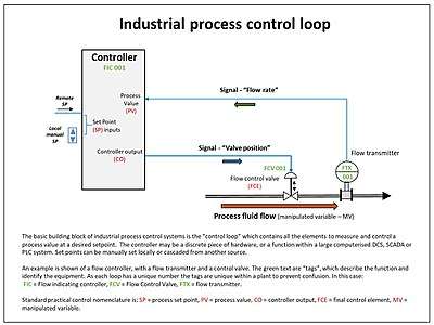
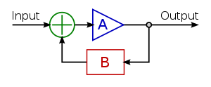
In the case of linear feedback systems, a control loop including sensors, control algorithms, and actuators is arranged in an attempt to regulate a variable at a setpoint (SP). An everyday example is the cruise control on a road vehicle; where external influences such as hills would cause speed changes, and the driver has the ability to alter the desired set speed. The PID algorithm in the controller restores the actual speed to the desired speed in the optimum way, with minimal delay or overshoot, by controlling the power output of the vehicle's engine.
Control systems that include some sensing of the results they are trying to achieve are making use of feedback and can adapt to varying circumstances to some extent. Open-loop control systems do not make use of feedback, and run only in pre-arranged ways.
Logic control
Logic control systems for industrial and commercial machinery were historically implemented by interconnected electrical relays and cam timers using ladder logic. Today, most such systems are constructed with microcontrollers or more specialized programmable logic controllers (PLCs). The notation of ladder logic is still in use as a programming method for PLCs.[2]
Logic controllers may respond to switches and sensors, and can cause the machinery to start and stop various operations through the use of actuators. Logic controllers are used to sequence mechanical operations in many applications. Examples include elevators, washing machines and other systems with interrelated operations. An automatic sequential control system may trigger a series of mechanical actuators in the correct sequence to perform a task. For example, various electric and pneumatic transducers may fold and glue a cardboard box, fill it with product and then seal it in an automatic packaging machine.
PLC software can be written in many different ways – ladder diagrams, SFC (sequential function charts) or statement lists.[3]
On–off control
On–off control uses a feedback controller that switches abruptly between two states. A simple bi-metallic domestic thermostat can be described as an on-off controller. When the temperature in the room (PV) goes below the user setting (SP), the heater is switched on. Another example is a pressure switch on an air compressor. When the pressure (PV) drops below the setpoint (SP) the compressor is powered. Refrigerators and vacuum pumps contain similar mechanisms. Simple on–off control systems like these can be cheap and effective.
Linear control
Linear control systems use negative feedback to produce a control signal to maintain the controlled PV at the desired SP. There are several types of linear control systems with different capabilities.
Proportional control
Proportional control is a type of linear feedback control system in which a correction is applied to the controlled variable which is proportional to the difference between the desired value (SP) and the measured value (PV). Two classic mechanical examples are the toilet bowl float proportioning valve and the fly-ball governor.
The proportional control system is more complex than an on–off control system, but simpler than a proportional-integral-derivative (PID) control system used, for instance, in an automobile cruise control. On–off control will work for systems that do not require high accuracy or responsiveness, but is not effective for rapid and timely corrections and responses. Proportional control overcomes this by modulating the manipulated variable (MV), such as a control valve, at a gain level which avoids instability, but applies correction as fast as practicable by applying the optimum quantity of proportional correction.
A drawback of proportional control is that it cannot eliminate the residual SP–PV error, as it requires an error to generate a proportional output. A PI controller can be used to overcome this. The PI controller uses a proportional term (P) to remove the gross error, and an integral term (I) to eliminate the residual offset error by integrating the error over time.
In some systems there are practical limits to the range of the MV. For example, a heater has a limit to how much heat it can produce and a valve can open only so far. Adjustments to the gain simultaneously alter the range of error values over which the MV is between these limits. The width of this range, in units of the error variable and therefore of the PV, is called the proportional band (PB).
Furnace example
When controlling the temperature of an industrial furnace, it is usually better to control the opening of the fuel valve in proportion to the current needs of the furnace. This helps avoid thermal shocks and applies heat more effectively.
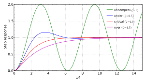
At low gains, only a small corrective action is applied when errors are detected. The system may be safe and stable, but may be sluggish in response to changing conditions. Errors will remain uncorrected for relatively long periods of time and the system is overdamped. If the proportional gain is increased, such systems become more responsive and errors are dealt with more quickly. There is an optimal value for the gain setting when the overall system is said to be critically damped. Increases in loop gain beyond this point lead to oscillations in the PV and such a system is underdamped. Adjusting gain to achieve critically damped behavior is known as tuning the control system.
In the underdamped case, the furnace heats quickly. Once the setpoint is reached, stored heat within the heater sub-system and in the walls of the furnace will keep the measured temperature rising beyond what is required. After rising above the setpoint, the temperature falls back and eventually heat is applied again. Any delay in reheating the heater sub-system allows the furnace temperature to fall further below setpoint and the cycle repeats. The temperature oscillations that an underdamped furnace control system produces are undesirable.
In a critically damped system, as the temperature approaches the setpoint, the heat input begins to be reduced, the rate of heating of the furnace has time to slow and the system avoids overshoot. Overshoot is also avoided in an overdamped system but an overdamped system is unnecessarily slow to initially reach setpoint respond to external changes to the system, e.g. opening the furnace door.
PID control
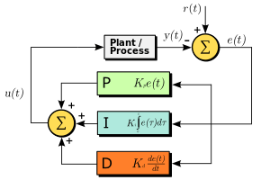
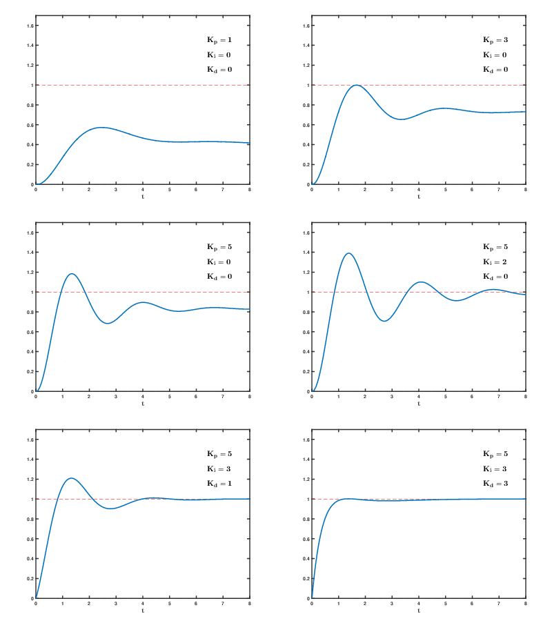
Pure proportional controllers must operate with residual error in the system. Though PI controllers eliminate this error they can still be sluggish or produce oscillations. The PID controller addresses these final shortcomings by introducing a derivative (D) action to retain stability while responsiveness is improved.
Derivative action
The derivative is concerned with the rate-of-change of the error with time: If the measured variable approaches the setpoint rapidly, then the actuator is backed off early to allow it to coast to the required level; conversely, if the measured value begins to move rapidly away from the setpoint, extra effort is applied—in proportion to that rapidity to help move it back.
On control systems involving motion-control of a heavy item like a gun or camera on a moving vehicle, the derivative action of a well-tuned PID controller can allow it to reach and maintain a setpoint better than most skilled human operators. If derivative action is over-applied, it can, however, lead to oscillations.
Integral action
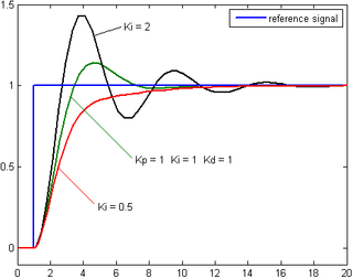
The integral term magnifies the effect of long-term steady-state errors, applying an ever-increasing effort until error is removed. In the example of the furnace above working at various temperatures, if the heat being applied does not bring the furnace up to setpoint, for whatever reason, integral action increasingly moves the proportional band relative to the setpoint until the PV error is reduced to zero and the setpoint is achieved.
Ramp up % per minute
Some controllers include the option to limit the "ramp up % per minute". This option can be very helpful in stabilizing small boilers (3 MBTUH), especially during the summer, during light loads. A utility boiler "unit may be required to change load at a rate of as much as 5% per minute (IEA Coal Online - 2, 2007)".[4]
Other techniques
It is possible to filter the PV or error signal. Doing so can reduce the response of the system to undesirable frequencies, to help reduce instability or oscillations. Some feedback systems will oscillate at just one frequency. By filtering out that frequency, more "stiff" feedback can be applied, making the system more responsive without shaking itself apart.
Feedback systems can be combined. In cascade control, one control loop applies control algorithms to a measured variable against a setpoint, but then provides a varying setpoint to another control loop rather than affecting process variables directly. If a system has several different measured variables to be controlled, separate control systems will be present for each of them.
Control engineering in many applications produces control systems that are more complex than PID control. Examples of such fields include fly-by-wire aircraft control systems, chemical plants, and oil refineries. Model predictive control systems are designed using specialized computer-aided-design software and empirical mathematical models of the system to be controlled.
Hybrid systems of PID and logic control are widely used. The output from a linear controller may be interlocked by logic for instance.
Fuzzy logic
Fuzzy logic is an attempt to apply the easy design of logic controllers to the control of complex continuously varying systems. Basically, a measurement in a fuzzy logic system can be partly true, that is if yes is 1 and no is 0, a fuzzy measurement can be between 0 and 1.
The rules of the system are written in natural language and translated into fuzzy logic. For example, the design for a furnace would start with: "If the temperature is too high, reduce the fuel to the furnace. If the temperature is too low, increase the fuel to the furnace."
Measurements from the real world (such as the temperature of a furnace) are converted to values between 0 and 1 by seeing where they fall on a triangle. Usually, the tip of the triangle is the maximum possible value which translates to 1.
Fuzzy logic, then, modifies Boolean logic to be arithmetical. Usually the "not" operation is "output = 1 - input," the "and" operation is "output = input.1 multiplied by input.2," and "or" is "output = 1 - ((1 - input.1) multiplied by (1 - input.2))". This reduces to Boolean arithmetic if values are restricted to 0 and 1, instead of allowed to range in the unit interval [0,1].
The last step is to "defuzzify" an output. Basically, the fuzzy calculations make a value between zero and one. That number is used to select a value on a line whose slope and height converts the fuzzy value to a real-world output number. The number then controls real machinery.
If the triangles are defined correctly and rules are right the result can be a good control system.
When a robust fuzzy design is reduced into a single, quick calculation, it begins to resemble a conventional feedback loop solution and it might appear that the fuzzy design was unnecessary. However, the fuzzy logic paradigm may provide scalability for large control systems where conventional methods become unwieldy or costly to derive.
Fuzzy electronics is an electronic technology that uses fuzzy logic instead of the two-value logic more commonly used in digital electronics.
Physical implementation
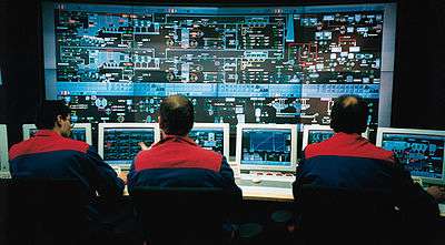
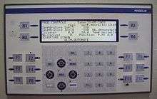
The range of implementation is from compact controllers often with dedicated software for a particular machine or device, to distributed control systems for industrial process control.
Logic systems and feedback controllers are usually implemented with programmable logic controllers.
See also
- Behavior trees (artificial intelligence, robotics and control)
- Building automation
- Coefficient diagram method
- Control engineering
- Control theory
- Cybernetics
- Distributed control system
- Droop speed control
- Education and training of electrical and electronics engineers
- EPICS
- Good regulator
- Hierarchical control system
- HVAC control system
- Industrial control systems
- Motion control
- Networked control system
- Numerical control
- Perceptual control theory
- PID controller
- Process control
- Process optimization
- Programmable logic controller
- Sampled data systems
- SCADA
- VisSim
References
- "Feedback and control systems" - JJ Di Steffano, AR Stubberud, IJ Williams. Schaums outline series, McGraw-Hill 1967
- Kuphaldt, Tony R. "Chapter 6 LADDER LOGIC". Lessons In Electric Circuits -- Volume IV. Archived from the original on 12 September 2010. Retrieved 22 September 2010.
- Brady, Ian. "Programmable logic controllers - benefits and applications" (PDF). PLCs. Archived (PDF) from the original on 2 February 2014. Retrieved 5 December 2011.
- "Energy Efficient Design of Auxiliary Systems in Fossil-Fuel Power Plants" (PDF). ABB. p. 262. Archived (PDF) from the original on 2014-08-05. Retrieved 2014-04-07.
|section=ignored (help)
External links
| Wikibooks has a book on the topic of: Control Systems |
- Semiautonomous Flight Direction - Reference unmannedaircraft.org
- Control System Toolbox for design and analysis of control systems.
- Control Systems Manufacturer Design and Manufacture of control systems.
- Mathematica functions for the analysis, design, and simulation of control systems
- Python Control System (PyConSys) Create and simulate control loops with Python. AI for setting PID parameters.