AGARD-B wind tunnel model
AGARD-B is a standard wind tunnel model (calibration model) that is used to verify, by comparison of test results with previously published data, the measurement chain in a wind tunnel. Together with its derivative AGARD-C it belongs to a family[1] of AGARD standard wind tunnel models. Its origin dates to the year 1952, and the Second Meeting of the AGARD Wind Tunnel and Model Testing Panel in Rome, Italy, when it was decided to define two standard wind tunnel model configurations (AGARD-A and AGARD-B) to be used for exchange of test data and comparison of test results of same models tested in different wind tunnels[2]. The idea was to establish standards of comparison between wind tunnels and improve the validity of wind tunnel tests. Among the standard wind tunnel models, AGARD model configuration B (AGARD-B) has become by far the most popular. Initially intended for the supersonic wind tunnels, the AGARD-B configuration has since been tested in many wind tunnels at a wide range of Mach numbers, from low subsonic (Mach 0.1), through transonic (Mach 0.7 to 1.4) to hypersonic (up to Mach 8 and above). Therefore, a considerable database of test results is available.


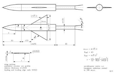
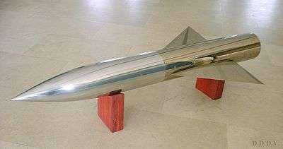
AGARD-B[1] (see figure) is a body-wing configuration. All its dimensions are given in terms of the body diameter "D" so that the model can be produced in any scale, as appropriate for a particular wind tunnel. The body is an 8.5 diameters long solid of revolution consisting of a 5.5 diameters long cylindrical segment and a nose with a length of 3 diameters and having a local radius defined by the equation y = x/3 · [1 - 1/9 · (x/D)2 + 1/54 · (x/D)3].
The wing is a delta in the form of an equilateral triangle with a span of four body diameters. Wing section is a symmetric cylindrical arc with a relative thickness t/c of 4%. Leading and trailing edges of the wing should be rounded with a radius equal to 0.002 D. However, this specification is unclear. It is obvious that the specified radius can not be applied near the wingtips, or large deformations in the plan form of the wing would occur. In the past, this part of the specification was interpreted in different ways by model designers which led to small differences in shapes of the tested models. The recommended solution[2] is to have the leading- and trailing-edge radii of 0.002 D at the theoretical root chord and to decrease the radii towards the wing tips proportionally to the local chord.
A support sting to be used with the AGARD-B model was defined as well. The initial specification[3] of the model called for a sting having a diameter of 0.5 D and a length of 1.5 D. In the revised specification[1] the length of the sting was changed to 3 D in order to reduce sting interference, but at that moment a number of wind tunnel tests had already been made. Therefore, published test results[2] for the AGARD-B models do not all correspond to theoretical model configuration.
The drag characteristics of the AGARD-B model were found to be somewhat sensitive to the boundary layer transition on the model. In order to reduce the scatter of results, in some wind tunnel facilities the model was tested with boundary layer transition trips near the leading edges of the wing and the nose of the body. On the other hand, a number of wind tunnel tests was made without fixed transition. Drag results with and without the fixed boundary layer transition differ, which should not be neglected when comparing test results from different wind tunnel laboratories.
In some wind tunnel laboratories, AGARD-B was tested in non-standard configurations, e.g. as a half-model (half-span model).[4]
Some free-flight tests of the AGARD-B model were performed. For these tests, the standard geometry was modified by adding, at the rear end of the body, two triangular vertical stabilisers, one on the ventral and one on the dorsal side of the body. Size of the vertical stabilizers was 50% of the wing size, i.e. their span was 2.5 D.[5]
AGARD-B standard model is intended primarily for the measurement of aerodynamic forces and moments. Test results are most often presented in the form of nondimensional aerodynamic coefficients in the wind axes system. Reference area for the calculation of the coefficients is the theoretical wing area Sref = 4√3D2. Reference length for the pitching moment coefficient Cm is the mean aerodynamic chord (m.a.c.) equal to 4√3D/3 while the reference length for the yawing and rolling moment coefficients Cn and Cl is the wing span (Bref = 4 D). Moments are reduced to a point in the plane of symmetry of the model, at the longitudinal position of 50% of the m.a.c. (however, in some published results [6], moments were reduced to a point at 25% of the m.a.c.). Drag coefficient is presented in terms of forebody drag Cxf obtained by subtracting, from the total measured drag Cx, the base drag Cxb computed from the measured base pressure on the model. Likewise, Lift coefficient represents forebody lift.
Some laboratories have selected to test the AGARD-B standard model for periodic checkouts of the quality of measurements in their wind tunnels.[7][8]
AGARD-C


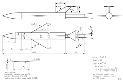
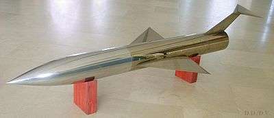
At the AGARD Wind Tunnel and Model Testing Panel meeting in Paris, France, in 1954, it was agreed to add a third model configuration to the family of AGARD calibration models, by extending the body of the AGARD-B by 1.5 diameters and by adding a horizontal and a vertical tail in the T-tail configuration[2]. The horizontal tail has an area equal to 1/6 of the wing area. Sections of the vertical and horizontal tail are circular arc profiles defined identically to the profile of the wing. Forward of the 1.5 D body extension, the geometry of the AGARD-C model is identical to that of the AGARD-B. Also, the position of the moments reduction point (the aerodynamic centre) is the same as on AGARD-B[1].
The support sting for the AGARD-C model is identical to the sting for the AGARD-B model, having a length of 3 D aft of model base and a diameter of 0.5 D.
The longer body of the AGARD-C model and the existence of the tail make it easier to detect (from anomalies in the wind tunnel test results) if the shock waves reflected from the walls of the wind tunnel test section are passing too close to the rear end of the model. The existence of the tail generally makes this model more sensitive than AGARD-B to flow curvature in the wind tunnel test section[2][9].
AGARD-C is primarily used in the transonic wind tunnels and the database of published test results is somewhat smaller than the one for the AGARD-B model.
In order to reduce cost and produce more versatile wind tunnel models, actual designs of AGARD-B and AGARD-C are sometimes realized as an AGARD-B configuration to which a body segment with the T-tail can be attached at the rear end to form the AGARD-C configuration (see figure).
References
- Wind Tunnel Calibration Models, AGARD Specification 2, AGARD, 1958
- Hills R., "A Review of Measurements on AGARD Calibration Models" Archived 2014-07-14 at the Wayback Machine, AGARDograph 64, Aircraft Research Association Bedford, England, 1961
- Specification for AGARD Wind Tunnel Calibration Models, AGARD memorandum, AGARD, 1955
- Aoki Y., Kanda H., Sato M., Nagai S., Itabashi Y., Nishijima H., Kimura T."AGARD-B Standard Model Tests in JAXA 0.8 m by 0.45 m High Reynolds Number Transonic Wind Tunnel", JAXA-SP-09-005, Proceedings of the Wind Technology Association 81st meeting, 2009
- Piland, R.O., "The Zero-Lift Drag of a 60o Delta-Wing-Body Combination (AGARD Model 2) Obtained from Free-Flight Tests Between Mach Numbers 0.8 and 1.7", NACA TN-3081, Langley Aeronautical Laboratory, NACA, 1954
- Anderson C.F., An Investigation of the Aerodynamic Characteristics of the AGARD Model B for Mach Numbers from 0.1 to 1.0, AEDC-TR-70-100, Arnold Engineering Development Center, 1970
- Damljanovic D, Isakovic J. and Rašuo B., "T-38 Wind-Tunnel Data Quality Assurance Based on Testing of a Standard Model", Journal of Aircraft, Vol. 50, No. 4 (2013), pp. 1141-1149. doi: 10.2514/1.C032081
- Damljanovic D., Vitic A., Vukovic Ð., Isakovic J., "Testing of AGARD-B calibration model in the T-38 Trisonic Wind Tunnel", Scientific Technical Review Archived 2014-07-14 at the Wayback Machine 56 (2), 2006, pp. 52-62
- Damljanovic D., Vukovic Ð., Vitic A., Isakovic J., Ocokoljic G. "Observations on Some Transonic Wind Tunnel Tests of a Standard Model with a T-Tail", Scientific Technical Review 66 (4), 2016, pp. 34-39