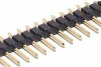
What is this cord called and how can I extend it?

4

1

I built a server recently, and the only hitch was that one of the cords running from my case to the motherboard was only just long enough. It is under strain, pulling at the connection point and pressing down heavily on my RAM chips, as you can see in these photos:
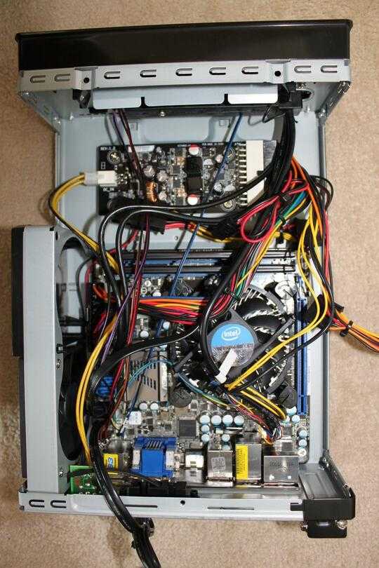
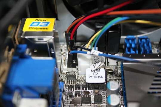
enter image description here enter image description here

I'm guessing I could just stick in an extension and run the cord around the edge of the box. But the problem is I don't know what these cords are called, or whether it's even possible to buy an extension. The alternative is to wire one myself, but I'd prefer to just buy an extension if possible.

Does anyone know whether such a thing exists and, if so, what they're called?
Kent Boogaart

Posted 2011-09-18T10:19:20.333

Reputation: 469

i'm having a little trouble telling WHICH cord specifically.. the blue one? – Journeyman Geek – 2011-09-18T10:30:35.357

The blue and black - two wires, but one cord. – Kent Boogaart – 2011-09-18T10:32:33.077

Maybe a little more information, what is it running from? What does the cable tag say "PO?" what is the label on the board by the port? – N4TKD – 2011-09-18T10:36:25.600

It looks REMARKABLY like a standard pin header - a 0.1" inch one, most likely, and the words look like 'power'. If its a power switch, it should be simple. Could you take a photo of the label, the area around the headers they plug into (or the letters there) and the wires in question to be sure? if its a power header, cannibalising from an old system should be simple – Journeyman Geek – 2011-09-18T10:41:02.877

Yeah, it's POWER+ and POWER-. Incidentally, I tried the machine without connecting these first in the hopes that they weren't that important (eg. just for an LED), but it failed to start up. – Kent Boogaart – 2011-09-18T10:44:47.883

power button leads. As long as they're bridged, they should boot. – Journeyman Geek – 2011-09-18T11:04:44.490

Answers

3

This is how I would do it - it's a soldering job:

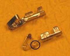
  • Look at the black connector housings on the end of the cable and they should have a slot through which a metal tab (circled in pic below) can be seen - this is the locking tab for the metal connector inside the plastic housing. By pushing the tab back down with a small jewellers' screwdriver, you can pull out the metal connector - careful as they are quite thin.

Crimp connector

  • Next, carefully cut the connectors off the wires. Usually, the connectors are crimped onto the wire.

  • Carefully solder a pair of new wire tails over the top of the crimp area on the connector. You could use some 'spare' wires from previous motherboard builds or perhaps strip the cores out of an unneeded network or other cable. Sometimes it's necessary to cut off the top off the connector where the original wire's insulation was crimped down for strain relief in order that the new wire sits flush when soldered.

  • Using a fine blade or small screwdriver, gently raise the metal locking tab you initially pushed down - about 0.5-1mm - and slide the metal connectors back into the plastic housings and confirm they lock back in.

  • Slide about 2cm of heatshrink sleeving over the tails - or skip this and use electrical tape over the joints later.

  • Strip both sets of wires about 2mm and solder the tails to the existing wires.

  • Slide the heatshrink sleeving into place and shrink it - or use the electrical tape - to cover the solder joints.

Linker3000

Posted 2011-09-18T10:19:20.333

Reputation: 25 670

This sounds like my best option - many thanks. – Kent Boogaart – 2011-09-19T17:49:26.057

1

From the hints in the comments on the question and the pic, looks to me like that is the wires from the power button.

Basically, when the power button is pressed, the two wires are connected, current flows momentarily, and that is the signal for the BIOS to turn the computer on.

I don't think you'll find it easy to find an extension cable for such a wire, but you could try wiring one up yourself. I've had to do something similar myself (extending wires for a fan lead), and I just snipped the cable, stripped the wires, and twisted in some more wire I found out of some old computers, and used electrical tape to seal the connections. If you're unsure about messing around with that sort of stuff though, I'd suggest going to an electrician, or TV/Radio repair shop or something like that. They'd likely be able to do it for reasonably cheap.

camster342

Posted 2011-09-18T10:19:20.333

Reputation: 1 691

If you want to completely confirm that it is the power button wires (and you don't have the motherboard manual), you could try shorting the two pins to see if the computer turns on. This way is a bit risky though, and I take no responsibility for damage caused blah blah blah... :). That said, I've had PCs with broken power buttons that I've had to turn on by shorting those pins with a butter knife... – camster342 – 2011-09-18T11:04:45.627

2If you want to build an extention cord - the pins are standard - 0.1inch, and you can get male and female headers - its a quick solder job. As long as those two pins are bridged momentarily, the system goes on or off. I've bridged the two pins with a coin for testing without a case. – Journeyman Geek – 2011-09-18T11:09:06.107

1

A company like Show me cables may be able to help you with this. But it seems to be the power button which uses a low voltage and a snip and splice in more wire of the same gauge wire should work just fine.

N4TKD

Posted 2011-09-18T10:19:20.333

Reputation: 979

1

I think these are standard pin/connector arrays with 1/10", ie. 2.54mm spacing. Go to your local electronics store and ask for pin array and the female counterpart with 100mil (imperial) or 2.54mm spacing. You need them to solder the cable yourself, but if ready-made exist, I have no idea where to get them.

This is an example of the pin header male part:

http://www.partco.biz/verkkokauppa/images/tuotekuvat/p/pr1x40u_zuum-medium.jpg

http://www.partco.biz/verkkokauppa/product_info.php?products_id=8340&language=en

In this case the array is 40 pins long, but it can be cut to desired length with pliers (see the grooves between every pin).

Zds

Posted 2011-09-18T10:19:20.333

Reputation: 2 209

You might be able to find some long socket to socket header leads ('PCB patch leads') and use them as extension leads onto the exiting wires with a couple of straight pin headers, but I can't think of a supplier who has these off the shelf. – Linker3000 – 2011-09-18T12:01:23.700

-2

pull them out.. run the computer. It's probably not a fan but make sure fans come on just to be sure. But test power button and reset buttons 'cos it could be one of those.

Those one pin things that go to the front of the case, could be the power button, HDD LED(LED on the front of the case showing HDD activity), or reset button..

you might even see what it is by running it when it's out and running it when it's in like if it's an LED.

or you could fish out the motherboard manual and it'd have a picture with clear markings, particularly useful if the motherboard markings aren't very readable.

To extend, well, if you have another box you could cut some similar sized ones and strip them and tie them together. When you cut them and strip the ends it's just copper wires you can twist together. or an electronics store has wires like that on a reel.

barlop

Posted 2011-09-18T10:19:20.333

Reputation: 18 677

could anybody explain with some reason, why my comment has been downvoted? if it's the copper wire, you can get electrical tape so they're not exposed. – barlop – 2011-09-18T11:43:55.623

1I marked down as the method of joining wasn't explained in detail and tieing or just twisting together isn't very clear and may result in very poor joints. – Linker3000 – 2011-09-18T11:54:29.060

@Linker3000 though your procedure including using a soldering iron would be a bit complex for somebody that wouldn't know how to twist wires sufficiently so they don't come apart. I do know how to twist wires together, but even for me, terms like "the crimp area on the connector" sound a little unfamiliar to me, and your procedure looks quite complex(to follow off the top of my head), i've never even seen those little gold things you have a picture of.I think anybody that can follow your procedure(I probably could),wouldn't be scratching their head about how to strip and twist wires together – barlop – 2011-09-18T21:19:51.060

@barlop (I wasn't a downvoter but...) you've suggested to pull them out and test, but he had already said in the comments that the computer doesn't work when he pulls the wires off of the particular pins he is talking about... but in general otherwise, it's okay information... – camster342 – 2011-09-19T05:16:04.983