Is this network setup possible/valid?

2

I previously asked this question on network engineering but my question was put on hold there and I was advised to try it on superuser, so here I am.

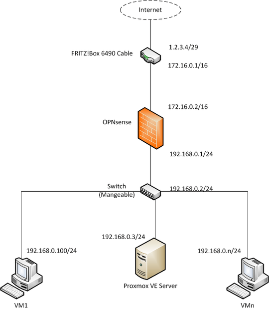
I am planning a little network for a business visualized in the following figure:

enter image description here

To provide some more information, the IP 1.2.3.4/29 is a static external address given by our ISP. A FRITZ!Box and an OPNsense route into/through their 172.16.0.0/16 network. The OPNsense has another 192.168.0.0/24 network on its LAN interface. In this network a manageable switch and a server hosting VMs reside. The VMs are provided with IP adresses via the hypervisor of the server (Proxmox VE).

My question is simple, do you think this setup is valid? Btw. the goal of this is to be able to reach the VMs from the Internet via a remote desktop solution.

Thank you for your valuable comments/answers.

Kind regards, David

UPDATE: I changed the picture and description to better fit a correct solution and your contributions.
David Artmann

Posted 2018-08-08T20:19:38.123

Reputation: 123

2The updated diagram looks good. – user1686 – 2018-08-09T07:15:18.313

@grawity thanks for you comment. Where has your answer gone? I wanted to acknowledge it as correct answer. – David Artmann – 2018-08-09T07:21:20.797

To make your scheme absolutely correct you can divide your switch by two parts. First (existing) have no address at all and have a name 'Switch, switching part'. Second (connected to the first by a line like server or vm) have address (192.168.0.2/24) and a name 'Switch, manage part'. And draw a circle around both parts for to show that it is one device. – Akina – 2018-08-09T08:26:51.073

The server hosts the virtual machines as it has a hypervisor (Proxmox VE) installed. More specific, the server owns two physical NICs (I ommitted one of them in the figure because I want the Switch to LAG them logically into one). What subnets are used for both NICs and all VMs? Show them/ And mark interfaces where NAT is used additionally. This info may alter some recommendations - up to make your scheme non-correct. – Akina – 2018-08-10T06:20:00.053

Answers

0

1) Each connection (a line in your picture) is for connecting 2 devices with different IP addresses from the same subnet.

2) Each device owning 2 or more interfaces (all except VMs) has a separate IP address for each interface from a different subnet unique for the whole scheme.

So your scheme may looks like (as I understand your server have 4 separate NICs - one WAN and 3 attached to VMs by separate patch-cords):

                   Internet
                       |
                   1.2.3.4
                    Router
                 172.16.0.1/24
                       |
                 172.16.0.2/24
                   firewall
                 192.168.255.1/24
                       |
                    switch (192.168.255.3/24)
                       |
                 192.168.255.2/24
                     WAN NIC
                     Server
     NIC1              NIC2              NIC3
192.168.1.1/24    192.168.2.1/24    192.168.3.1/24
      |                 |                 |
192.168.1.2/24    192.168.2.2/24    192.168.3.2/24
     VM1               VM2               VM3

A switch has no own IP address in routing scheme. Its IP is only used for management.

Additionally: router and firewall should have the routes to 192.168.0.0/22 via 172.16.0.2 and 192.168.255.2 respectively.

Update: If your modem is a simple interface converter, and not a router, it will have no address, and 1.2.3.4 will be the address of the firewall's WAN interface. In that case the firewall must operate as a NAT-router, not as a simple router.

Akina

Posted 2018-08-08T20:19:38.123

Reputation: 2 991

The server hosts the virtual machines as it has a hypervisor (Proxmox VE) installed. More specific, the server owns two physical NICs (I ommitted one of them in the figure because I want the Switch to LAG them logically into one). – David Artmann – 2018-08-10T06:00:42.970

@DavidArtmann It does not matter. Except additional subnets not shown on scheme (and additional routes you need to add on some nodes). PS. '/22' mask is not an error. – Akina – 2018-08-10T06:06:11.043

Yeah, I just wanted to inform about how the setup is meant to work. Regarding the /22, I did this to make your visualization fit more to my figure. And btw. thanks for your hint regarding the two routes. – David Artmann – 2018-08-10T06:10:55.837

/22 mask allows to create 1 route to subnets 192.168.0.0/24, 192.168.1.0/24, 192.168.2.0/24 and 192.168.3.0/24 instead of 4 separate routes on my scheme. It's a common practice to join subnets in routing table. – Akina – 2018-08-10T06:16:25.317

Ok, I understand. But these networks are simply not existing in my setup ;) Anyway, then my edit of your subnet needs to be rewinded. – David Artmann – 2018-08-10T06:18:50.987

Yes. But my answer deals with initial scheme. – Akina – 2018-08-10T06:20:56.340

Also in the initial scheme these networks did not exists, didn't they? – David Artmann – 2018-08-10T06:23:12.403

Your initial scheme contained 3 separate server-vm links with separate subnets needed. So I draw separate 3 NICs and subnets in my scheme. – Akina – 2018-08-10T06:46:27.973

Yes, you're right, my initial figure was unclear regarding the links of the VMs. Sorry for that. – David Artmann – 2018-08-10T06:58:20.250