I've been playing with packet tracer and trying to fully grasp ip routing. So far I'm doing ok i think.
Why am i able to ping r3 from pc1 (route working correctly as it should) vice-versa but cant ping r3 from r1.
I've been playing with packet tracer and trying to fully grasp ip routing. So far I'm doing ok i think.
Why am i able to ping r3 from pc1 (route working correctly as it should) vice-versa but cant ping r3 from r1.
I guess R3 don't know the "network 1" (subnet between R1 and R2). When R1 sends the icmp echo request (ping) it will use the IP address of the interface that the packet uses to exit the router as a source, in this case, the IP of the interface connected to "network 1".
from R1, try extended ping using the IP of the interface connected to Network2.
here you can find details about extended ping: https://www.cisco.com/c/en/us/support/docs/ip/routing-information-protocol-rip/13730-ext-ping-trace.html
If the issue persists, could you please share the configuration of R1, R2, and R3?
Regards,
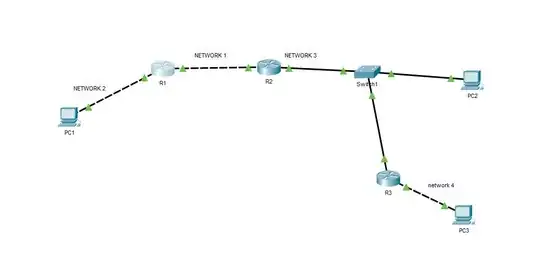
So, I've redrawn your topology.

Let's assume on the PC1 the network interface has name PC1-N1-IF with assigned address PC1-N1-IP. On the R1 router the network interface connected to the NTWRK1 has name R1-N1-IF with address R1-N1-IP. And so on.
After assignment of addresses to interfaces the routing tables on the devices will looks like:
PC1:
directly-connected NTWRK1, iface <PC1-N1-IF>R1:
directly-connected NTWRK1, iface <R1-N1-IF>directly-connected NTWRK2, iface <R1-N2-IF>R2:
directly-connected NTWRK2, iface <R2-N2-IF>directly-connected NTWRK3, iface <R2-N3-IF>R3:
directly-connected NTWRK3, iface <R3-N3-IF>directly-connected NTWRK4, iface <R3-N4-IF>PC2:
directly-connected NTWRK3, iface <PC2-N3-IF>PC3:
directly-connected NTWRK4, iface <PC3-N2-IF>To get the full connectivity in your topology you need:
PC1:
R1: ip route 0.0.0.0 0.0.0.0 <R1-N1-IP>R1:
NTWRK3 via R2: ip route <NTWRK3> <R2-N2-IP>NTWRK4 via R2: ip route <NTWRK4> <R2-N2-IP>R2:
NTWRK1 via R1: ip route <NTWRK1> <R1-N2-IP>NTWRK4 via R3: ip route <NTWRK4> <R3-N3-IP>PC2:
NTWRK1 via R2: ip route <NTWRK1> <R2-N3-IP>NTWRK2 via R2: ip route <NTWRK2> <R2-N3-IP>NTWRK4 via R3: ip route <NTWRK4> <R3-N3-IP>R3:
NTWRK1 via R2: ip route <NTWRK1> <R2-N3-IP>NTWRK2 via R2: ip route <NTWRK2> <R2-N3-IP>PC3:
R3: ip route 0.0.0.0 0.0.0.0 <R3-N4-IP>We use simplest configuration without recursive routes and address aggregation. Try to determine how the routing table will look after adding the routes on some device.
Additional readings: