Your network is working as expected. Lets draw it:
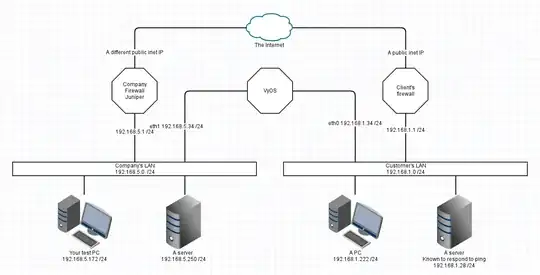
This is a simplification I'm sure, but has enough information here to show the problem and the various fixes (and their drawbacks)
Assumptions
- Each device uses the LAN's firewall IP as its default gateway.
- DNS is not important
- All netmasks are /24 in this example
- The two LAN topologies were given as being VLANs. I've left that out for now and we're representing each VLAN as a separate physical LAN.
- The fixes assume you can administer the rules on all three routers/firewalls
For those following the OSI stack, this is all IP and is at layer 3.
1. Directly Connected Networks
Your PC has a packet to send to an IP. First thing it does is checks if Destination IP is in the same local IP network. If both the SRC and DST addresses share the same Network (being the bit of the IP that remains after the subnet mask is applied) then the OS sents the packet out an ethernet interface. The OS labels the outbound packet with the source IP of the interface on which it exits.
Your test PC sends packets with a SRC IP of 192.168.5.172 Destination is 192.168.5.250 Your netmask is /24 which is 255.255.255.0, leaving a network of 192.168.5.x Therefore your PC can send directly by putting the packet out the ethernet and the destination will receive it.
2. Default Gateways
A default gateway, default route, gateway, router of last resort, is the thing you send packets to when you don't have a better route to send them.
Here are the default routes in your network:
So if the destination IP is not local (directly connected) then TestPC knows to address the packet via the default gateway.
There is only one default gateway IP address for a device (handwave - yes I'm trying to keep it simple.)
(side comment) If the VyOS box has a default gateway set, it is probably via your office Juniper. That's nice for updates and stuff, but its not relevant to your environment. Its also totally reasonable for VyOS to not have any default gateway configured at all.
3. Specific Routes
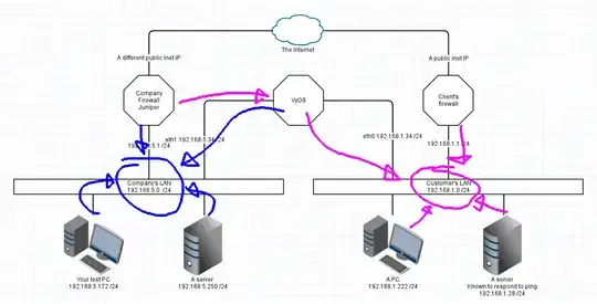
Your traceroute from the question indicates that the two office firewalls have specific knowledge of the other LAN.
So each firewall will have an additional route configured.
Your Company Juniper knows to "access 192.168.1.0/24 via 192.168.5.34"
Their firewall knows that "192.168.5.0 255.255.255.0 via 192.168.1.34" or similar. Pictorially that means:
4. Be one with the packet
So lets visualise this from the point of view of a packet.
a. TestPC pings google (I'm using ping because its stateless and easier than explaining a TCP connection like HTTP)
- Packet is to 8.8.8.8 This is not in 192.168.5.x so testPC throws it on the ethernet with a DST of 192.168.5.1
- Juniper receives a packet with SRC 192.168.5.172 and DST 8.8.8.8 It is configured to NAT and forward this packet. The SRC address is rewritten to the external Inet IP on the Juniper and thrown to the ISP. Juniper keeps track of this connection in a table in memory.
- Packet goes to google, and a reply comes back through ISP with a SRC of 8.8.8.8 and a DST of the Inet IP
- Juniper looks up its connection tracking table and finds that this is a reply on a connection started by TestPC. So it changes the DST to 192.168.5.172 and pushes this packet on the LAN interface (because that's the interface which is directly connected to 192.168.5.x
- TestPC hears a packet for its IP and grabs it off the wire (more handwaving here)
This as a picture:

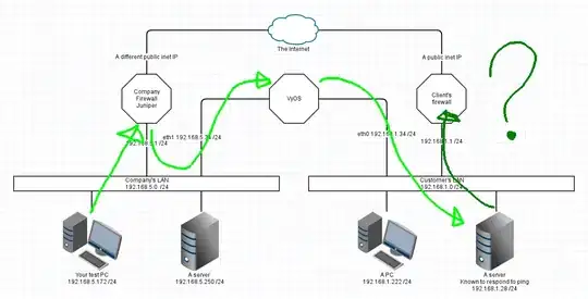
b. TestPC will now ping Customer's Server at 192.168.1.28
- As above, testPC does not have a direct connection to 192.168.1.x so it addresses the packet to its default gateway, the Juniper.
- Juniper is configured to forward packets, but it has a static route to 192.168.1.x via VyOS at 192.168.5.34 So instead of using NAT to change the destination to the ISPs gateway, the Juniper forwards the packet via VyOS.
- VyOS knows about two networks only. It sees a packet in one side for the other side and simply forwards it on the other interface
- CustyServer sees the packet and receives it. Halfway!
- CustyServer sends a reply to 192.168.5.172 but that's not directly attached, so we go to the default gateway.
- The custy firewall has NO IDEA what to do with this packet, so it likely gets dropped, or may be forwarded to their ISP who then drops it.
- At this point its all over. Reply packet is lost, and TestPC will wait until timeout for the answer.
Here's that last as a picture:
How do we fix this? There are multiple different fixes.
1. Interconnect Network
This is the "proper" design, using a small interconnect network between your two firewalls, and doing away with the VyOS device. I've used 172.22.22.x/24 as an interconnect LAN. A /24 is quite large, but keeping this simple.
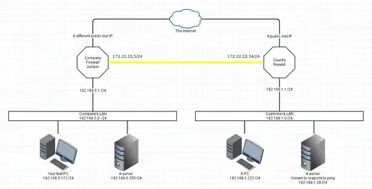
Positives
- Each firewall knows about all traffic and can be connection-tracked properly.
- One device at each company for firewall changes, not two places to check
- Each LAN device has the simplest setup possible.
Drawbacks
- Both firewall devices will require an additional ethernet interface, and an ethernet cable run between them.
2. Add a static route on the Customer's firewall
It seems to be missing. If you added the blue arrow from Customer Firewall to VyOS then it would work better.
3. Add a SOURCE NAT at the VyOS device
Someone famous once said "If your plan involves adding more layers of NAT then you don't understand the root problem" I don't really think this is a good idea.
If the VyOS device NATs all traffic between the two networks to its OWN IP in that LAN then reply traffic will not attempt to go to the default gateway.
Main downside is that you'll see all traffic coming from the VyOS IP, and you will have no idea who the real sender is. This makes forensics somewhat more difficult.
4. Static route all the things!
This is a terrible answer, but in some situations it might be appropriate.
If every LAN device had a routing table like this, then they'd all know how to talk to the custy LAN.
# ip ro ls
default via 192.168.5.1 dev eth0
192.168.1.0/24 via 192.168.5.34 dev eth0
192.168.5.0/24 dev eth0 proto kernel scope link src 192.168.5.173
Downside, this is a management nightmare. It might be workable if you have only a couple devices that never move, but adding them dynamically is messy.
Possible saves
- Active Directory can push out static routes with Group Policy. Won't help any device that isn't a domain-joined windows box. Printers, phones, APs, everything else misses out. That's all I know about that.
- Its possible to push a static route with DHCP, but most implementations ignore the offer. pfSense can do it, but windows10 ignored the option.
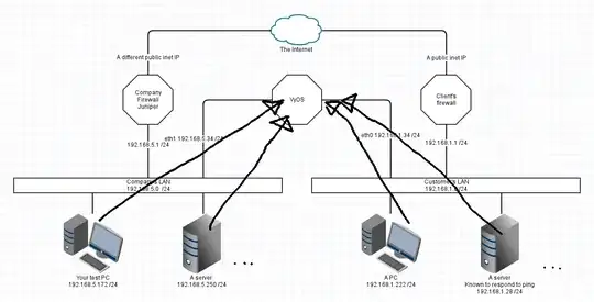
In summary
LAN Maps are awesome solutions for understanding your networking problem. Love them! I've used http://www.gliffy.com/ to create the background image for these illustrations.
KISS If a solution is tedious and complex, its probably the wrong solution.


