6

top number is transmitter bottom number is remote terminator

12345678
36145278

is this because I could be mixing T568A and T568B wiring? how do I know if my patch cord is A or B? Do I just look at the plug and match it up with the diagram on the back of the panel somehow?

plug wired patch panel

EDIT I read that 36145278 indicates a cross over cable, but I'm not trying to make a cross over. Where did I go wrong? I'm guessing the cable plug is T568A but I wired it to the panel using T568B. So I need to redo it as T568A. But in the future how do I know if I cable is A or B?

Cheers!

Max Hodges
  • 336
  • 2
  • 3
  • 15
  • 1
    why are you wiring one end to a patch block with the other end a rj45 male? – TheCleaner Apr 17 '13 at 18:45
  • the devices which connect to the patch panel might move around. so they connect with patch cords. but the switch on the other end of the patch panel is in. permanent location. so I can spare myself the effort of another patch panel by just connecting the cables to the switch. is anything terribly wrong with this idea? – Max Hodges Apr 17 '13 at 19:05
  • Not necessarily, just not what you typically see. – TheCleaner Apr 18 '13 at 12:58

6 Answers6

3

OK let me know if I'm wrong here but I think I figured it out.

Basically if one side of the plug starts with WHITE/ORANGE its T568B. If one side starts with WHITE/GREEN then its T568A.

If one end is T568A and the other is T568B then its a crossover.

Max Hodges
  • 336
  • 2
  • 3
  • 15
  • 2
    Crossover is obsolete and you should never make one for Gigabit or almost never for 100Mbps. Also, you need to untwist as little wire as possible. You've removed about two more twists than you should -- that allows the signals to interfere with each other where they're untwisted. – David Schwartz Apr 17 '13 at 17:46
  • thanks for the tips! I assume you think my answer here is on track? – Max Hodges Apr 17 '13 at 19:08
  • 1
    This answer misses the point. It talks as if the OP had a RJ45 connector on BOTH ends of the cable. *He doesn't*. Yes, one side is a RJ45 connector, so looking at the colour sequence tells you if *that* was T-568A or B; HOWEVER the other end was punched down into a patch panel, where the left-to-right sequence of wires doesn't tell you whether its A or B. Patch panels have their own, custom wiring sequences to maximize *ease of installation*. That's why the wires are grouped by colour in pairs on the panel, something that doesn't happen with either T-568A or T-568B. I'll post an answer. – Mr Ethernet Oct 27 '19 at 20:46
3

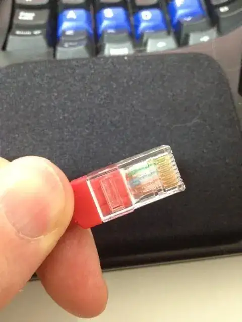
You can see that the rj45 plug has the blue wires in the center whereas on the patch panel they are on the side.

I know you explained why you have a patch panel on one end and a plug on the other, but it's generally not a good idea to mix both types. On both ends of the cable should be either a female or a male end.

The reason for this is that patch panels/blocks work best with solid core cables, but plugs are most effective with stranded cables. The ideal situation would be less than 90 meter of cable running from a patch panel near the router to a wall socket, and then connect the device to the wall socket with a patch cable with two plugs on both ends, shorter than 10 meter.

The problem with putting an rj45 plug on a solid core cable is that the little 'knifes' inside the plug don't cut into the wire as they would with stranded cable. They just sit on top of it, often giving you bad or even no connection at all.

  • There are multiple mistakes in this answer. "You can see that the rj45 plug has the blue wires in the center whereas on the patch panel they are on the side." The left-to-right colour sequence used on patch panels is neither T-568A nor T-568B. Patch panel wiring is in an order that maximizes ease of installation by keeping each of the coloured pairs together. Secondly, "blue is in the middle" is a flawed argument as blue is *always* "in the middle" (pins 4 + 5). Only the green and orange pairs cross over from A to B. See my answer for a full explanation. – Mr Ethernet Oct 27 '19 at 21:29
3

There is a lot of inaccurate and misleading information here. Even the accepted answer fails to understand exactly what happened at the punch-down block side of the cable.

I am posting a more accurate answer to help anyone else who may find themselves in a similar situation.

Let's review the OP's question again:

Is this because I could be mixing T-568A and T-568B wiring?

How do I know if my patch cord is A or B?

Do I just look at the plug and match it up with the diagram on the back of the panel somehow?

There are two parts to the question:

  • the RJ45 connector end of the cable.
  • the patch panel end of the cable.

RJ45 connector:

An Ethernet cable's Rj45 connector can easily be identified as following either the T-568A or T-568B wiring standard if the wires are in either of the following sequences:
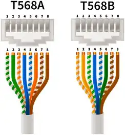
enter image description here

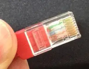
  • The OP's patch cable clearly had the green pair in pins 1 and 2.

  • We can see that the RJ45 connector was clearly wired using the T-568A standard:

enter image description here

So far, so good.

The second half of this question seems to be where people got confused.

Punch-down block:

  • The other end of the Ethernet cable did not go into another RJ45 connector but into a punch-down block.

  • A crucial detail here is that the wiring on a punch-down block does not follow the same left-to-right colour sequence as either a T-568A or T-568B RJ45 plug. People are assuming that the sequence is the same, despite the fact there is a label in the photo of the punch-down block that shows a very different colour sequence from both T-568A and T-568B.

  • The left-to-right wire positions on a punch-down block do not directly correspond to pins 1-8 in an RJ45 connector: the order is completely different.

  • Punch-down blocks keep the coloured pairs together for ease of installation. The actual sequence varies between manufacturers and models, just as it does with keystone jack wiring.

Here is an example of an answer that provided incorrect information by assuming that the left-to-right wire sequence represents pins 1-8, as it does in an RJ45 plug:

You can see that the rj45 plug has the blue wires in the center whereas on the patch panel they are on the side.

  1. The blue pair is always in exactly the same location, pins 4 + 5, regardless of whether a cable is terminated as A or B. So even if the sequence was the same at the patch panel, using the blue or brown pairs wouldn't allow you to differentiate between T-568A or T-568B as those pairs never change position anyway.

  2. The assumption that the wiring on a punch-down block should have the same colour sequence from left to right as it does on an RJ45 connector is a mistake as it fails to recognize that punch-down block manufacturers use a completely different colour sequence for ease of installation.

We can clearly see from this photo that connection #12 on the patch panel's punch-down block is wired according to the panel's wiring instructions for T-568B.
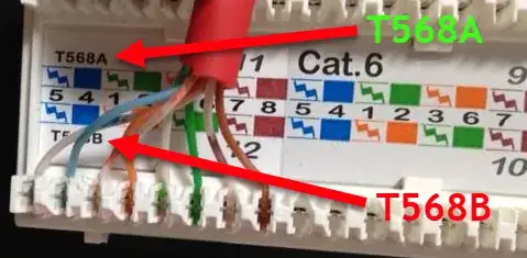
enter image description here

Conclusion:

  • The RJ45 connector was wired according to T-568A.
  • The patch panel was wired according to T-568B.
  • Therefore, as both ends used opposing wiring schemes, the resulting cable was effectively a crossover cable, hence the 36145278 result seen when the cable was checked using a continuity tester.

Solution:

The orange and green pairs should be released from the punch-down block and connected according to the wiring instructions for T-568A, as seen in the top half of the above photo.
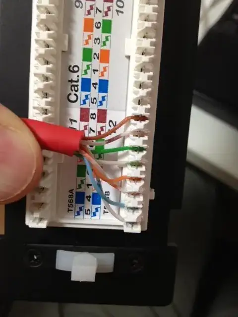
Mr Ethernet
  • 156
  • 4
  • The real answer is that it is highly unlikely that an inexperienced person can do this and get it to pass the Category-6 test suite with a real network tester. I have seen experienced installers struggle with Category-6 punchdowns, and something as simple as having the last twist be blue over blue-white, rather than blue-white on top can cause it to fail the test. – Ron Maupin Oct 27 '19 at 23:01
  • No. The "real answer" is that the OP punched down using T-568B instead of T-568A at the patch panel, as clearly shown in the last photo in my answer. It has nothing to do with Cat 6 cables specifically; the same thing would happen if it were a Cat 5e cable. This wasn't about failing the Cat 6 test with a subtle mistake. Half the wires were in the wrong positions altogether. – Mr Ethernet Oct 27 '19 at 23:04
  • The question asks about Category-6 cabling. Also, the 8P8C connectors on the cable are normally designed for stranded cable (patch cords), while punchdown blocks are normally designed for solid-core cable (horizontal cable), but trying to mix that will cause it to fail in the future. In any case, I would not bet my business on this installer, and I seriously doubt that a proper cable tester to test the category test suite was employed. – Ron Maupin Oct 27 '19 at 23:06
  • "The question asks about Category-6 cabling". Sure, the question *mentioned* the fact it's a Cat 6 cable but all the OP was trying to get at was why the continuity was showing that he had a crossover cable. He didn't know how relevant it was that it was a Cat 6 cable and, as it turned out, that wasn't important at all. Wiring the two ends of *any* category of Ethernet cable this way (5, 5e, 6, 6a or 7) would have given him a crossover cable. "...punchdown blocks are normally designed for solid-core cable (horizontal cable)". Agreed. I would never use stranded Ethernet in a punchdown block! – Mr Ethernet Oct 27 '19 at 23:20
  • 1
    Actually, Category-5 was de-registered last century, and Category-7 has never existed. The currently registered cable categories are 3, 5e, 6, 6a, and 8. Simple electrical continuity is not what counts in modern cabling. The _basic_ tests are listed in [this answer](https://networkengineering.stackexchange.com/a/42697/8499), and all must pass or the cable be corrected or reinstalled until it passes all the tests, and the installer provides a test report for each installed cable. That is the only way a business should be installing cable. – Ron Maupin Oct 27 '19 at 23:27
  • After all, [sf] requires reasonable business practices for questions here: "_Questions should demonstrate reasonable information technology management practices. Questions that relate to unsupported hardware or software platforms or unmaintained environments may not be suitable for Server Fault._" – Ron Maupin Oct 27 '19 at 23:29
  • "Category-7 has never existed." Interesting. I guess the Category 7 cables you see in certain stores, like this https://www.memoryexpress.com/Products/MX78558 is ratified but still not recognized by the TIA/EIA. – Mr Ethernet Oct 28 '19 at 02:22
  • 1
    ANSI/TIA/EIA specifiy the cable categories, and they have resolutely refused to specify any shielded cable category, until Category-8. What is often called Category-7 is really the ISO/IEC Class F. ISO/IEC specify cable classes, and ANSI/TIA/EIA specify cable categories. The recognized categories are clearly stated in the current version of _ANSI/TIA/EIA 568, Commercial Building Telecommunication Cabling Standard_ (costs money to get it), where it is explained that the only currently recognized cable categories are 3. 5e, 6, 6a, and 8. – Ron Maupin Oct 28 '19 at 02:27
  • The cable categories must each meet certain specifications, and only those listed in the ANSI/TIA/EIA standard have specification to meet. The standard explains that there are no specified parameters, even for older cabling standards, e.g. Category-5, which have been de-registered. How would you expect to test Category-7 cabling if there have never been any specifications for it? – Ron Maupin Oct 28 '19 at 02:36
  • 3, 5e, 6, 6a and 8. That's good to know. Thanks for explaining. – Mr Ethernet Oct 28 '19 at 03:26
  • Does it really matter nowadays when all devices has **Auto MDI-X**? – hans Mar 02 '21 at 22:11
2

Ok, Here's the solution and it's pretty easy actually, if you know....

So I'm not a Network expert but I knew the solution was easy. I was punching down on my patch panel and terminating on the other end with an rj45. I was doing 568B on both ends and it wasn't working. I was looking at the diagram on the patch panel and it wasn't either B or A, it just had all the colors paired up together. So after almost a week of fudging with it I finally figured out that the patch panel itself internally crosses the pairs so that it ends up being a B pattern. That makes it easier for when you're punching down hundreds of Ethernet cable. You just go along with the colors instead of trying to remember the correct pattern. Hope this helps cause it was the simple answer I was looking for... Terminate or punch down with 568B on one end and then just punch down according to the diagram on the patch panel. DONE!

Wolfman007
  • 21
  • 1
0

Yes, you are terminating T568A and then, testing T568B. Just flip your green and orange pairs.

In the T568A pinout, the pairs 1&2 (white & green), and 3&6 (white & orange) are opposite of what the pinouts in T568B are. In T568B, the pairs are 1&2 (white & orange), and 3&6 (white & green). Both T568A and T568B have the same pinouts for pairs 4&5 (blue & white), and 7&8 (white & brown). In ALL pinouts the white wire that is paired with its colored partner is called the "tip", and the colored wire in every pair is known as the "ring".

Whether you use a T568A or T568B patch cable will not matter as "electrons are colorblind"...as long as the pinouts on both ends are the same, either will work. Make sure to maintain your network standard (Cat.5e or Cat.6). If you use any Cat.5e items on a Cat.6 network, you will lower all your metrics to that Cat.5e standard. As long as your patch cable ends are pinned-out the same (straight through) to either the T568A or the T568B pinout, you will be okay.

A "crossover" patch cable is pinned-out to T568A at one end, and to T568B at the other end. They are (or were) typically used when cascading two or more network hubs or switches. The advent of "smart switches" has pretty much negated their use.

  • This answer isn't helpful as it talks as if both ends of the cable have RJ45 connectors. They don't. One end has an RJ45 connector but the other is punched down into a patch panel and it's *at the patch panel* where the accidental crossover occurs. This answer doesn't even acknowledge the existence of the patch panel! – Mr Ethernet Oct 27 '19 at 21:36
-2

I haven't done this in years, but I believe T568B to T568A is a crossover cable for 10/100BaseT connections and you will need to make a gigabyte crossover cable to go faster.

I found a reference link for you: http://en.wikipedia.org/wiki/Ethernet_crossover_cable#Crossover_cable_pinouts

  • 3
    There is no such thing as a gigabit crossover cable. Gigabit interfaces automatically cross over when needed. – Grant May 29 '14 at 02:40
  • Yet another answer that missed the point of this question. One end was RJ45 but the other went into a patch panel. There's no mention of which standard each end of the cable actually used, even though this is fairly obvious as all eight wires are clearly visible at both ends. – Mr Ethernet Oct 27 '19 at 21:40