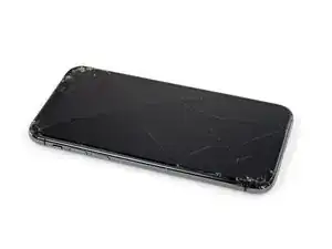
Introduction

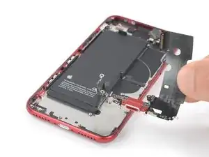
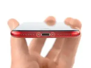
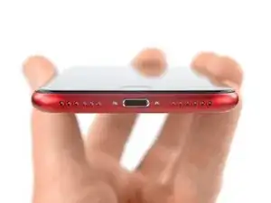
Use this guide to remove or replace the Lightning connector assembly for the iPhone SE 2022. This assembly includes the lower microphones, an antenna converter cable, and the Lightning connector. If you've tried cleaning the lightning port to no avail, replacing the Lightning connector can solve charging and connectivity issues.

This guide was performed on the A2783 (international) model.

If you do not replace the adhesive seals when reassembling, your device will function normally, but will most likely lose its water protection.

You’ll need replacement adhesive to reattach components when reassembling the device.

  1. bIdfBAAWZ4mdNkkf
    bIdfBAAWZ4mdNkkf
    su3kTSiDBJxiYd3L
    DvZ2E42UR62oGjYu
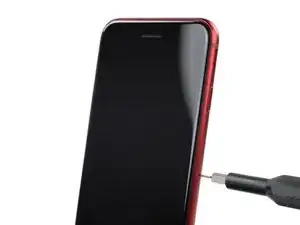
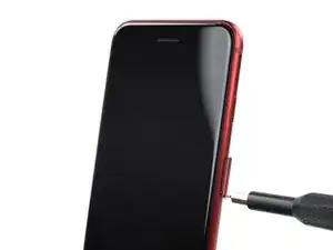
    • Insert a SIM card eject tool, a SIM eject bit, or a straightened paper clip into the hole on the SIM tray located at the right edge of the phone.

    • Press directly into the hole to eject the SIM card tray.

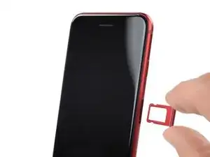
    • Remove the SIM card tray.

  2. GGG5DRQpWboQDlSA
    GGG5DRQpWboQDlSA
    XdXYeVMwpyc6vmec
    • Power off your phone before beginning disassembly.

    • Remove the two 3.4 mm P2 pentalobe screws on the bottom edge of the iPhone.

  3. 6UPwoloGBO4tmVoS
    6UPwoloGBO4tmVoS
    BmSYPJmOy6dbHipF
    3EOdQPAGOmiuhoKU
    • If inserted too far, an opening pick can damage your device. Follow this step to mark your pick and prevent damage.

    • Measure 3 mm from the tip and mark the opening pick with a permanent marker.

    • You can also mark the other corners of the pick with different measurements.

    • Alternatively, tape a coin to a pick 3 mm from the tip.

    Got to step 2 and realized the fix kit doesn't include an opening pick! Looks like a guitar pick, and I have those lying around. Is that expected? Looks like the pick is used in many steps below. There's a little blue crowbar that isn't mentioned in the instructions. Perhaps that replaces the opening pick?

    Sloan Looney -

    Hi! I can't see which guide you were using when writing this comment. Can you reply here with which guide and fix kit you used?

    Clay Eickemeyer -

    I see you posted this in Meta. I hope it's resolved soon! In the meantime, a guitar pick may work well enough for your repair.

    Clay Eickemeyer -

    what fix kit?

    Meow Purr -

    My fix kit didn't include an opening pick either

    WILLIAM HARRIS -

    Make sure you check inside the black boxes after emptying them. My pick was stuck inside one of the boxes.

    AndyF -

    My AliExpress refurbished screen came with a pick that has a coin-like circle that pops out, so no modification was necessary

    Gijs Leegwater -

  4. aTtMrSfAI3AgboW3
    aTtMrSfAI3AgboW3
    UJJk55l5C6R5uxoM
    g5TMyOYLfBAkAUxl
    • If your iPhone has a cracked screen, keep further breakage contained and prevent bodily harm during your repair by taping over the glass.

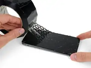
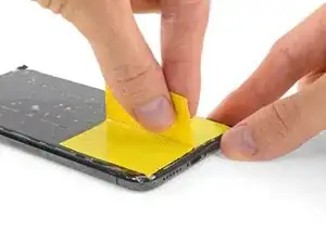
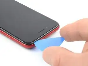
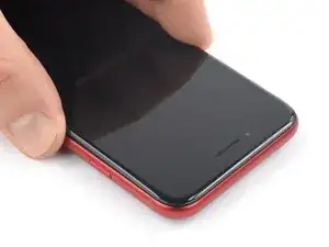
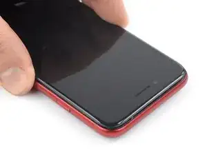
    • Lay overlapping strips of clear packing tape over the iPhone's screen until the whole face is covered.

    • Wear safety glasses to protect your eyes from any glass shaken free during the repair.

    • If you can't get the suction cup to stick in the next few steps, fold a strong piece of tape (such as duct tape) into a handle and lift the screen with that instead.

    • If all else fails, you can superglue the suction cup to the screen.

  5. fMGT6oUyUs3C5IZw
    fMGT6oUyUs3C5IZw
    kYiyMORPNxdhVgQo
    h2LZiCPUAAwIGWap
    • The next three steps demonstrate the Anti-Clamp, a tool we designed to make the opening procedure easier. If you aren't using the Anti-Clamp, skip down three steps for an alternate method.

    • For complete instructions on how to use the Anti-Clamp, check out this guide.

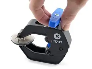
    • Pull the blue handle backwards to unlock the Anti-Clamp's arms.

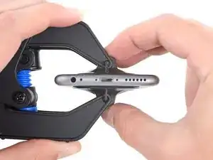
    • Slide the arms over either the left or right edge of your iPhone.

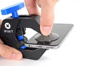
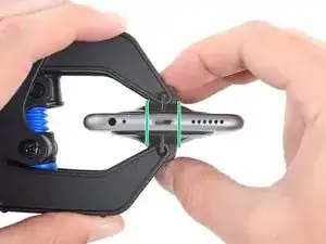
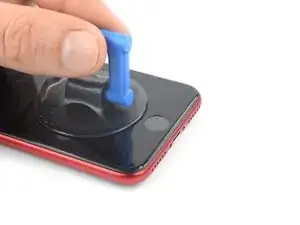
    • Position the suction cups near the bottom edge of the iPhone just above the home button—one on the front, and one on the back.

    • Squeeze the cups together to apply suction to the desired area.

    • If you find that the surface of your iPhone is too slippery for the Anti-Clamp to hold onto, you can use tape to create a grippier surface.

  6. MnrxDWxUGdAOaWBY
    MnrxDWxUGdAOaWBY
    uO2bXVCdISbjDRm1
    i2LYfjOvTbBZHDy2
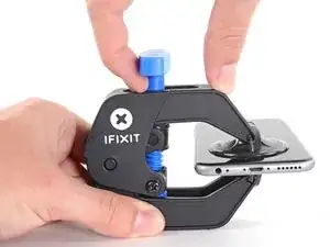
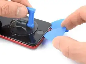
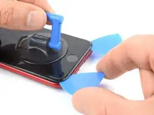
    • Pull the blue handle forwards to lock the arms.

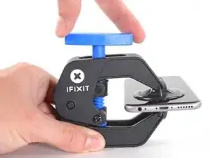
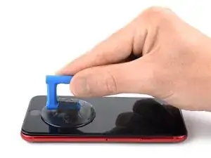
    • Turn the handle clockwise 360 degrees or until the cups start to stretch.

    • Make sure the suction cups remain aligned with each other. If they begin to slip out of alignment, loosen the suction cups slightly and realign the arms.

  7. OCLD65CXGpAcEt6M
    OCLD65CXGpAcEt6M
    DGuo4enQ1l3Bip4R
    yFrEYZM5sin332SA
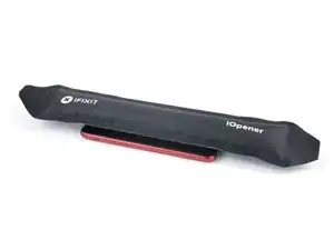
    • Heat an iOpener and thread it through the arms of the Anti-Clamp.

    • You can also use a hair dryer, heat gun, or hot plate—but extreme heat can damage the display and/or internal battery, so proceed with care.

    • Fold the iOpener so it lays on the bottom edge of the iPhone.

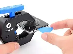
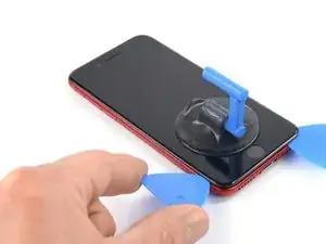
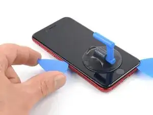
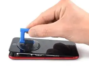
    • Wait one minute to give the adhesive a chance to release and present an opening gap.

    • Insert an opening pick under the screen's plastic bezel, not the screen itself.

    • If the Anti-Clamp doesn't create a sufficient gap, apply more heat to the area and rotate the handle a quarter turn.

    • Don't crank more than a quarter turn at a time, and wait one minute between turns. Let the Anti-Clamp and time do the work for you.

    • Skip the next two steps.

  8. dmLx3jBCnKiqER3P
    • If you're using a suction handle, follow the next two steps to loosen the rear glass.

    • Prepare an iOpener and apply it to the screen for at least two minutes to loosen the adhesive underneath.

    • A hair dryer, heat gun, or hot plate may also be used, but be careful not to overheat the phone—the display and internal battery are both susceptible to heat damage.

  9. rD6EXtETYK6W43BL
    rD6EXtETYK6W43BL
    hbLJnRXewjQryYWU
    2GmowdKF2n6OVMFt
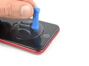
    • Secure a suction handle to the lower half of the front panel, as close to the home button as possible.

    • Lift the front panel with the suction handle to create a small gap between the front panel and the frame.

    • If you have trouble creating a gap, apply more heat to the bottom half of the screen to further soften the adhesive. Follow the iOpener instructions to avoid overheating.

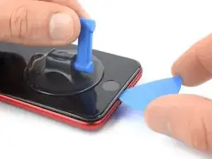
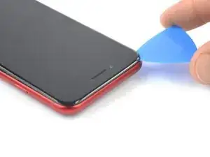
    • Insert an opening pick into the gap under the screen's plastic bezel.

  10. RlxbQliqSLEM2EaO
    RlxbQliqSLEM2EaO
    qTgGWqDlDtUKPxuD
    gA1LFGhlnRfFqQAL
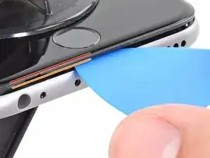
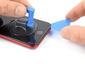
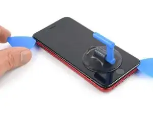
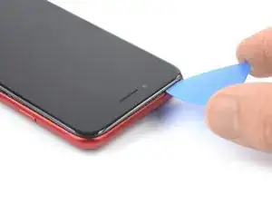
    • Slide the opening pick to the bottom right corner to slice the front panel adhesive.

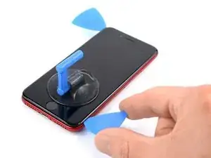
    • Insert a second opening pick at the bottom edge of your phone.

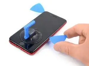
    • Slide the opening pick to the bottom left corner to slice the adhesive.

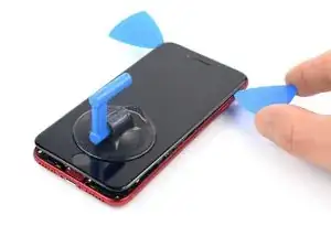
    • Leave the opening picks in place to prevent the adhesive from resealing.

  11. B22ufmmktismRyAX
    B22ufmmktismRyAX
    rU5fHWqNIZNBrniI
    iWpJiHFQUTS6d5nO
    • If the adhesive becomes hard to cut, it has most likely cooled down. Use your iOpener for two to three minutes to reheat it.

    • Slide the bottom left opening pick along the left edge of your phone to slice the adhesive.

    • Stop near the top left corner of the display.

    • Do not try to pry the top edge of the display away from the rear case, as it is held in place by plastic clips that may break.

  12. MdCdFmuXV3wpZgaQ
    MdCdFmuXV3wpZgaQ
    2oeM1KEYNYMbIopy
    VcrH5erBM4hnnRib
    • Slide the bottom right opening pick along the right edge of your phone to slice the adhesive.

    • Don't insert your pick more than 3 mm, as you may damage internal components.

    • Stop near the top right corner of the display.

  13. PVrRTalFwRJjLyMl
    PVrRTalFwRJjLyMl
    TuKLCySrOykReABT
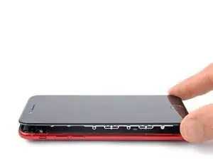
    • Remove the opening picks.

    • Gently pull up on the suction handle to lift up the bottom edge of the display.

    • Do not raise the display more than 15º or you'll risk straining or tearing the ribbon cables connecting the display.

    • Remove the suction handle.

  14. PaPQfMVnk14TFVyS
    PaPQfMVnk14TFVyS
    SHc23yyo2EcbXen4
    wXT3eJM6gpT5YsUh
    • Slide an opening pick underneath the top left corner of the display.

    • Slide the opening pick around the top left corner and along the top edge of the phone to slice the remaining adhesive.

  15. xWICR4vuLA1aP5Y3
    xWICR4vuLA1aP5Y3
    hTkaOdOaqoID5WZn
    • Slide the display assembly slightly down in direction of the charging port to disengage the clips holding it to the rear case.

  16. y32q2dWXG4cVWeOT
    y32q2dWXG4cVWeOT
    GQQr6a6WbdHTj2C2
    E3XlASBtSJ2JIose
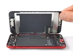
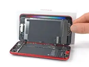
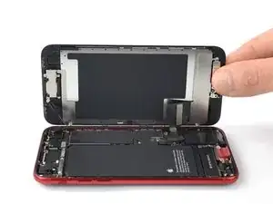
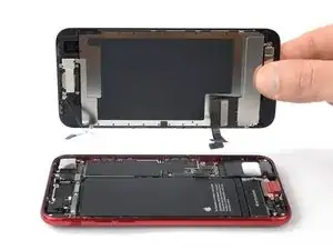
    • Open the phone by swinging the display up from the left side, like the back cover of a book.

    • Don't try to fully separate the display from the phone assembly yet, as several fragile ribbon cables still connect it to the logic board.

    • Lean the display against something to keep it propped up while you're working on the phone.

  17. 5HQFUu6AmYN4OlAy
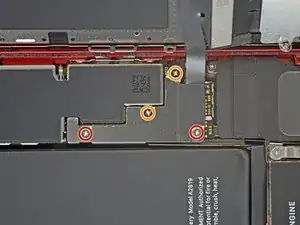
    • Remove the four Phillips screws securing the lower display cable bracket:

    • Two 1.2 mm-long screws

    • Two 2.8 mm-long screws

    • Throughout this guide, keep careful track of your screws so that each one goes back where it came from during reassembly. Installing a screw in the wrong place can cause permanent damage.

  18. DIQ3ZVFc1XcHUEaY
    DIQ3ZVFc1XcHUEaY
    ICtMmUpcMdqA3axd
    • Use a pair of tweezers to carefully remove the lower display cable bracket.

  19. kadZDtevxOASDjj4
    kadZDtevxOASDjj4
    cTPyu5mJSQSuXbkU
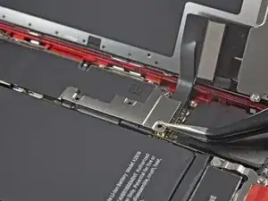
    • Use the pointed end of a spudger to disconnect the battery by prying the connector straight up from its socket.

  20. vt1FtSsZUNXsVx2p
    vt1FtSsZUNXsVx2p
    yYecSXPv2aWnOdbx
    tITbAT1tChsuHJmk
    • The display and digitizer cables run on top of each other. To avoid cable damage always start by disconnecting the upper cable first and never try to disconnect both at the same time.

    • Use the pointed end of a spudger to disconnect the bottom two display cables by prying the connectors straight up from their sockets.

    • To re-attach press connectors like this, press down on one side until it clicks into place, then repeat on the other side. Do not press down on the middle. If the connector is even slightly misaligned, the connector can bend, causing permanent damage.

  21. 4YS3lZFhlKE6BVAT
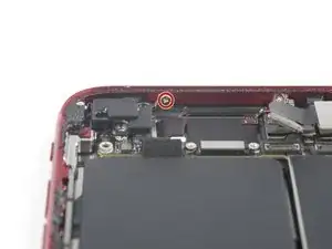
    • Use a Phillips screwdriver to remove the three 1.2 mm-long screws securing the front sensor assembly bracket.

  22. EufAVl6SybJmXmB2
    EufAVl6SybJmXmB2
    DU5xdDZEyHDIEj3o
    • Use a pair of tweezers to carefully remove the front sensor assembly bracket.

  23. 5qNVlyQAUtcEY1f2
    5qNVlyQAUtcEY1f2
    m2upMd2vsQhuyqWx
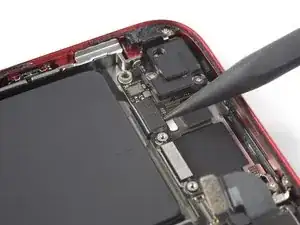
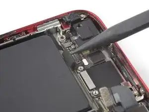
    • Use the pointed end of a spudger to disconnect the front sensor assembly by prying the connector straight up from its socket.

  24. eQJL2ptVADQiNBuA
    eQJL2ptVADQiNBuA
    r3PRyPkBMrFAOj5Z
    • Remove the display assembly.

  25. SgdkWKLfkVGkgeBW
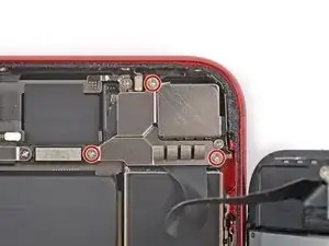
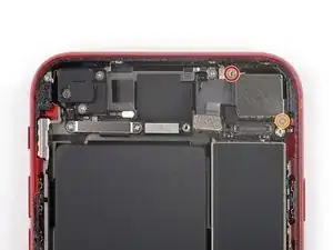
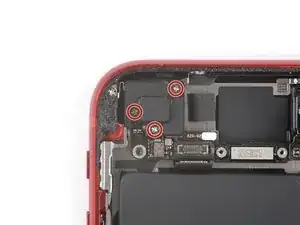
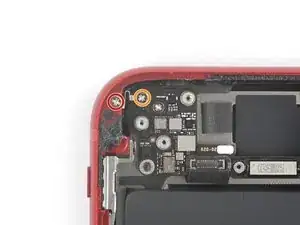
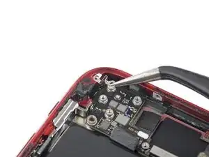
    • Unfasten the three screws securing the Lighting connector bracket:

    • One 1.2 mm-long Y000 screw

    • One 2.7 mm-long Phillips screw

    • One 2.9 mm-long Phillips screws

  26. tTQdhIEESU5ZSu1u
    tTQdhIEESU5ZSu1u
    hs6nmCv2MJyqdXWp
    • Use a pair of tweezers to remove the Lightning connector bracket.

  27. BJZdnn3BXwlWRIFM
    BJZdnn3BXwlWRIFM
    eU1JAENALNWPCQI1
    hZONNdIBpR5wmfPl
    • Carefully slide an opening pick between the antenna flex cable and the top of the speaker.

    • This portion of the flex cable is lightly adhered to the speaker. If you're struggling to separate the cable from the speaker, apply a little heat from an iOpener or hair dryer to soften the adhesive. This will make it easier to separate the flex cable safely.

  28. l6fDKCQHqTrKmIZJ
    l6fDKCQHqTrKmIZJ
    sGXa6q5m3VR4wfYB
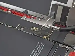
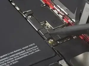
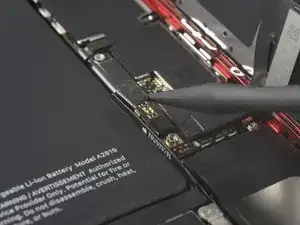
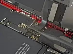
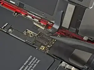
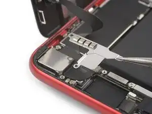
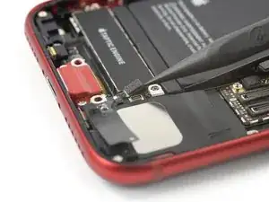
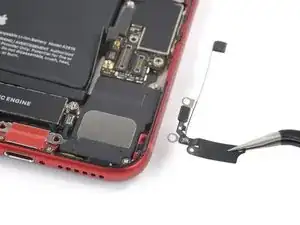
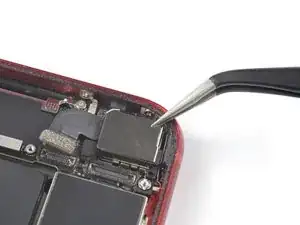
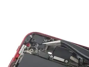
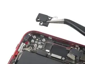
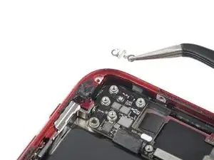
    • Use the pointed end of a spudger to disconnect the Wi-Fi diversity antenna by prying its connector straight up from its socket.

    • The socket of this connector sits loosely between the speaker and the Taptic Engine and it's a bit fiddly to disconnect the cable. To make the disconnection easier, you can use an opening pick to hold down the connector socket during this procedure.

    • Reconnecting this cable can be tricky. Make it easier by using tweezers to hold the flex cable so the connector aligns with its socket. Then, gently press straight down on the connector with the flat of your spudger until it clicks into place.

  29. m2kEnpSokusF64nJ
    m2kEnpSokusF64nJ
    dR6pSZDHGiMPhXgo
    • Use the pointed end of a spudger to disconnect the Wi-Fi diversity antenna from the logic board by prying the connector straight up from its socket.

  30. fCeVWM3wCv2fCpD6
    fCeVWM3wCv2fCpD6
    GLQVhADNADckhNGp
    • Use a pair of tweezers to remove the Wi-Fi diversity antenna.

  31. OC6uLbpYmYy3hnYM
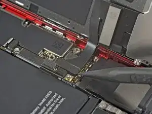
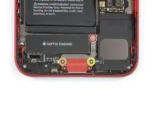
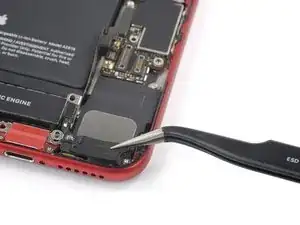
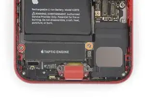
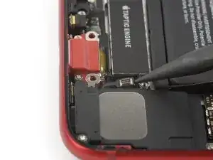
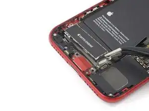
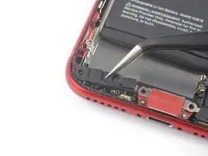
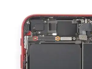
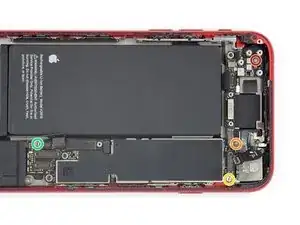
    • Remove the two screws securing the Taptic Engine:

    • One 2.1 mm Phillips screw

    • One 2.1 mm standoff screw

    • Standoff screws are best removed using a standoff screwdriver or bit.

    • In a pinch, a small flathead screwdriver will do the job—but use extra caution to ensure it doesn't slip and damage surrounding components.

  32. YoTZWcplD2WHjErl
    YoTZWcplD2WHjErl
    FnypRbOXJFWTJjhk
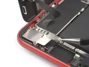
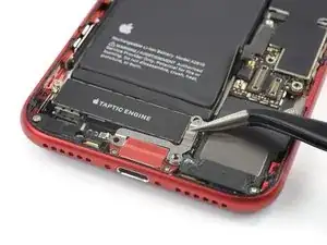
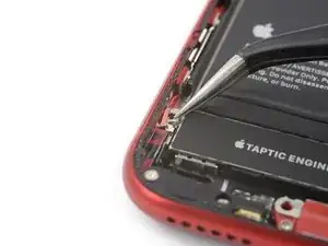
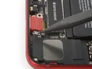
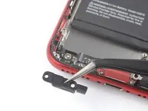
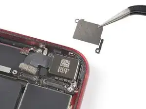
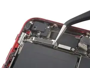
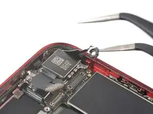
    • Use a pair of tweezers to remove the grounding bracket at the left edge of the Taptic Engine.

  33. H3GtiMuCDKUrVTKo
    H3GtiMuCDKUrVTKo
    dpvCdTpfYDRZyhHl
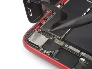
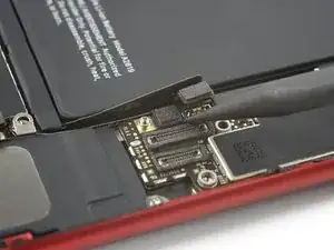
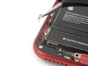
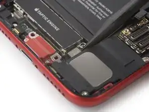
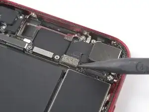
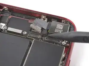
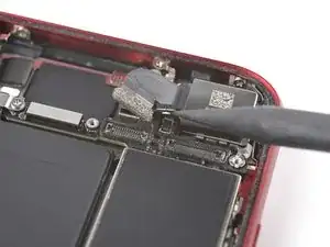
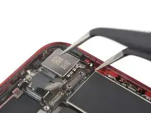
    • Use the pointed end of your spudger to pry the antenna cable socket up and away from the Taptic Engine connector below.

  34. VSN6oFxncHHnnJUY
    VSN6oFxncHHnnJUY
    XJruHiPiHAEQJbFK
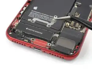
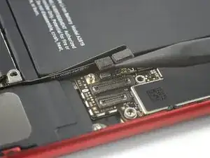
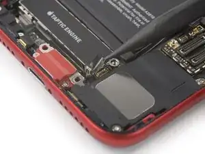
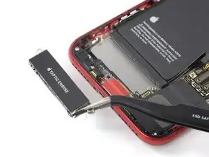
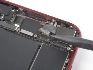
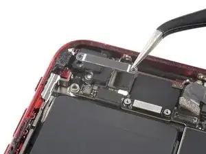
    • Use the pointed end of a spudger to disconnect the Taptic Engine by prying the connector straight up from its socket.

  35. KQNJhSGLUpVrWmX2
    KQNJhSGLUpVrWmX2
    s6eUyUulCE2uFuOC
    • Use a pair of tweezers to carefully remove the Taptic Engine.

  36. pDKcRHrwUnGeLOUs
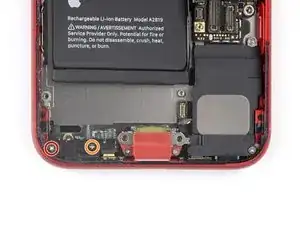
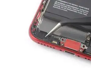
    • Remove the two screws securing the barometric vent:

    • One 1.9 mm-long Phillips screw

    • One 1.7 mm-long Phillips screw

  37. GdXZH2kSyYvLvGvW
    GdXZH2kSyYvLvGvW
    Za4PNCJLhrZ1OwjT
    BjwdMfmAspLY3NRJ
    • Use a pair of tweezers to remove the barometric vent.

    • The barometric vent is lightly adhered to the rear case. If you're struggling to separate the vent from the case, apply a little heat from an iOpener or hair dryer to soften the adhesive. This will make it easier to separate the barometric vent safely.

  38. Y5moI4jf1NXQKKNE
    Y5moI4jf1NXQKKNE
    62JCDpliSsYOj2Be
    • Use the pointed end of a spudger to disconnect the rear camera by prying the connector straight up from its socket.

  39. u1DdOKKeCP4nVHYN
    • Remove the two screws securing the rear-facing camera bracket:

    • One 3.0 mm-long standoff screw

    • Standoff screws are best removed using a standoff screwdriver or bit.

    • In a pinch, a small flathead screwdriver will do the job—but use extra caution to ensure it doesn't slip and damage surrounding components.

    • One 3.1 mm-long Phillips screw

  40. POtHIj6blbvaROOL
    POtHIj6blbvaROOL
    hvJwGJcWyjCEY5fX
    • Use a pair of tweezers to remove the rear camera bracket.

  41. ZexPLJSWU2LXOb5C
    ZexPLJSWU2LXOb5C
    xFHAe5cFlFGxTxTI
    • Use the pointed end of a spudger to disconnect the flash by prying the connector straight up from its socket.

  42. yyccMrPSAWv4fXmE
    • Remove the two screws securing the upper cable bracket:

    • One 2.8 mm-long Phillips screw

    • One 1.2 mm-long Phillips screw

  43. npOZHdyOU3D64Bi6
    npOZHdyOU3D64Bi6
    NdAW2KjUsHbjmArU
    • Use a pair of tweezers to remove the upper cable bracket.

  44. YHLDCyAxaWMLaViM
    YHLDCyAxaWMLaViM
    UGmoEoNVqIaciXRg
    • Use the pointed end of a spudger to disconnect the upper flex cable by prying the connector straight up from its socket.

  45. Iq5vdMqCciImVXel
    • Unfasten the three 1.2 mm-long Phillips screws securing the top left antenna component.

    • Don't try to remove the antenna component yet. There's a fourth screw securing it to the rear case.

  46. XQxEO3jY1XrjZsAF
    • Unfasten the 1.4 mm-long Phillips screw securing the antenna component to the top edge of the rear case.

  47. NgdcCSkwYWQ1cBs4
    NgdcCSkwYWQ1cBs4
    husrB3HompRuYPGC
    • Use a pair of tweezers to remove the top left antenna component.

  48. BUtw2VFF4136V3eS
    • Unfasten the two screws securing the top left grounding bracket:

    • One 1.5 mm-long Phillips screw

    • One 1.2 mm-long Phillips screw

  49. NMFilBSgDHSH5IXc
    NMFilBSgDHSH5IXc
    jrQK1DseEISYQhKJ
    • Use a pair of tweezers to remove the top left grounding bracket.

  50. MRsd6MWWUMgH3dMC
    • Unfasten the four screws securing the logic board:

    • One 1.7 mm-long Phillips screw

    • One partially threaded 1.7 mm-long Phillips screw

    • This screw is covered by protective foam surrounding the rear camera connector. Use a pair of tweezers to peel just enough foam off to unfasten the screw.

    • One 2.5 mm-long standoff screw

    • One 2.2 mm-long standoff screw

  51. nDEV3MPSSJfnXvWF
    nDEV3MPSSJfnXvWF
    GdPBgj1jjGG1Zc1v
    • Use a pair of tweezers to carefully pry up the logic board grounding bracket in the top right corner of the rear case.

  52. f3n44VCZxoLAIDGi
    f3n44VCZxoLAIDGi
    quO2fvJTtcXP3xUH
    • Use the pointed end of a spudger to move the SIM card eject plunger out of the logic board's way by pushing it to the right edge of the rear case.

  53. 5rSNSJnu4YNugWCq
    5rSNSJnu4YNugWCq
    NmCUpEoUHyT44Whd
    JuCXAupaNEn5FAXn
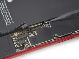
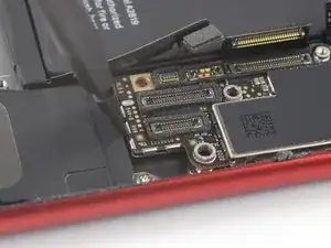
    • Use the pointed end of a spudger to disconnect the Lightning port cable by prying the connector straight up from its socket.

    • Use the pointed end of a spudger to disconnect the wireless charging coil cable by prying the connector straight up from its socket.

  54. qFIclOcVyZlKUyhO
    qFIclOcVyZlKUyhO
    R6skuXv5HwwTEjhG
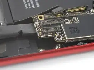
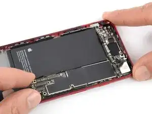
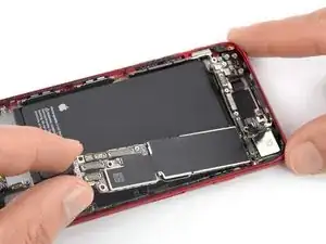
    • Use the flat end of a spudger to gently pry up the battery connector end of the logic board.

    • Be careful not to pry against any cables. If you feel resistance, check that all cables, connectors, and components are clear of the board.

  55. gUH5vRPtAi2jZYJE
    gUH5vRPtAi2jZYJE
    Lw6utUQWMZIGiXQB
    c5VCxdWgWh6yBcpj
    • Grasping it by the edges, lift the logic board near the battery connector and remove it.

    • Make sure that none of the surrounding cables are tangled with the logic board or blocking its way.

  56. YBZFUqCADeqUTBJX
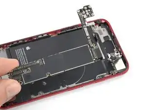
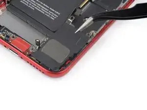
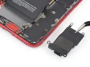
    • Unfasten the two screws securing the loudspeaker:

    • One 1.4 mm-long Phillips screw

    • One 2.1 mm-long Phillips screw

  57. obOcYd3OBTGhWKe1
    obOcYd3OBTGhWKe1
    lYRZWKxXa3ss2OvW
    saI4oRqTZGM52nw3
    • Use a pair of tweezers to remove the loudspeaker.

  58. YHfHEm2UVlc1xqtG
    YHfHEm2UVlc1xqtG
    1bfCACqP5V6DFSTy
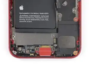
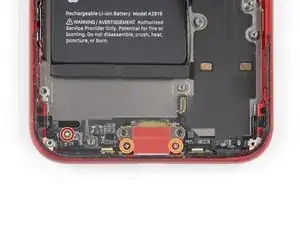
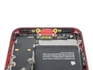
    • Unfasten the five screws securing the lighting connector to the rear case:

    • One 1.3 mm-long Phillips screw

    • Two 2.3 mm-long Phillips screws

    • Two 1.4 mm-long Phillips screws

  59. YcZEAXEKlPtHtcma
    YcZEAXEKlPtHtcma
    clbcAUr6Ugrje21P
    CCuLDuoI4XuObYCo
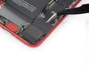
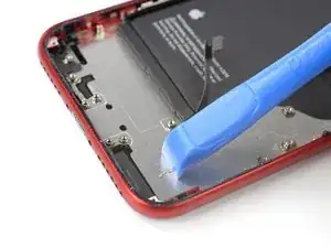
    • Use the pointed end of a spudger to gently pry the two microphones on the left and right of the Lightning connector free from the adhesive securing them in place.

    • Don't try to completely remove the microphones; just separate the adhesive as shown.

  60. 5WEHBfYBToRu4BwJ
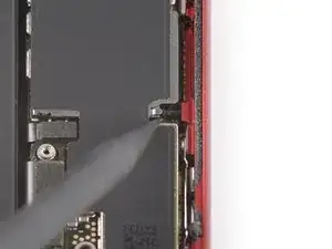
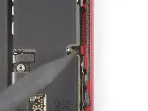
    • Apply a heated iOpener to the bottom of the rear case to loosen the charging port assembly adhesive, angling it as shown.

  61. qGSML2FPWIAT1NXs
    qGSML2FPWIAT1NXs
    o3DCrauS6lSLDTKn
    gM4aUJeIa2FIKGwk
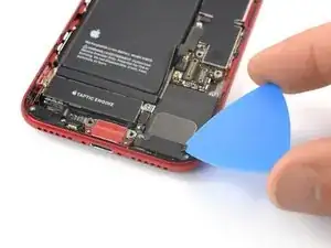
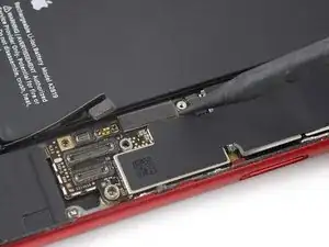
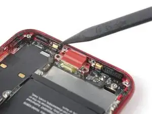
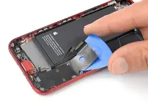
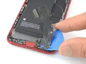
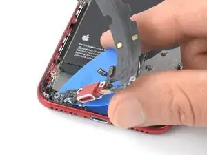
    • Slide an opening pick underneath the top portion of the Lightning connector assembly flex cable, and begin separating the cable from the rear case.

    • Part of the wireless charging coil lies directly underneath this portion of the Lightning connector flex cable. Aggressive prying may damage the coil.

    • If needed, use your hair dryer or iOpener repeatedly to re-heat the area behind the Lightning connector assembly flex cable in order to further soften its adhesive.

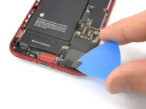
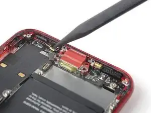
    • Continue separating the upper portion of the flex cable, being careful not to damage any other components along the way.

    • Keep the battery connector gently folded out of the way to avoid damaging it.

    • Be very careful not to damage the battery itself. A punctured battery can leak dangerous chemicals and/or catch fire.

    • Stop sliding the pick once it passes the lower edge of the battery.

  62. JRLi6uDNESQPOA2X
    JRLi6uDNESQPOA2X
    2A2RLX2cCs52wZOI
    rbc2gtfMCTWAEBtH
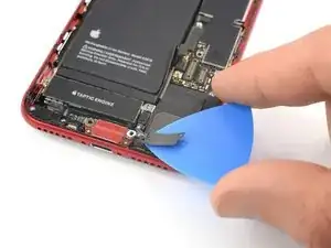
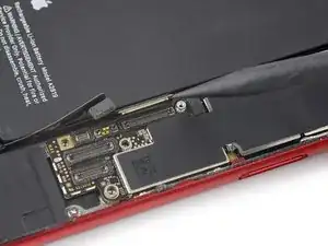
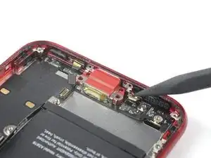
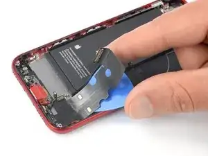
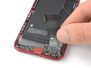
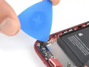
    • Starting at the corner of the phone, slide the pick underneath the cable towards the Lightning connector.

    • Stop sliding the pick when it reaches the Lightning connector.

  63. rSN1fFWw1yG54HuY
    rSN1fFWw1yG54HuY
    LKwEuiDXZi5C2B61
    • Gently pull the Lightning connector out of its recess in the rear case.

    • Don't try to remove the lightning connector assembly all the way yet. It is still partly adhered to the rear case.

  64. C6Qeg2VBXLjMPC62
    C6Qeg2VBXLjMPC62
    ffJAREIv6CwZoq2K
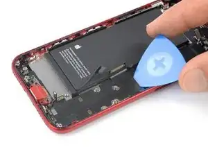
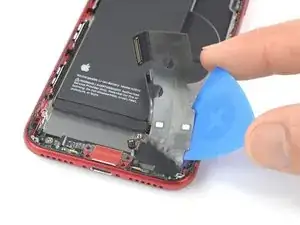
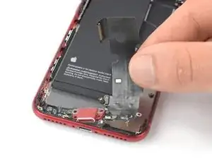
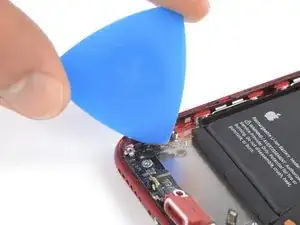
    • Slide an opening pick below the Lightning connector to further separate the assembly from the rear case.

    • Continue to slide the pick until the Lightning connector assembly is no longer adhered to the bottom of the rear case.

    • Don't try to remove the lightning connector assembly all the way yet. A last bit is still adhered to the left edge of the rear case.

  65. yLBFdSWXuoFFYMdG
    yLBFdSWXuoFFYMdG
    MtBoe4BDMdbW2liF
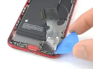
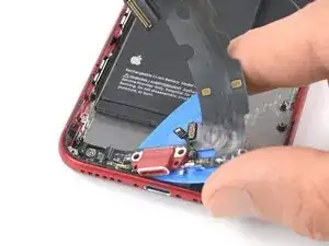
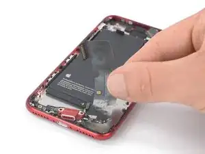
    • Slide an opening pick between the left edge of the rear case and the remaining adhered section of the Lightning assembly.

  66. ojNObrqLEsRUxQNe
    ojNObrqLEsRUxQNe
    ieGSLKxBZiSGqrDq
    LNWYDSbEJD2jdfFN
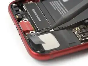
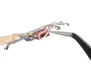
    • Remove the Lightning connector assembly.

    • Before installing or replacing the Lightning connector assembly:

    • Remove any remaining adhesive, and clean the glued areas with isopropyl alcohol and a lint-free cloth.

    • Before removing the adhesive backing on a new assembly, make sure the Lightning connector assembly is correctly positioned by aligning the hole in the flex cable with the screw post. If the cable is misaligned, you won't be able to reconnect it to the logic board.

  67. RSbxUZ1fAxkOMKLx
    RSbxUZ1fAxkOMKLx
    hnuJVUW63wJwkshR
    dFA3xDbQWHMVicBV
    • A rubber gasket on the bottom of the Lightning connector protects your iPhone from liquid and dust intrusion. If you are installing a new Lightning connector assembly, you may need to carefully remove and transfer the gasket to the new part.

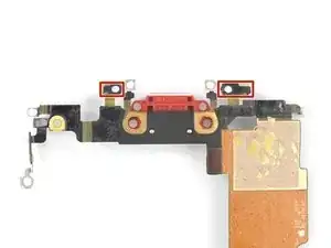
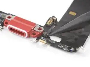
    • The small adhesive patch on the bottom of each microphone also protects your iPhone from liquid and dust intrusion. For best results, replace the two adhesive patches before installing your Lightning connector assembly.

    • Check if your new part comes with an antenna converter cable. If it doesn't, use the pointed end of your spudger to pry up and transfer the cable from your old Lightning assembly to the new one.

Conclusion

If possible, turn on your device and test your repair before installing new adhesive and resealing.

Compare your new replacement part to the original part—you may need to transfer other remaining components or remove additional adhesive backings from the new part before installing.

To reassemble your device, follow these instructions in reverse order.

Take your e-waste to an R2 or e-Stewards certified recycler.

Repair didn’t go as planned? Try some basic troubleshooting, or ask our Answers community for help.

Dominik Schnabelrauch

Member since: 23/11/16

201162 Reputation

0 comments