Introduction

  1. sOIRgiQcH51vLyiY
    sOIRgiQcH51vLyiY
    EiY2q4a6T3JRpgWZ
    GvJGl4OB4ALPhEx4
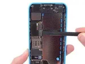
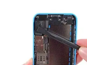
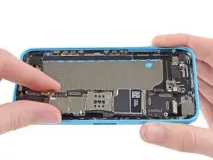
    • Use a spudger to disconnect the Lightning connector ribbon cable from its socket on the logic board.

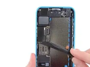
    • The Lightning connector cable is lightly adhered to a shield on the logic board. Use the flat end of a spudger to gently peel the cable up.

  2. TAotfFZ1DO5LeD5J
    TAotfFZ1DO5LeD5J
    rBAnR2BDUe5paa3k
    • Flip the Lightning connector cable up out of the way of the logic board.

  3. xPMjROE4IdFPO4Sr
    • Disconnect the lower antenna connector from the base of the logic board.

  4. dZY3tZvMAFwDimxy
    dZY3tZvMAFwDimxy
    xATOENdVxAeAL3do
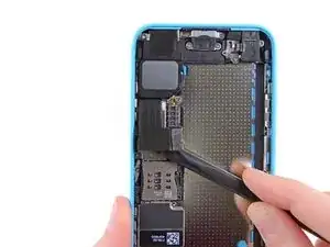
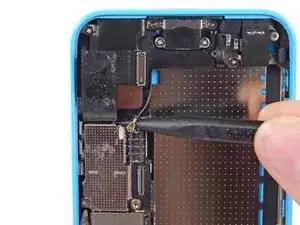
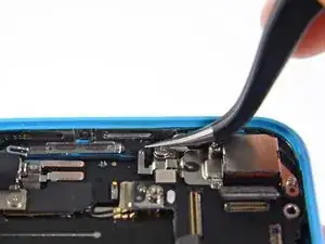
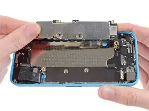
    • Use the flat end of a spudger to disconnect the audio control cable connector from its socket on the logic board.

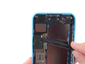
    • Disconnect the rear-facing camera cable connector from its socket on the logic board.

  5. ZRyQeQs5kUsw6LaV
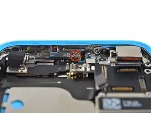
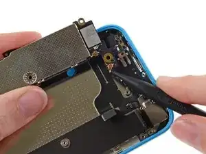
    • A small piece of tape may obscure the logic board grounding clip. If so, use a pair of tweezers to remove the tape.

  6. oPCyvts6fM2oQWRr
    oPCyvts6fM2oQWRr
    CDSvUDZMeMOjpAKO
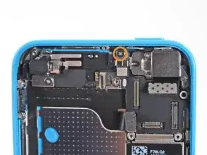
    • Remove the following screws securing the logic board grounding clip to the rear case:

    • 1.2 mm Phillips #000 in the top side-wall

    • 2.5 mm Phillips #000

  7. nJFlPmLljZwFWSpf
    • Use tweezers to remove the logic board grounding clip.

  8. vw51H2eJInfYfTtA
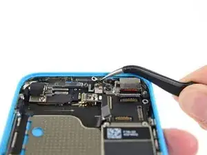
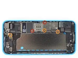
    • Remove the following screws securing the logic board to the rear case:

    • Two 2.3 mm Phillips screws

    • Three 2.7 mm standoff screws

    • Standoff screws are best removed with a standoff screwdriver or standoff driver bit. A small flathead screwdriver can also do the job—but use extra caution to ensure it doesn't slip and damage surrounding components.

  9. RWpWda3EJkhSMb1y
    RWpWda3EJkhSMb1y
    XXHZTI2XpEWGrruW
    eV5jARwQ3hlWsEQn
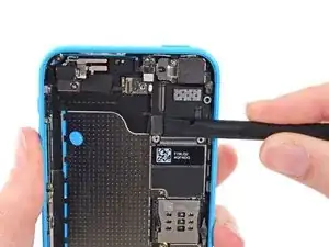
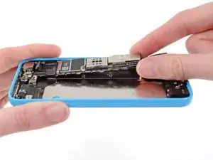
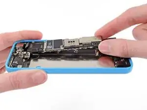
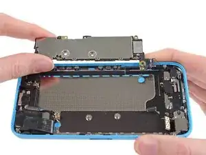
    • Holding the phone level, lift the bottom end of the logic board up enough to grasp it with your fingers.

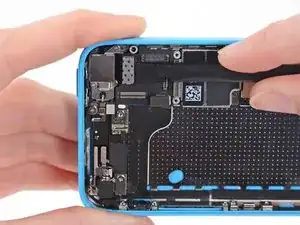
    • Pull the logic board away from the rear-facing camera just enough to expose the gold contact cap under the top end of the board.

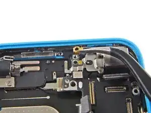
    • Remove the gold-colored contact cap from the threaded post in the rear case, and set it aside.

    On reassembly, it was tricky for me to figure out where the gold clip went. It goes against the back case, upside down and holds the logic board grounding clip, mentioned in Step 34. The upper hole of the grounding clip goes into the gold one, with the opening of the gold one oriented to the right. The 1.2 mm Phillips #000 in the top side-wall, removed in Step 33, holds them both together.

    Linda Groat -

  10. ZbLkNYUuWBExPGlQ
    ZbLkNYUuWBExPGlQ
    LTNdUEtUrIoBQPue
    • Flip the logic board up toward the volume control buttons to expose the antenna connector.

    • Do not try to remove the logic board from the rear case yet, as it is still connected by an antenna cable on the back.

    On this step, a small threaded barrel came off of the bottom of the housing, once I lifted off the logic board. Upon reassembly, it goes back in with the tiny threaded part down, into the silver piece near the rear facing camera. There is a little hole in the silver to receive it. When the logic board goes back down it matches up with a small silver hole and then secured to the rear case with the 2.7 mm standoff screw furthest to the left in the photo in Step 35. Take care not to put the barrel in upside down because it is very hard to get unscrewed once placed incorrectly.

    Linda Groat -

  11. Qo1cVHArVFU4mEVB
    • Disconnect the antenna connector from the back of the logic board.

  12. EHLDe1hNxjKlELm5
    • Remove the logic board from the rear case.

Conclusion

To reassemble your device, follow these instructions in reverse order.

Andrew Optimus Goldheart

Member since: 17/10/09

502341 Reputation

0 comments