Introduction
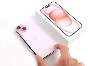
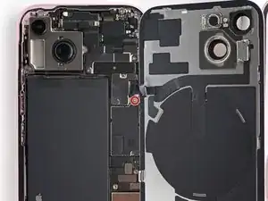
Use this guide to remove or replace the logic board in your iPhone 15.
You'll need replacement back glass and screen adhesive to complete this repair.
If your battery is swollen, take appropriate precautions and consider replacing your battery.
Due to Apple's parts pairing restrictions, much of your iPhone's functionality depends on the logic board—and without Apple's proprietary calibration process, even a genuine replacement logic board won't work. To retain full functionality, you must also replace the following parts with ones that are paired to your replacement logic board:
- Screen (to retain True Tone and Auto-Brightness)
- Front Camera and Sensors (most functionality)
- Battery (to retain battery health data)
-
-
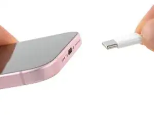
Unplug any cables from your phone.
-
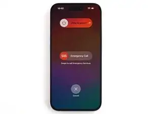
Hold the power and either volume buttons and slide to power off your phone.
-
-
-
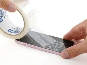
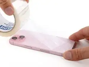
If your screen or back glass is badly cracked, lay overlapping strips of packing tape over the glass to protect yourself and make disassembly easier.
-
-
-
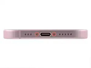
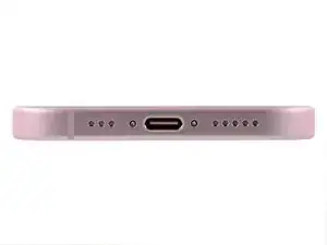
Use a P2 pentalobe driver to remove the two 7.7 mm-long screws on either side of the charging port.
-
-
-
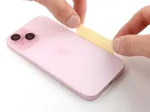
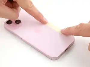
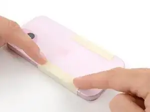
Cut two strips of tape, apply them along the long edges of the phone, and fold them over the back glass to secure it.
-
-
-
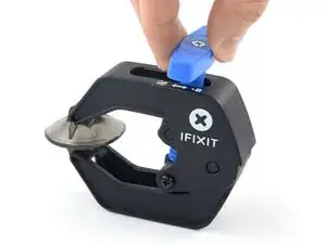
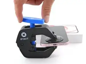
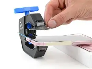
Pull the Anti-Clamp's blue handle backward to unlock the arms.
-
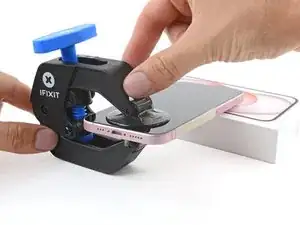
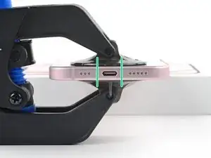
With the screen facing up, slide the arms over the left edge of your phone, with one suction cup on the screen and the other on the back glass. Center the suction cups near the bottom edge.
-
Support your phone so it rests level while between the Anti-Clamp's arms—a small box works well.
-
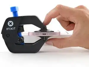
Squeeze the cups together to create suction.
-
-
-
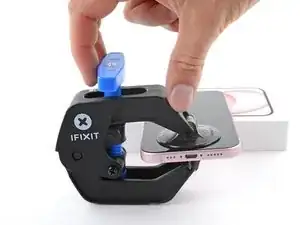
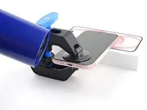
Pull the blue handle forward to lock the arms.
-
Turn the handle one full turn (360 degrees) or until the cups start to stretch.
-
As the cups stretch, make sure they stay vertically aligned with each other. If they tend to slip, remove the Anti-Clamp and apply tape for the cups to stick to.
-
-
-
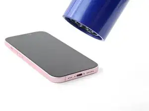
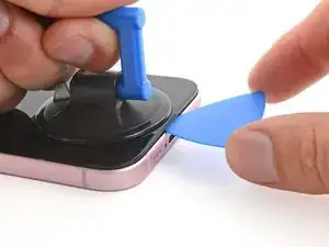
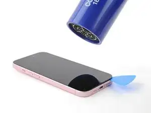
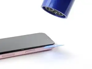
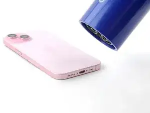
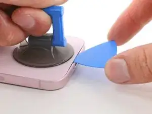
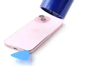
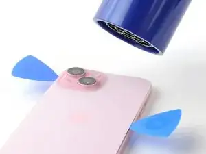
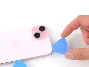
Use a hair dryer or heat gun to heat the bottom edge of the screen until it's hot to the touch.
-
Wait up to a minute for the adhesive to separate and a gap to form between the screen and the frame.
-
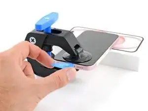
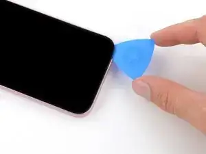
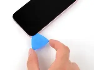
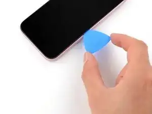
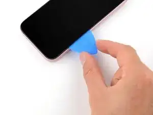
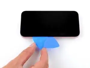
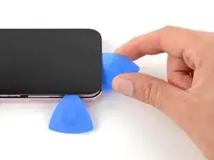
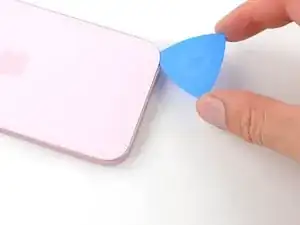
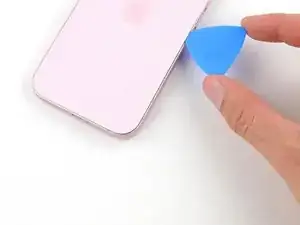
Insert an opening pick into the gap.
-
Remove the Anti-Clamp using the pull tabs on the suction cups.
-
Skip the next two steps.
-
-
-
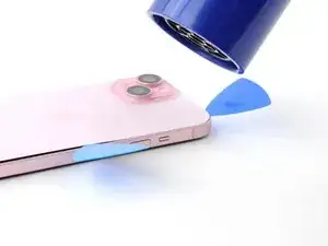
Use a hair dryer or heat gun to heat the bottom edge of the screen until it's hot to the touch.
-
-
-
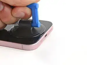
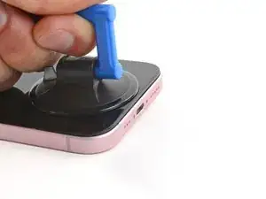
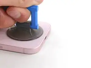
Apply a suction handle to the bottom edge of the screen.
-
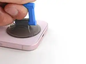
Pull up on the handle with a strong, steady force to create a gap between the screen and the frame.
-
Insert the tip of an opening pick into the gap.
-
-
-
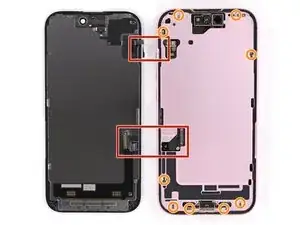
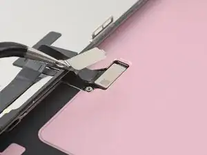
There are two delicate cables connecting the screen to the phone, one just above the mute switch, and the other about halfway between the volume down button and the bottom of the phone.
-
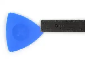
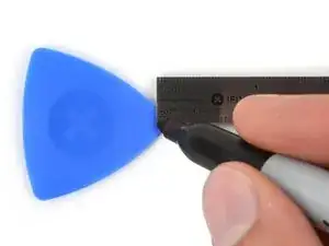
There are multiple spring contacts around the perimeter of the phone. Be extra careful not to insert your pick deeper than suggested in these locations to avoid bending the contacts.
-
-
-
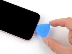
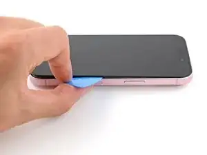
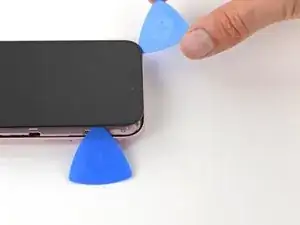
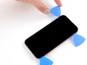
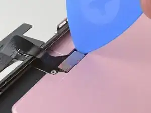
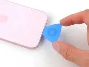
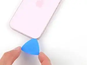
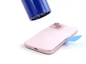
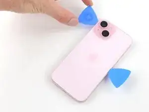
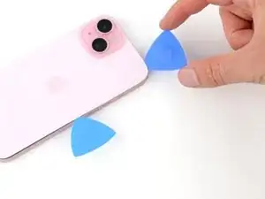
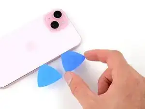
Slide your pick back and forth along the bottom edge to separate the adhesive.
-
Leave your pick inserted in the bottom right corner to prevent the adhesive from re-sealing.
-
-
-
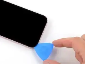
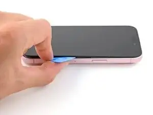
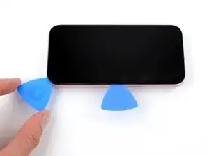
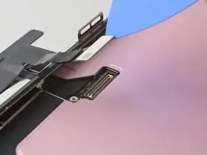
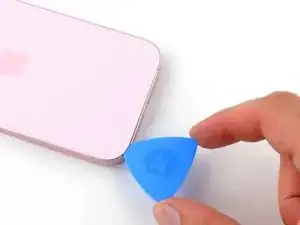
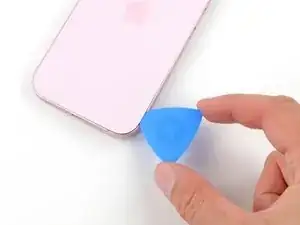
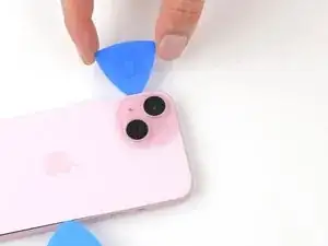
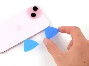
Slide your pick around the bottom right corner of the screen and toward the power button until you feel a hard stop at a clip securing the screen.
-
Rotate your pick so the flat edge is under the screen.
-
-
-
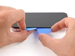
Hold the pick with one hand and twist it to increase the gap between the screen and the frame and release the right clip.
-
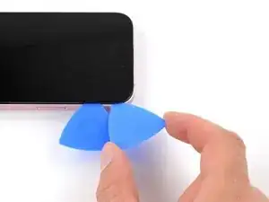
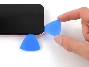
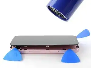
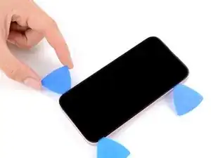
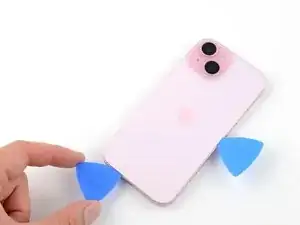
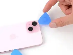
Insert a second opening pick to the right of the first one.
-
-
-
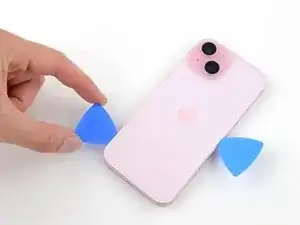
Slide the first pick back to the bottom right corner of the screen.
-
Slide the second pick to the top right corner of the screen to separate the adhesive.
-
Leave these picks inserted to prevent the adhesive from resealing.
-
-
-
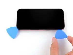
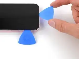
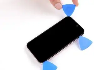
Insert a third opening pick in the top right corner, just above the previous pick.
-
Slide your pick around the top right corner and along the top edge until you feel it stop against the top left screen clip.
-
-
-
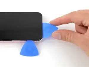
Rotate your pick so its flat edge is under the screen.
-
Twist your pick to release the top left screen clip.
-
Slide your pick to the top left corner.
-
-
-
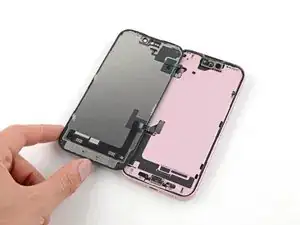
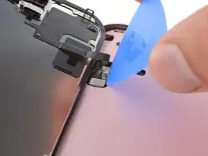
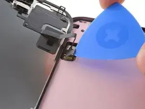
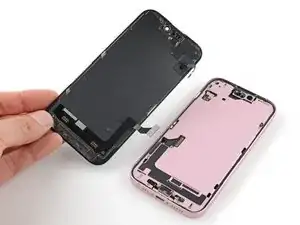
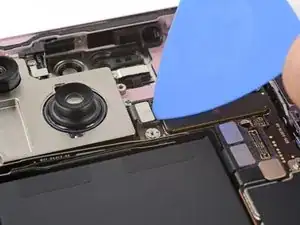
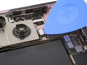
Slide your pick around the top left corner of the screen and along the left edge to release the clips and separate the adhesive securing it.
-
-
-
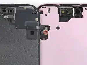
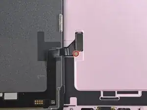
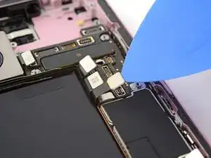
Use a tri-point Y000 driver to remove the 0.9 mm-long screw securing the front sensor connector cover.
-
-
-
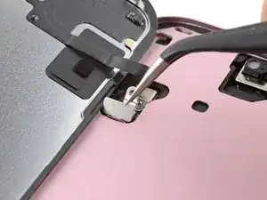
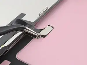
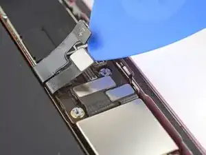
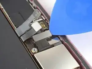
Use tweezers to lift the cover to a 90-degree angle.
-
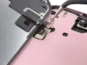
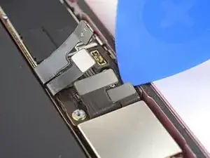
Unhook the cover from its slot in the logic board.
-
Remove the cover.
-
-
-
Use your tri-point Y000 driver to remove the 0.9 mm screw securing the screen connector cover.
-
-
-
Use tweezers to lift the cover and unlatch it from its hook on the logic board.
-
Remove the cover.
-
-
-
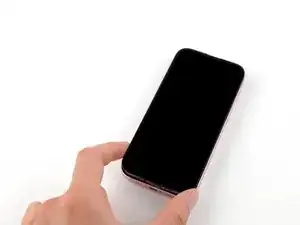
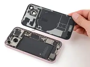
Flip your phone over and lay it on a soft surface, such as a microfiber cloth, to protect its internals as you work.
-
-
-
Use a hair dryer or heat gun to heat the bottom edge of the back glass until it's hot to the touch.
-
-
-
Apply a suction handle to the bottom edge of the back glass.
-
Pull up on the handle with a strong, steady force to create a gap between the back glass and the frame.
-
Insert the tip of an opening pick into the gap.
-
-
-
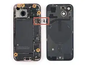
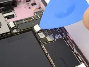
There's a delicate cable connecting the back glass to the phone, right next to the volume down button. Don't insert your pick here to avoid slicing the cable.
-
There are multiple spring contacts around the perimeter of the phone. Be extra careful not to insert your pick deeper than suggested in each step to avoid bending these contacts.
-
-
-
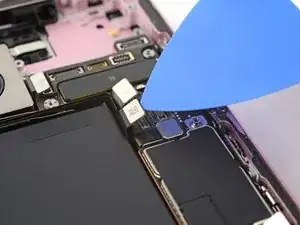
Slide your pick back and forth along the bottom edge to separate the adhesive.
-
Leave your pick inserted in the bottom right corner to prevent the adhesive from re-sealing.
-
-
-
Rotate your pick around the bottom right corner and slide it to the volume down button or until you feel a hard stop at a large clip securing the back glass.
-
Leave this pick inserted to prevent the adhesive from resealing.
-
-
-
Insert a second opening pick at the bottom edge.
-
Rotate the second pick around the bottom left corner.
-
Slide this pick up to the top left corner to separate the adhesive.
-
Leave this pick inserted to prevent the adhesive from resealing.
-
-
-
Rotate your second opening pick around the top left corner and slide it to the top right corner to separate the adhesive.
-
Leave this pick in place to prevent the adhesive from resealing.
-
-
-
Rotate the second opening pick around the top right corner and slide it to the volume up button to separate the adhesive.
-
-
-
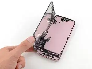
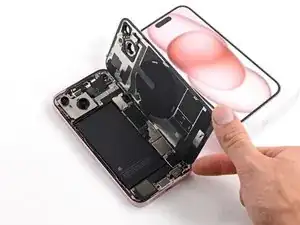
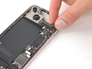
Gently swing open the back glass to the right of the phone.
-
Rest the back glass against a raised surface so it doesn't strain the cable.
-
-
-
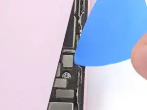
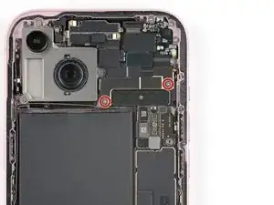
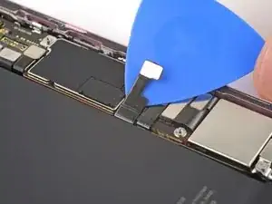
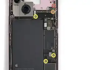
Use a tri-point Y000 driver to remove the two 1.3 mm-long screws securing the lower connector cover.
-
-
-
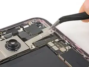
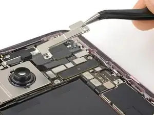
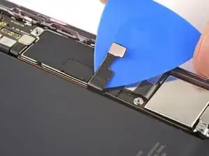
Use tweezers to slide the cover toward the top of the phone to unlatch it from the logic board.
-
Remove the cover.
-
-
-
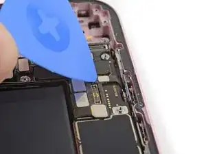
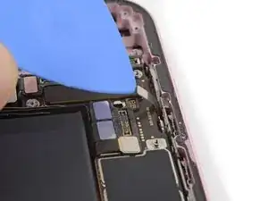
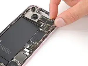
Hold the back glass upright with one hand and rotate it just enough to reveal the battery press connector just below the volume buttons.
-
Use the tip of an opening pick to pry up and disconnect the battery press connector from the logic board.
-
-
-
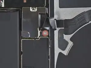
Use your tri-point Y000 driver to remove the 0.9 mm-long screw securing the middle connector cover.
-
-
-
Use the flat end of a spudger or your finger to push the cover toward the bottom of the phone and unclip its top edge.
-
Remove the cover.
-
-
-
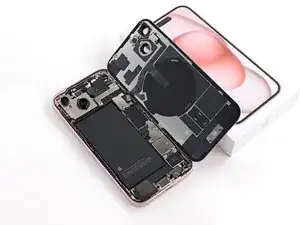
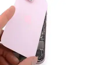
Remove the back glass.
-
This is a good point to test your repair before sealing up your phone. Temporarily reconnect the battery and back glass, power on your phone, and make sure it works as expected. Power it back down and continue reassembly.
-
Use this guide to reapply adhesive and install your back glass.
-
-
-
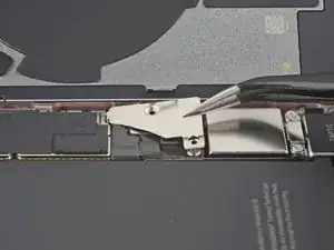
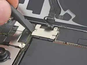
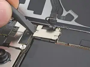
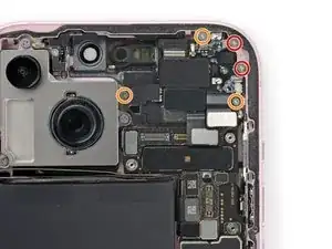
Use your tri-point Y000 driver to remove the two 1.3 mm screws securing the upper connector cover.
-
Remove the cover.
-
-
-
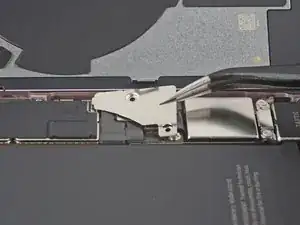
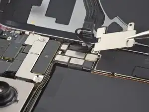
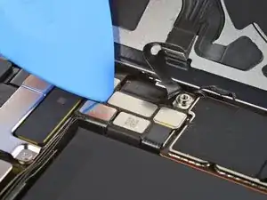
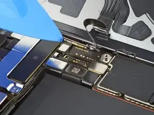
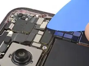
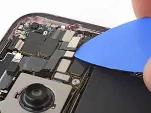
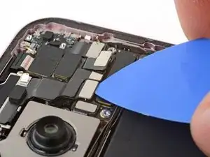
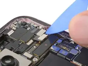
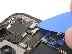
Use the tip of an opening pick to pry up and disconnect the antenna, front sensors, and front camera press connectors (three connectors in total).
-
-
-
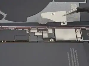
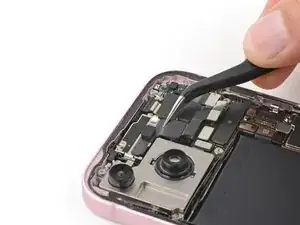
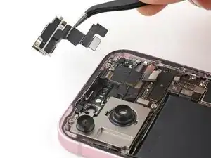
Use tweezers or your fingers to pull the front camera and sensors out of their recess in the frame and remove them.
-
-
-
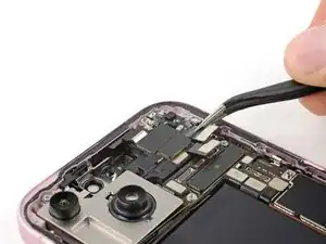
Use the tip of an opening pick to pry up and disconnect the earpiece speaker press connector.
-
-
-
Use a Phillips #000 driver to remove the five screws securing the earpiece speaker:
-
Two 1.1 mm screws
-
Three 1.6 mm screws
-
-
-
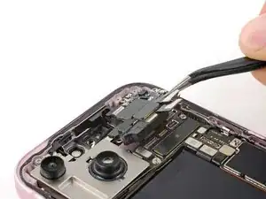
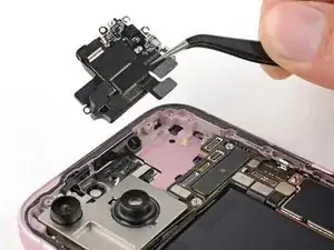
Use tweezers or your fingers to lift and pull the earpiece speaker away from the top of the phone to free the gasket from the frame.
-
Remove the earpiece speaker.
-
-
-
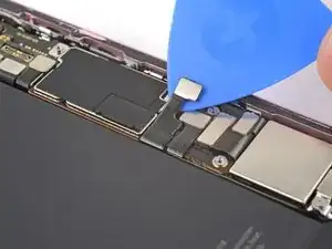
Disconnect the eSIM, Taptic Engine, and charging port press connectors (three connectors in total).
-
-
-
Use your standoff driver to remove the five standoff screws securing the logic board:
-
One 2.9 mm screw
-
One 3.9 mm screw
-
Three 3.5 mm screws
-
-
-
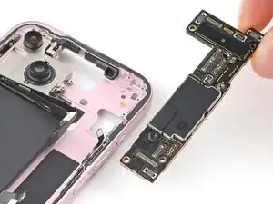
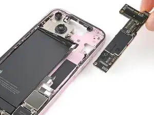
Grip the top edge of the logic board and gently pull it out from under the cables.
-
Remove the logic board.
-


To reassemble your phone, follow these instructions in reverse order.
Take your e-waste to an R2 or e-Stewards certified recycler.
Repair didn’t go as planned? Try some basic troubleshooting, or ask our Answers community for help.