Introduction

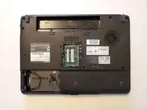
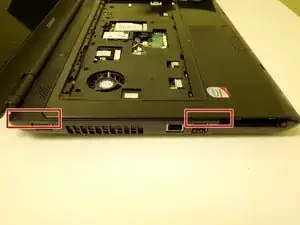
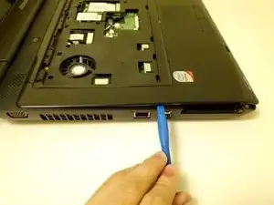
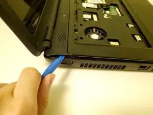
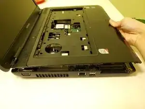
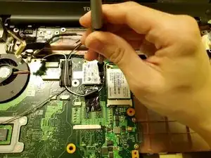
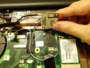
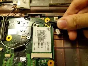
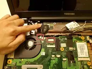
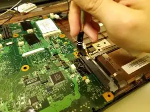
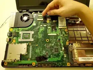
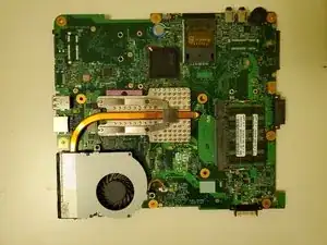
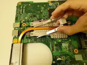
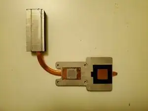
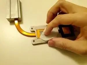
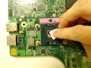
This guide will show you how to replace the CPU thermal paste in a Toshiba Satellite L300-04P (PSLB8C-04P01X) laptop. The thermal paste is an important compound found between the CPU and CPU cooling system, responsible for conducting the heat from the CPU to the CPU cooler. The thermal paste bridges the microscopic gap between the CPU die and CPU cooler heatsink surface, maintaining thermal conductivity. Old or degraded thermal paste will reduce thermal conductivity, resulting in higher CPU temperatures and increased thermal stress.

Before beginning, ensure the device is powered off and unplugged. Please familiarize yourself on how to clean and apply new thermal paste as required in steps 26 and 27. Additionally, it is recommended to use an anti static wrist strap to prevent damage from static electricity.

Note that there are other variants of this device, varying in processor and memory configurations with model specific codes (PSLB0x, PSLB1x, PSLB2x, and PSLB3x). For those variants, the internal hardware may vary from the model shown in this guide.


  1. MCFpVl5tobDsYqXu
    MCFpVl5tobDsYqXu
    HwNmBKPpL4QdcRIZ
    WVwE6mAEPpmUCMds
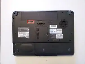
    • Unlock the battery by sliding the left battery latch to the right.

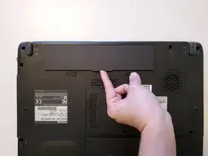
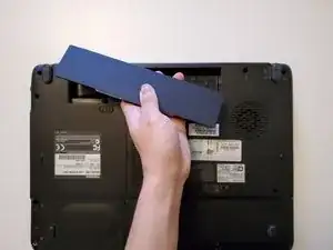
    • To remove the battery, hold the spring-loaded right battery latch to the right, then grasp the center battery tab and pull upward.

  2. JU5AXkOOeUHS5eXN
    JU5AXkOOeUHS5eXN
    HHCAmUMTHASVmsIj
    JDnT23xcyUHtKPoh
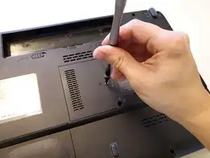
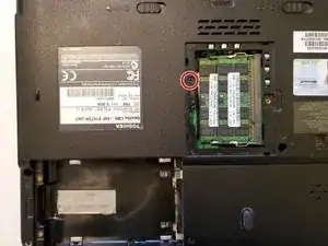
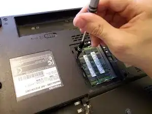
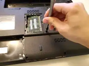
    • Use a Phillips #00 screwdriver to loosen the RAM cover and 2.5 inch HDD cover captive screws.

  3. jlGTdjTv6lBAgVxH
    jlGTdjTv6lBAgVxH
    oZXTGVLm6xVvVcIl
    4vpcYUBcX4QaZJKF
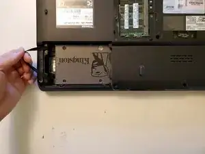
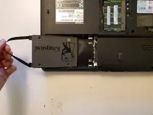
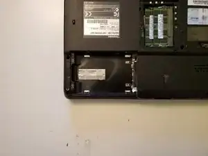
    • Gently pull the caddy pull strap outwards then upwards to remove the HDD assembly.

    • Do not immediately pull upwards on the HDD, as this will bend the connector resulting in damage.

  4. mEZQCKoukQLGCfpY
    mEZQCKoukQLGCfpY
    lQgyuvnnmxniJgHT
    • Use a Phillips #00 screwdriver to remove the M2.5x6 optical drive retaining screw.

  5. cffpKypYwXpcX5yX
    cffpKypYwXpcX5yX
    TdL6Kbn2s3jRBPsC
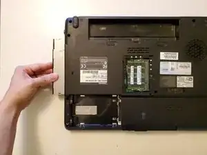
    • Locate the gray optical drive screw bracket, then gently push outwards to release the optical drive.

    • Grasp the edge of the optical drive and pull outwards to remove it from the device.

    • The optical drive bracket is tucked underneath the bottom chassis cover where the optical drive screw hole is located.

  6. GeMFmGEwj61qUaRM
    GeMFmGEwj61qUaRM
    yaie2WVGKOWTVMGj
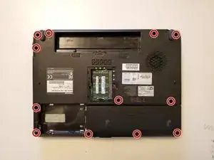
    • Use a Phillips #00 screwdriver to remove the twelve M2.5x6 bottom chassis screws.

  7. qtRxJlkJ1VNXlDiG
    qtRxJlkJ1VNXlDiG
    vxRPY1JUnUN5VnmR
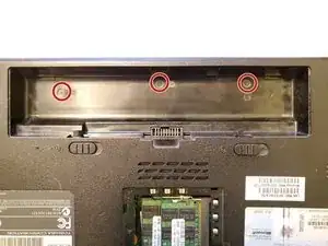
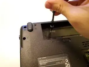
    • Use a Phillips #000 screwdriver to remove the three M2x3 inner battery compartment screws.

  8. mCGidTLETvk2EVV6
    mCGidTLETvk2EVV6
    xTIBSQcNxeIKvron
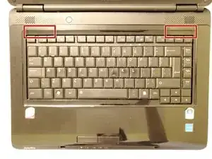
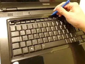
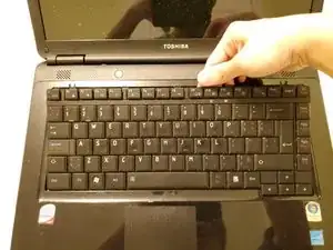
    • Place the device keyboard side up, then use an opening tool to gently remove the top keyboard bezel.

    • To prevent damage to the plastic clips, pry the keyboard bezel up at a shallow angle until the entire assembly is free.

  9. CEKPBiIJEyq1UUk1
    CEKPBiIJEyq1UUk1
    hxMPWIOrnLQZZJPd
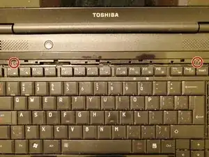
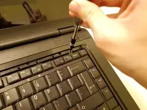
    • Using a Phillips #00 screwdriver, remove the two M2x3 keyboard retaining screws.

  10. 2bkWdHqFSSCVEpRt
    2bkWdHqFSSCVEpRt
    b1b3HvGr2P1RQxWa
    G2J6QYw62eIIZSJA
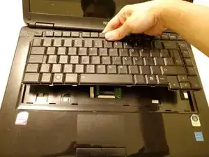
    • Lift the top of the keyboard up and towards the front of the device, then gently pull backwards to release the bottom of the keyboard.

    • Do not immediately pull the keyboard away, as this will damage the ribbon cable underneath.

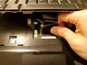
    • Gently pull the ribbon cable out of its connector to release the keyboard.

    • To reconnect the ribbon cable, align the connector parallel to the socket, then gently push the connector into the socket.

  11. rqeOYyUeF6NGiwaM
    rqeOYyUeF6NGiwaM
    LBwLAGRUNmLsSV3n
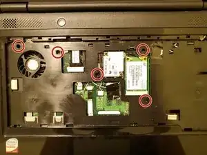
    • Using a Phillips #00 screwdriver, remove the five M2.5x6 top cover screws

  12. NNmZ2W2X5ctqPEuq
    NNmZ2W2X5ctqPEuq
    GnNaAUorKKt13AKI
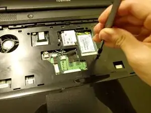
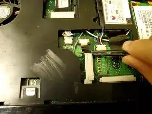
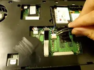
    • Use tweezers to gently pull and unplug the touchpad ribbon cable.

    • Unplug the speaker connector by gently prying both ends with the tweezer until the connector comes loose.

    • To reconnect the touchpad, hold the black plastic tab with tweezers or a finger, then align the connector parallel to the socket. This prevents the cable from flexing as it is inserted into the socket.

  13. D24nC44obNvHiXQh
    D24nC44obNvHiXQh
    WLWBDCL3DK5vvCGK
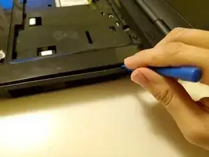
    • Begin removing the top cover by gently prying apart the right side using the opening tool. Start by finding a gap near the empty DVD drive bay.

    • The right side is free when the top cover sits loosely above the bottom cover.

  14. uC4LxfuWEuTJQLIm
    uC4LxfuWEuTJQLIm
    AKIM1awIoFCy2spH
    QDGOseKGGBkryPRu
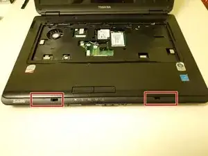
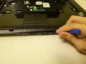
    • To release the front of the top cover, use an opening tool or a spudger to pry around the two lid latch holes at the front of the device, starting from the right side.

    • To prevent damage to the front volume wheel and SD card reader, ensure the opening tool does not reach into those areas.

  15. 3ayBw2ZfOR6FtJMB
    3ayBw2ZfOR6FtJMB
    LWRXg6ePvh5B6BhK
    LFx1KdPmUgFYdsOO
    • Finish releasing the top cover by prying the left side, first above the USB ports, then near the rear hinge.

  16. dkHgtAnxljMDwVb3
    dkHgtAnxljMDwVb3
    tx1t5hQQZuIFgwGy
    • Grab the front of the top cover, push backwards slightly to ensure the rear hinge clips are free, then pull up and towards the front of the device to remove the top cover.

  17. ZdGJaTY63QKZ3RTj
    ZdGJaTY63QKZ3RTj
    m2TqLEMvW2oT42pU
    ACgGIAUBkBKSLkQJ
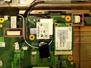
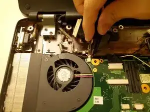
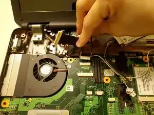
    • Using fingers or tweezers, unplug the display ribbon cable and DC power cable.

    • Take a picture to remember cable layout and routing for reassembly.

  18. adBDkqAuKoZcQA5O
    adBDkqAuKoZcQA5O
    sjJKGYlZSDtknpyU
    YgXSUsNpZttjLTaw
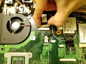
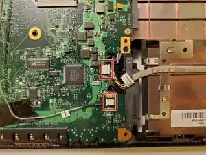
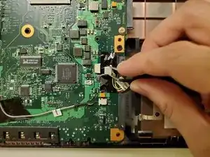
    • Using fingers or tweezers, unplug the USB port cable and microphone wire.

  19. 42UYkL4xB2XUSvNh
    42UYkL4xB2XUSvNh
    KctskSAEUpS4EFDr
    M2LIsy4fTDXE3vPI
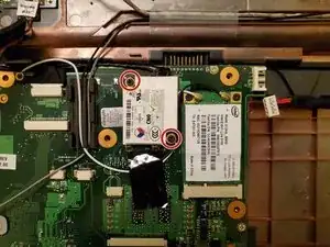
    • Use a Phillips #00 screwdriver to remove the two M2x3 modem card screws.

    • Pull upwards on the modem card to release it from the press-fit connector.

  20. tGQwWZM2nvncIJDb
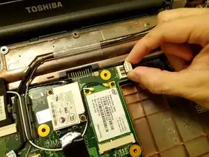
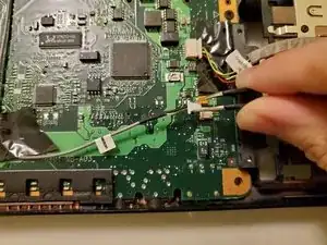
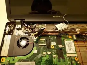
    • Using tweezers, gently pull upwards and unplug the wireless card antenna wires from the coaxial connectors.

    • To reassemble, use tweezers to hold the wire terminal directly over the card connector, then press downwards. A misaligned connector could bend the center pin, resulting in damage.

  21. wimCwVVn4kDGcSEH
    wimCwVVn4kDGcSEH
    EKtLCXtRvQNbjjd6
    maZOmKBGuOjvpLb3
    • Using fingers or tweezers, unplug the power button cable and webcam cable.

  22. 2VZNqSaNlFlGIfYF
    2VZNqSaNlFlGIfYF
    qJNUPvaEgUrCxGNj
    3wtE4gXiO3Mj1eYM
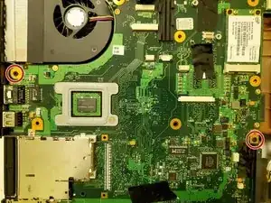
    • Before removing the motherboard from the chassis, ensure all wires are tucked away to prevent snagging.

    • Use a Phillips #00 screwdriver to remove the two M2.5x6 motherboard screws.

  23. NkAZKqokoPKxZxaS
    NkAZKqokoPKxZxaS
    aDHooChPMkgOlQ2j
    • Grab the top of the motherboard, then pull upwards and towards the back of the device to remove the motherboard.

    • Do not immediately pull the motherboard upwards, as the front volume wheel and SD card reader will get caught on the bottom chassis, resulting in damage.

    • Lay the motherboard on a clean flat surface so that the CPU cooler is visible, as shown in the second picture.

  24. scfZYBsMemMCvYdA
    scfZYBsMemMCvYdA
    ovpZYCT2nXH5Rvpy
    1VhSyZNFiyT3Pvtc
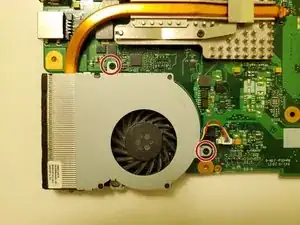
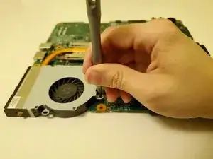
    • Using a 2mm Phillips screwdriver, remove the 2 M2x3 CPU fan screws.

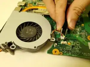
    • Using tweezers, gently unplug the CPU fan cable, then remove the CPU fan from the cooler.

    • There may be significant dust build up between the fan and cooler. Use a soft brush or compressed air to remove the dust.

  25. NjyaVkmrryDYhtKx
    NjyaVkmrryDYhtKx
    d55Ht4nX1aPNSqmC
    1MpX3NuWLHSxMVxh
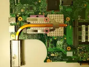
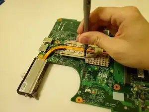
    • Use a Phillips #00 screwdriver to remove the two M2x3 heat sink bracket screws.

  26. ZNlvXHBQdhkQd6gZ
    ZNlvXHBQdhkQd6gZ
    cLZ2qUMhKIPIdUmU
    sveuuPjVpP35tEHb
    • Remove the CPU cooler and place it with the copper heat plates facing upwards.

    • Wet the paper towel with high concentration Isopropyl Alcohol, then proceed to wipe away any old thermal paste on the copper heat plate.

    • Using a new piece of paper towel, wet with Isopropyl alcohol and wipe away any old thermal paste on the CPU die.

    • Do not touch the exposed CPU die with fingers. Body oil will negatively affect thermal transfer between the CPU and cooler.

    • If unsure on how to perform this step, please see the guide on how to clean and apply thermal paste.

  27. 6KKpQYYRHJeWtwbV
    6KKpQYYRHJeWtwbV
    1yUAGp5uyFXpHdIR
    • Ensure the CPU and cooler are both free of any residue and completely dry of Isopropyl alcohol.

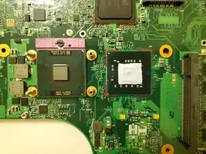
    • Next to the CPU is the integrated GPU, covered by a thermal pad. If this pad is stuck to the CPU cooler, use a spudger to carefully remove the pad from the cooler and place it over the integrated GPU as shown in the first picture.

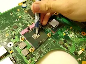
    • Using the thermal paste, apply a small, pea-sized drop directly over the CPU.

    • When reassembling, align the CPU cooler then press down evenly to ensure the thermal paste is evenly spread for best thermal performance.

Conclusion

To reassemble your device, follow these instructions in reverse order.
Nathan L

Member since: 17/01/23

373 Reputation

0 comments