Introduction

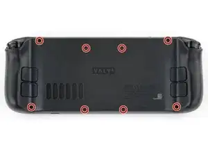
This guide demonstrates how to remove the left thumbstick in your Steam Deck OLED.

  1. wg1CPbiBgYbiTVlf
    wg1CPbiBgYbiTVlf
    nJjXUM3KksnJHIgN
    mLdVpQ6WWvINGWuE
    • Turn on your Steam Deck and allow the battery to discharge below 25% before starting your repairs, as a charged lithium-ion polymer battery can be dangerous if accidentally punctured.

    • As an extra precaution, Valve recommends putting your Steam Deck into battery storage mode within the BIOS before starting any internal repairs. Read how to do that here.

    • Power down your Steam Deck and unplug any cables.

    • If you have a microSD card installed, make sure to remove it before opening the Steam Deck. If you attempt to remove the back cover with it still installed, it could snap right in half.

    • During your repair, it can be helpful at times to lay the Steam Deck face-down in its case to protect the thumbsticks and prevent wobble.

  2. CU2nvWsgJGWI2Rut
    CU2nvWsgJGWI2Rut
    HUaIpoLKT3gGOD53
    • Use a T6 Torx driver to remove the eight 5.8 mm‑long screws securing the back cover.

    • Throughout this repair, keep track of each screw and make sure it goes back exactly where it came from.

  3. rEBEVxNkrDU5dsek
    rEBEVxNkrDU5dsek
    rIRRhvkBKVWODhWI
    A4aS52mtPxxkwit5
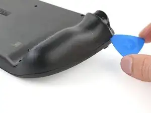
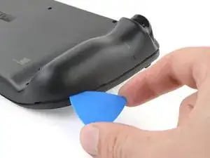
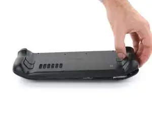
    • Insert an opening pick at an upward angle between the back cover and the front shell near one of the triggers.

    • If you can't insert your pick here, try along the top or bottom edges of the Steam Deck OLED before sliding it toward the handle.

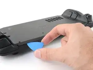
    • Slide your pick along the edge of the handle to release the clips securing it to the front shell.

  4. yYcl1PRUGUuYu2AV
    yYcl1PRUGUuYu2AV
    Z61KAZVNuuuFxgBL
    5ji5HRJa5qu1niLI
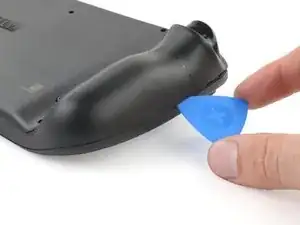
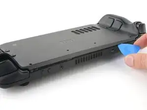
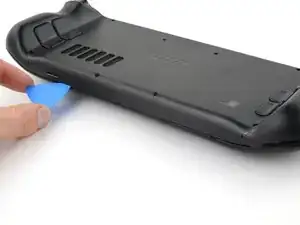
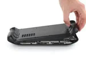
    • Reinsert your pick and slide it along the top and bottom edges until the back cover feels loose.

  5. 3hO2o6jhWtTFtqUB
    3hO2o6jhWtTFtqUB
    HZa1Pau2KaJcrM1I
    2pXBrjoLgvKGSFGx
    • Grip the unclipped handle and pull it away from the front shell to release the remaining clips.

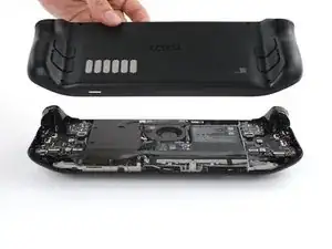
    • Remove the back cover.

  6. OKJYYpHQNvn4X1nk
    OKJYYpHQNvn4X1nk
    GaA5rrvDLfGCHRBc
    d6WmlRapenltwItT
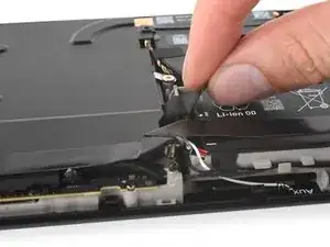
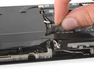
    • Grip the battery cable pull tab, located to the left of the battery.

    • Firmly pull the battery cable straight away from the motherboard shield (toward the battery) to disconnect it.

    • This bundled cable is fairly stiff. If you're having trouble, re-grip the pull tab close to the head of the connector and gently walk it side-to-side as you pull.

    • If the cable pull-tab feels fragile or rips during this process, remove the motherboard shield and disconnect the cable using a spudger.

    • When the battery cable comes free, it might push up on the motherboard shield. Don't worry, as this won't damage anything.

    The pull tab can come off revealing the wires. The instructions should be updated to reflect that catch.

    Khurram Tariq -

  7. eVyqGZ4gRjIItCdp
    eVyqGZ4gRjIItCdp
    6GnJOi2TBm2xBjBf
    B6yPGCjDkG2tF2l2
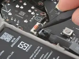
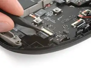
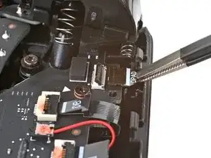
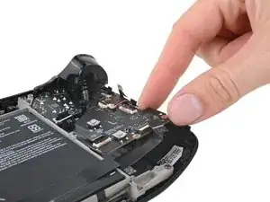
    • Use the point of a spudger to flip up the small locking flap on the left thumbstick ZIF connector.

    • The pull tab on this connector may be labeled TS.

    • Use tweezers or your fingers to grip the cable's pull tab and slide the connector straight out of its socket to disconnect it.

  8. KugQMVSQlXCoHHpq
    KugQMVSQlXCoHHpq
    bh2YKolmHSrlIATR
    AGkZCpDeG6MbiNwq
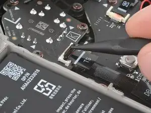
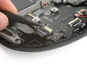
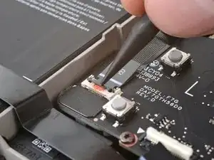
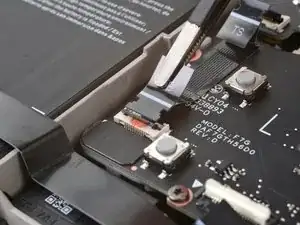
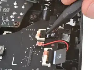
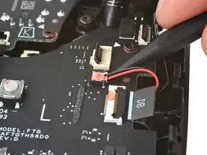
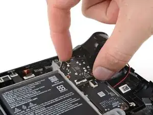
    • Use a spudger to flip up the small white locking flap on the left button board interconnect cable ZIF connector.

    • The pull tab on this connector may be labeled C‑L.

    • Use tweezers or your fingers to grip the cable's pull tab and slide it straight out of its socket to disconnect it.

  9. 5Wpu2epSRv2mGfIN
    5Wpu2epSRv2mGfIN
    TOPmeppCxEKHxihY
    knln22XHApnSEJBa
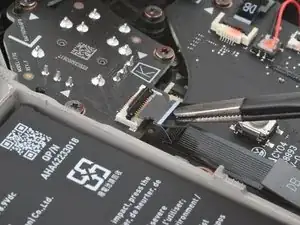
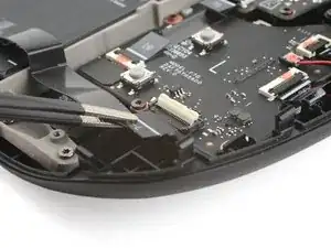
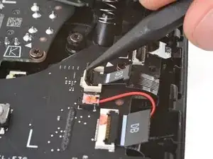
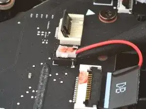
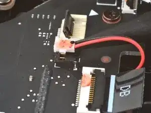
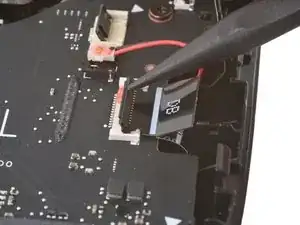
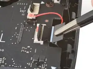
    • Flip up the small black locking flap on the left thumbstick cable ZIF connector.

    • The pull tab on this connector may be labeled DB.

    • Slide the connector straight out of its socket to disconnect it.

  10. GJLN2rLTrWkiFOUH
    GJLN2rLTrWkiFOUH
    6UOYL36SigdGcbgP
    JJHH6XgVanIrMIRk
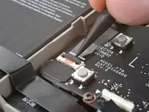
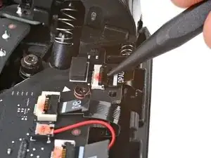
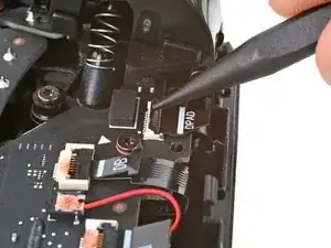
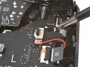
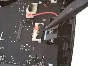
    • Flip up the small locking flap on the D‑pad ZIF connector, located in the top right corner.

    • The pull tab on this connector may be labeled DPAD.

    • Slide the connector straight out of its socket to disconnect it.

  11. BVejwhkTLmgMXjOW
    BVejwhkTLmgMXjOW
    xmAWcTUQtUtIClZy
    3vlBieEZ2nPvLpMv
    • Flip up the small locking flap on the touchpad board cable ZIF connector, located just below the previous one.

    • The pull tabs on the remaining ZIF connectors in this procedure may be labeled DB.

    • Lift the connector until its arms are free and slide it straight out to disconnect it.

  12. DbVyqinevJkGBYDC
    DbVyqinevJkGBYDC
    hS4AQNkRRXwRfcnJ
    g6HGGCnjy2sxIScp
    • If you aren't replacing your button board, you can leave this cable connected and lay the board over the right side of the frame after you've removed the screws.

    • Be careful when disconnecting the haptics, as the cables and connector are very delicate. Pry only on the base of the white connector and not on the cables or socket.

    • Insert the point of your spudger under the neck of the haptics cable connector.

    • Gently pry up to disconnect it.

  13. sCWdmHus3MOVNeNq
    sCWdmHus3MOVNeNq
    OnJLOLS36xxsKSeG
    3JPOqrNKLIDsvTAj
    • Flip up the small locking flap on the touchpad board cable ZIF connector, located just below the haptics connector.

    • Slide the connector straight out of its socket to disconnect it.

  14. cOIKQHKUqYVTHJOi
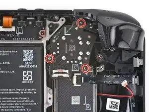
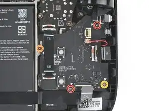
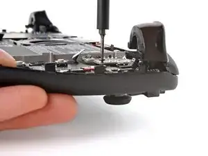
    • Use your T6 Torx driver to remove the four screws securing the left button board:

    • Two 5.9 mm‑long screws

    • One 3.8 mm‑long screw

    • One 4.9 mm‑long screw

  15. pX1UssAk2xMkmgOX
    pX1UssAk2xMkmgOX
    WanxYJnJ2DyvT1dP
    2T4VnkJIuhBq1Uxp
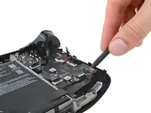
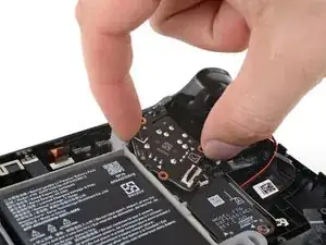
    • Insert the point of your spudger between the bottom right corner of the button board and the frame.

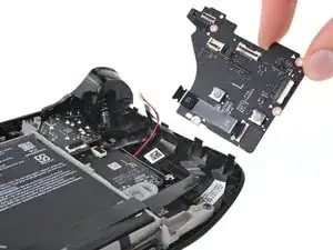
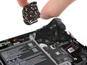
    • Pry up until you can grab the button board with your fingers.

    • Remove the button board.

    • During reassembly, make sure none of the five cables become trapped underneath the button board as you lay it into place.

  16. t2gi5PvE6MmUVrTK
    t2gi5PvE6MmUVrTK
    4AXsHBD1mrPCwHOt
    • Use your T6 Torx driver to remove the three 5.9 mm‑long screws securing the right thumbstick.

    • During reassembly, hold the Steam Deck OLED off your work surface so it doesn't rest on your thumbstick as you tighten the screws.

  17. cwu4fxlpQwN1OoJd
    cwu4fxlpQwN1OoJd
    nCveaUlCe4Ldod3V
    2DusZkdXLy2kKqkW
    • Grip the edges of the thumbstick board and rotate it counterclockwise to clear the trigger.

    • Remove the thumbstick.

Conclusion

To reassemble your device, follow these instructions in reverse order.

Clay Eickemeyer

Member since: 19/09/22

65196 Reputation

0 comments