Introduction

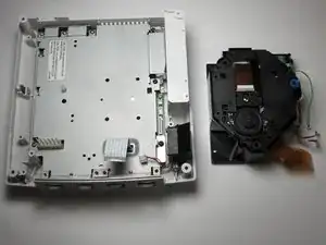
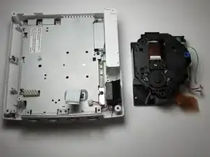
This guide details how to replace a failed GD-ROM drive with a new working drive.

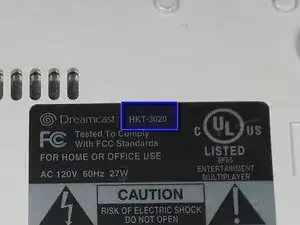
Be sure to replace the GD-ROM with one corresponding to your model number. Refer to the Top Cover Disassembly Guide for instructions on where to find your model number.

Problem with this guide: The photos incorrectly show the power supply has been removed.

  1. rdFJlNVwMtT3hJRD
    rdFJlNVwMtT3hJRD
    BGojrPldMPBm4Yew
    • Verify that the console is disconnected from the AC outlet before you begin.

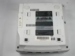
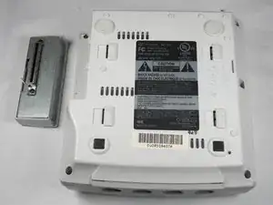
    • Flip the console over on its back.

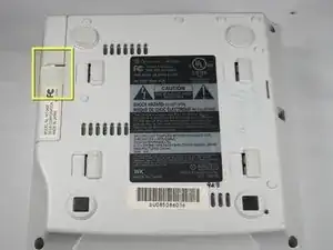
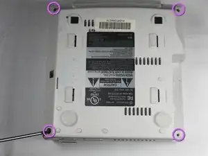
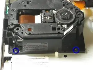
    • Take note of your model number, in case replacement parts are needed.

  2. HDbDfaw3TOGBMCHi
    HDbDfaw3TOGBMCHi
    b12VKhkOV53BrRt3
    ZxvUK2uvuTY4pH1H
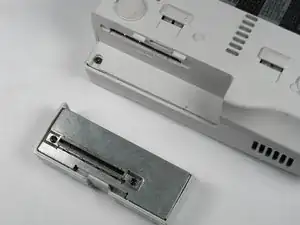
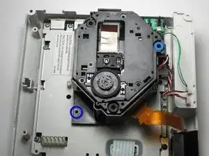
    • Remove the expansion bay by applying pressure to the small clip on the expansion bay while prying it away from the console.

  3. j4mn2GW3UHoTNIAH
    • Locate and remove all four black 12mm Phillips #02 screws from the underside of the console.

    • Note: Remove the expansion bay to locate the fourth screw

  4. KGQFrciudkmBDQJX
    • Internal components can be loose. Be careful that they do not fall out when removing the cover.

    • Turn the console right side up.

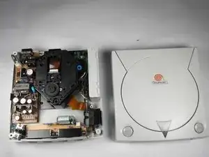
    • Remove the top cover by gently lifting the upper portion of the console.

  5. UqnkwsEhKXEaDccZ
    UqnkwsEhKXEaDccZ
    WCnVuvsLWJUYqnId
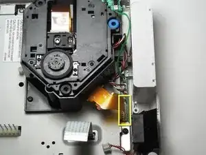
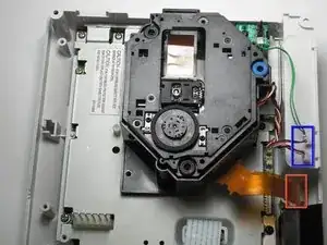
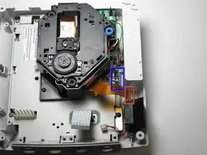
    • Detach the orange cable by giving it a gentle pull while wiggling the cable back and forth until it loosens from the logic board.

  6. ms2ncVxe2h4NQsNb
    ms2ncVxe2h4NQsNb
    TUZoEl54cKfFU6EM
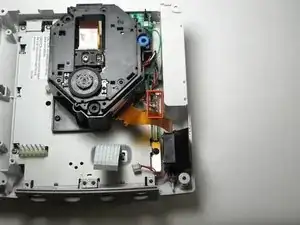
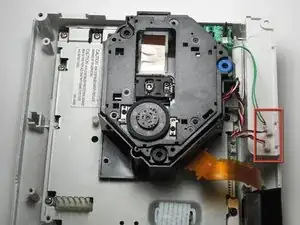
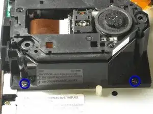
    • Detach the cables by gently pulling the three GD-ROM cables to remove them from the logic board.

  7. P6mDmXfpjHs3QMpt
    P6mDmXfpjHs3QMpt
    noSoOLAmlYwJyxMN
    • Remove the two black 12mm Philips #02 screws located on the left side of the GD-ROM bracket.

    • The console is rotated 90 degrees counter-clockwise in the first photo. The second photo depicts the normal position.

  8. S65eQ5lEBJeGT5aj
    S65eQ5lEBJeGT5aj
    rFmcoWxRScGUCISp
    • When lifting the GD-ROM, be careful that the top half of the casing does not detached from its base.

    • Remove the GD-ROM by gently lifting it from its base.

  9. kiMF4YjoScW5Fhu3
    kiMF4YjoScW5Fhu3
    CjOsojBPrleUesTo
    • Replace the bad GD-ROM drive with a functional one.

  10. hLbhRpGfLgBrZ3G3
    hLbhRpGfLgBrZ3G3
    fNpWmricEHFwRpPI
    • Secure the new GD-ROM drive to the console with the Philips #2 screws.

  11. jSR5BclhKHUpR41b
    jSR5BclhKHUpR41b
    ZQy5KIHJFmF16BPH
    byjRXnO3mfeGVK1G
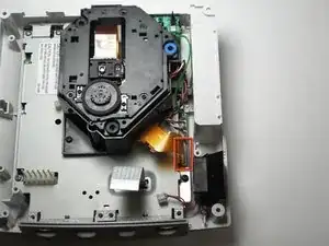
    • Connect the three GD-ROM cables to the logic board.

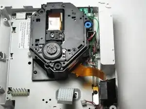
    • Connect the GD-ROM data ribbon to the logic board.

Thorr686

Member since: 07/11/09

472 Reputation

One comment

If only it was that simple Sega screwed U.K gamers over with the fact we have to buy totally new consoles due to the wires of the disk drive being soldered in rather than clipped in.

Anthony Salmon -