Introduction
This is a prerequisite-only guide! This guide is part of another procedure and isn't meant to be used alone.
Tools
-
-
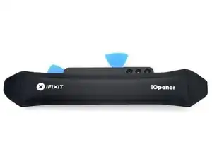
While you wait for the adhesive to soften, note the following:
-
There's adhesive securing the back cover around the perimeter of the frame.
-
-
-
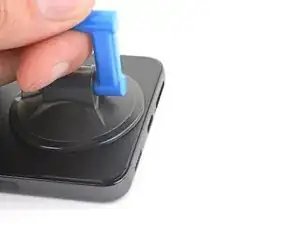
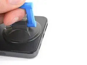
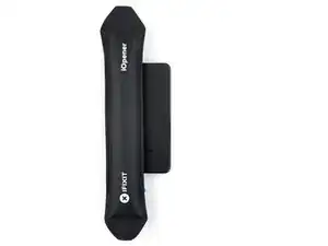
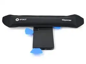
Apply a suction handle to the back cover, as close to the bottom edge as possible.
-
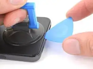
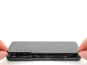
Pull up on the suction handle with strong, steady force to create a gap between the cover and the frame.
-
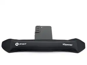
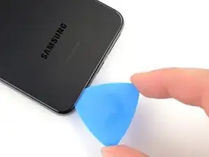
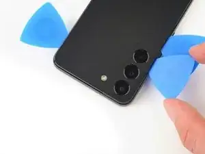
Insert an opening pick into the gap.
-
-
-
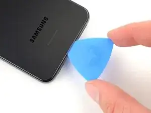
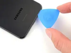
Slide the pick back and forth along the bottom edge to slice through the adhesive.
-
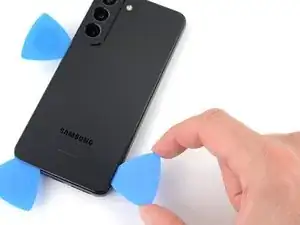
Leave the pick inserted in the bottom left corner to prevent the adhesive from resealing.
-
-
-
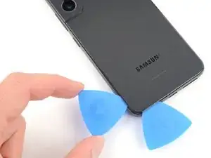
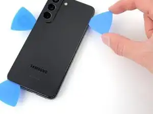
Insert a second opening pick at the bottom left corner.
-
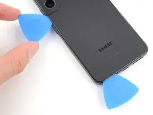
Slide the pick to the bottom of the camera bezel to slice the left adhesive.
-
Leave the pick in to prevent the adhesive from resealing.
-
-
-
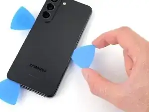
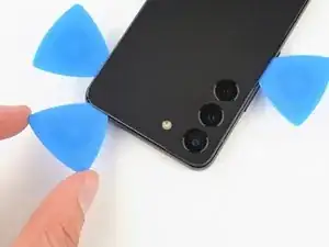
Insert a third opening pick at the bottom right corner.
-
Slide the pick to the top right corner to slice the adhesive.
-
Leave the pick in the top right corner to prevent the adhesive from resealing.
-
-
-
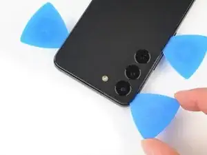
Insert an opening pick in the gap at the top right edge.
-
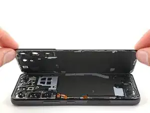
Slide the pick across the top edge and around the top left corner to slice the remaining adhesive.
-
-
-
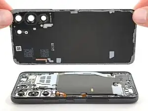
Grab and remove the back cover.
-
This is a good point to power on your phone and test all functions before sealing it up. Be sure to power your phone back down completely before you continue working.
-
Remove any adhesive chunks with a pair of tweezers or your fingers. Apply heat if you're having trouble separating the adhesive.
-
To apply new adhesive, follow this guide.
-
-
-
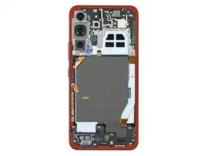
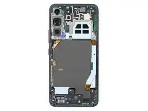
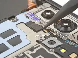
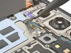
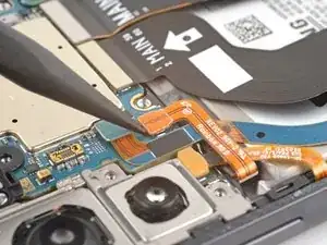
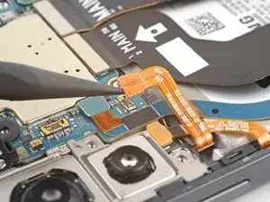
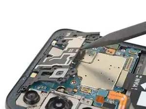
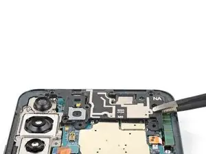
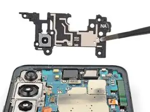
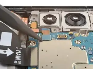
Use the pointed end of a spudger to pry and disconnect the wireless charging coil from the motherboard.
-
-
-
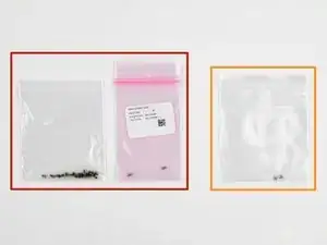
Label the bag with the most screws and the colored bag #3428.
-
If you're replacing the screen and battery, label the clear bag with two screws #3229.
-
-
-
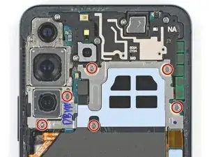
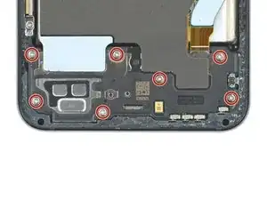
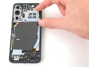
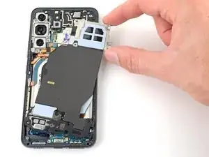
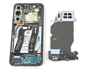
Use your Phillips screwdriver to remove the six 3.5 mm-long screws securing the wireless charging coil.
-
-
-
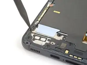
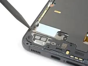
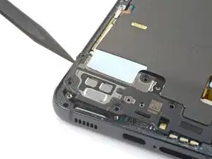
Insert the pointed end of your spudger between the upper left corner of the loudspeaker and the frame.
-
Pry up to unclip the loudspeaker from the frame.
-
-
-
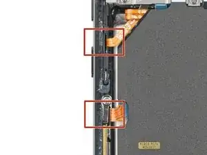
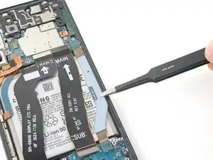
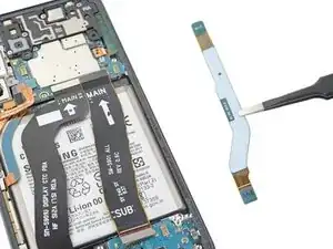
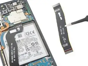
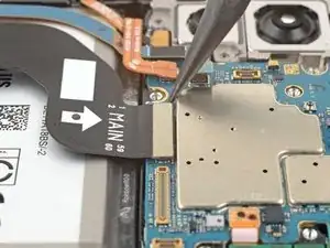
Use the pointed end of your spudger to pry up and disconnect both interconnect cables from the motherboard.
-
-
-
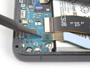
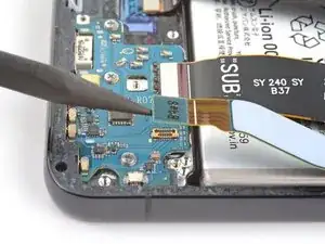
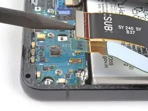
Use the pointed end of your spudger to pry up and disconnect both interconnect cables from the charging board.
-
-
-
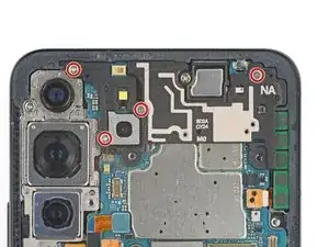
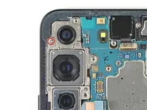
Use your Phillips screwdriver to remove the four 3.5 mm-long screws securing the motherboard cover.
-
-
-
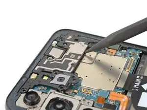
Insert the pointed end of your spudger between the bottom of the motherboard cover and the motherboard.
-
Pry up on the cover to unclip it from the frame.
-
-
-
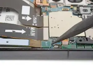
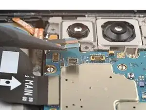
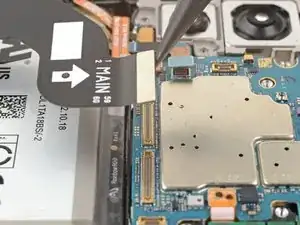
Use the pointed end of your spudger to pry up and disconnect the left 5G mmWave antenna press connector.
-
-
-
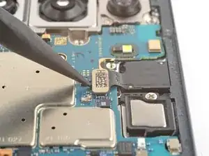
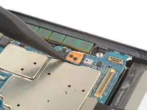
Use the pointed end of your spudger to pry up and disconnect the front-facing camera press connector.
-
-
-
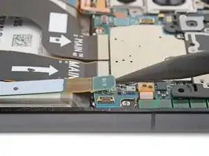
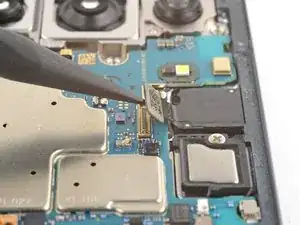
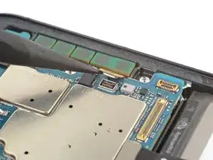
Use the pointed end of your spudger to pry up and disconnect the right 5G mmWave antenna press connector.
-
-
-
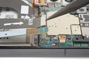
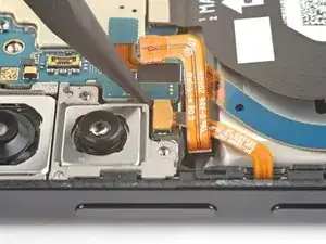
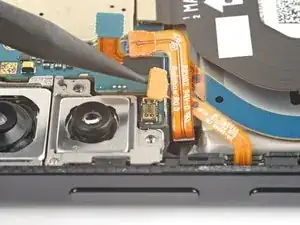
Use the pointed end of your spudger to pry up and disconnect the power and volume button's press connector.
-
-
-
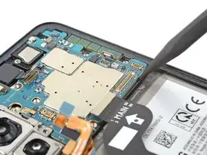
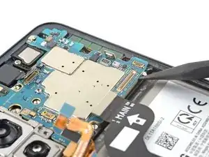
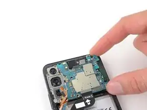
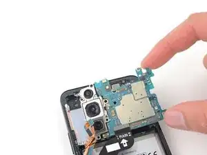
Insert the pointed end of your spudger between the bottom right of the motherboard and the frame.
-
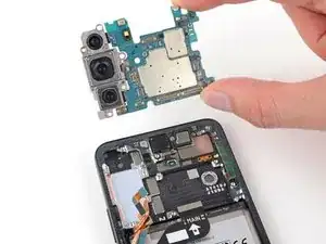
Pry the motherboard up until you can grab it with your fingers.
-
To reassemble your device, follow these instructions in reverse order.

