Introduction

Follow this guide to replace the screen and battery assembly on your Samsung Galaxy S21 Ultra with a genuine Samsung part.

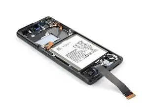
This guide is written for the genuine Samsung screen and battery assembly. The assembly consists of the screen, battery, and frame together in one part. Be sure you have the right part before you begin the repair.

Before you begin, refer to the Samsung Self-Repair document for safety information.

If your battery is swollen, take appropriate precautions. Before disassembling your device, completely discharge the battery. This reduces the risk of a dangerous thermal event if the battery is accidentally damaged during the repair.

Note: Retaining water resistance after the repair will depend on how well you reapply the adhesive, but your device will lose its IP (Ingress Protection) rating.

  1. CEanXxnVSSFDxULP
    CEanXxnVSSFDxULP
    JQj2FZTbjkwkqRAL
    Uy53JWljB4mv3gCW
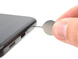
    • Insert a SIM eject tool, bit, or straightened paper clip into the SIM card tray hole on the top edge of the phone.

    • Press the SIM eject tool into the SIM card tray hole to eject the SIM card tray.

    • Remove the SIM card tray.

    • If you accidentally inserted the SIM eject tool into a microphone hole, don't worry! You most likely didn't damage the microphone.

  2. dnZwOwWRGYRSh2a2
    • Unplug and power off your phone before you begin.

    • Prepare an iOpener and apply it to the back cover for at least three minutes to loosen the adhesive underneath.

    • A hair dryer, heat gun, or hot plate may also be used, but be careful not to overheat the phone—the display and internal battery are both susceptible to heat damage.

    I have had no luck with the iOpener so far after heating it for 30 seconds. At what temperature does the glue become loose? I noticed that the iOpener heated up the back of the phone to up to 110F (43 C).

    Imtiaz Chowdhury -

    Hi Imtiaz,
    if you're struggling to get the adhesive loose enough you can try to reapply the iOpener several times or try using a hair dryer or heat gun instead. In terms of temperature, I'm afraid I can't give you an exact number for when it's high enough for the adhesive to loosen, as that varies by manufacturer and model.

    Dominik Schnabelrauch -

  3. mDJrMgKhCj3ytvQN
    mDJrMgKhCj3ytvQN
    LwoAPCrTWOmLkOUP
    N4Cc4MPaF6rt5eQy
    • Secure a suction handle to the bottom edge of the back cover, as close to the edge as possible.

    • If the back cover is badly cracked, covering it with a layer of clear packing tape may allow the suction cup to adhere. Alternatively, very strong tape may be used instead of the suction cup. If all else fails, you can superglue the suction cup to the broken cover.

    • Lift the back cover with the suction handle to create a small gap between the back cover and the frame.

    • If you have trouble creating a gap, apply more heat to further soften the adhesive. Follow the iOpener instructions to avoid overheating.

    • Insert an opening pick into the gap you created.

    • Slide the opening pick to the bottom left corner to slice the adhesive.

    • Leave the opening pick in place to prevent the adhesive from resealing.

  4. TlD1m5HNSPFuC5LB
    TlD1m5HNSPFuC5LB
    jw6QkMKFXAskwHWf
    • Insert a second opening pick at the bottom edge of your phone.

    • Slide the opening pick to the bottom right corner to slice the adhesive.

    • Leave the opening picks in place to prevent the adhesive from resealing.

  5. j3SEACBrPGVaWEDK
    j3SEACBrPGVaWEDK
    C1bhcnRMvGDHR61n
    wuMsuYbLPVwlmFod
    • If the adhesive becomes hard to cut, it has most likely cooled down. Use your iOpener for two to three minutes to reheat it.

    • Insert a third opening pick at the bottom right corner of your phone.

    • Slide the opening pick along the right edge of your phone to slice the adhesive.

    • Leave the opening pick in the top right corner to prevent the adhesive from resealing.

  6. r5HRUCDLtMj3fyyO
    r5HRUCDLtMj3fyyO
    vjxL4quOANhWcOEi
    NLmMABcELXiV6Xny
    • When you slice near the camera assembly, insert only the tip of the opening pick (~ 4-5 mm) to avoid damaging or smearing the camera.

    • Insert a fourth opening pick underneath the top right corner of your phone.

    • Slide the opening pick along the top edge to slice the adhesive.

    • Leave the opening pick in the top left corner to prevent the adhesive from resealing.

  7. XwLPlrxHlVakBeFJ
    XwLPlrxHlVakBeFJ
    xljXQVixhBbnr3kj
    CSK4HYitOnWMH4Zw
    • Insert a fifth opening pick underneath the top left corner.

    • Slide the opening pick along the left edge of the back cover to slice the remaining adhesive.

    • When you slice near the power button, insert only the tip of the opening pick (~ 3-4 mm) to avoid damaging the power and volume button flex cable.

  8. fiXBTtgsPT2nqtQX
    fiXBTtgsPT2nqtQX
    6VxOZGj6JMLjJgdp
    • Remove the back cover.

    • During reassembly:

    • This is a good point to power on your phone and test all functions before sealing it up. Be sure to power your phone back down completely before you continue working.

    • Remove any adhesive chunks with a pair of tweezers or your fingers. Apply heat if you're having trouble separating the adhesive.

    • If you're using Samsung custom-cut adhesives, follow this guide.

    • If you're using double-sided tape, follow this guide.

  9. wOjsQDOahS2MNSPr
    wOjsQDOahS2MNSPr
    pJUkyiASC3B53FQV
    • Insert an opening pick underneath the left bottom end of the NFC antenna and charging coil assembly.

    • Carefully slide the opening pick along the bottom left edge of the assembly to separate it from the battery.

    Note: Separate the charging coil from the battery only. The NFC antenna, charging coil, and loudspeaker will be removed as an assembly in step 15.

    Blaine Phillips -

  10. MECaJthFWMFW52vL
    MECaJthFWMFW52vL
    GCFwOPAPgIBlXNku
    • Use a spudger to disconnect the charging coil by prying the connector straight up from its socket.

  11. iK4P2TUaXmKb4VNs
    iK4P2TUaXmKb4VNs
    ZL4y1vAxlOuPu6ZF
    • Use a spudger to disconnect the NFC antenna by prying the connector straight up from its socket.

  12. oS1JRQXeTI5kv5DX
    oS1JRQXeTI5kv5DX
    BJiqHhxSZxmBjYyT
    • Use a Phillips screwdriver to remove the five 3.9 mm-long screws securing the NFC antenna and charging coil assembly.

    • If you're reassembling with the Samsung Self-Repair kit, be sure to replace the screws with new ones labeled #3427.

  13. OK2MQSd4YtSjmJLp
    OK2MQSd4YtSjmJLp
    HJWXsrSP3MeWMroP
    • Use a Phillips screwdriver to remove the four 3.9 mm-long screws securing the loudspeaker assembly.

    • If you're reassembling with the Samsung Self-Repair kit, be sure to replace the screws with new ones labeled #3427.

  14. d1QnDkTAjs1yKUsv
    d1QnDkTAjs1yKUsv
    tN3gBbKFqlIRdERa
    • Insert the tip of a spudger between the frame and the upper-left notch in the loudspeaker.

    • Pry up with the spudger to release the loudspeaker from its plastic clips.

    When reconnecting this be sure the left end (power button side) is inserted under the edge of the frame so that the piece is level with the frame. Then push the other sides in to hear a definite snap on the right and bottom.

    Thomas Hayes -

  15. hpiasYebqulAcDja
    hpiasYebqulAcDja
    JaSTWxsIyEjOeyZC
    • Use a pair of tweezers or your fingers to carefully remove the NFC antenna, charging coil, and loudspeaker assembly.

    • Set the assembly aside. You'll reuse it during reassembly.

    I think the thicker main cable is shown backwards (`Main` connection part of the cable is put on the daughterboard/subboard, and the vice versa is also true)

    Antonio GB -

  16. OiY4sZtW2XyyBvun
    OiY4sZtW2XyyBvun
    LZKDrE1efQZGxvsP
    • Use a spudger to pry up and disconnect the battery's press connector.

  17. 4Kn2bOXKvZjAFXlt
    4Kn2bOXKvZjAFXlt
    wcBvEDELUUhXMEbQ
    wFT1MBOqRqa5wjkF
    • Use a spudger to pry up and disconnect the primary and secondary interconnect cables' press connectors on the motherboard.

  18. ZXZhyNBibaIWwbBA
    ZXZhyNBibaIWwbBA
    qRxQesXZmdi5waQs
    4lG5PuWSbhnjkpDY
    • Use a spudger to disconnect the secondary interconnect cable from the daughterboard by prying its bottom connector straight up from its socket.

    • Use your fingers or a pair of tweezers to carefully remove the secondary interconnect cable.

    • Set the cable aside. You'll reuse it during reassembly.

    Personnellement je trouve que c'est moins risqué d'endommager les flex en les laissant branchés au circuit de charge

    Olivier Fafard -

  19. ypGlUsPDHuDxKbjk
    ypGlUsPDHuDxKbjk
    t5V5yMprN2Hfw3R1
    AIX4Q4YOtXlfD4SL
    • Use a spudger to disconnect the primary interconnect cable from the daughterboard by prying its bottom connector straight up from its socket.

    • Use your fingers or a pair of tweezers to carefully remove the primary interconnect cable.

    • Set the cable aside. You'll reuse it during reassembly.

  20. VwJDiNxEb4khmQmI
    VwJDiNxEb4khmQmI
    a2Go63FmXhPWIttd
    • Use a Phillips screwdriver to remove the three 3.4 mm-long screws securing the charging board.

    • If you're reassembling with the Samsung Self-Repair kit, be sure to replace the screws with new ones labeled #3428.

    Before the next step double check to be sure you removed the sim card tray, or you will likely break a piece off inside the charging board.

    Thomas Hayes -

    Hi Thomas.

    Thank you for the comment! I forgot to add the SIM card tray removal step to the beginning. I have added it!

    Alex Diaz-Kokaisl -

  21. bV4rd5ouUWUNVRRw
    bV4rd5ouUWUNVRRw
    a5SEis1OhZRUeXfJ
    • Insert the pointed end of a spudger underneath the left edge of the charging board next to the main flex cable connector.

    • Use your spudger to pry up the charging board.

  22. GYOiwMqaOyjCTGML
    GYOiwMqaOyjCTGML
    dXrTcbi2rqcj554W
    n1HRtH2aOQKjBkKJ
    • Use a pair of blunt tweezers or your fingers to remove the charging board. Start by lifting its top edge up and then carefully slide the USB-C connector out of its recess.

  23. dZ6Nv4IFmMnaiB2f
    dZ6Nv4IFmMnaiB2f
    PpjAkDIZGQYAUZ2b
    • Use a spudger to pry up and disconnect the left 5G mmWave antenna's press connector.

  24. sDQN5KnlVvA4KghD
    sDQN5KnlVvA4KghD
    RAPMAwSZFjYSKYWJ
    • Use a spudger to pry up and disconnect the right 5G mmWave antenna's press connector.

  25. IfMyabToEalxkrSm
    IfMyabToEalxkrSm
    w4tPyKRdvvAG5oCP
    • Use a Phillips screwdriver to remove the four 3.4 mm-long screws securing the 5G mmWave antennas.

    • If you're reassembling with the Samsung Self-Repair kit, be sure to replace the screws with new ones labeled #3428.

  26. KALgHBAcERSYC345
    KALgHBAcERSYC345
    GQHUrEjTc5BpOHaF
    OoJNQaBUCrtcdC11
    • Use the point of a spudger to pry up on the right 5G mmWave antenna bracket's bottom screw tab.

    • Use tweezers, or your fingers, to remove the right 5G mmWave antenna.

    • Set the antenna aside. You'll reuse it during reassembly.

  27. gTgvnJSjLSw4AbJh
    gTgvnJSjLSw4AbJh
    VOyWss2r5y3GLVNZ
    WZpZ1lemALIgrrGp
    • Use the point of a spudger to pry up on the left 5G mmWave antenna bracket's bottom screw tab.

    • Use tweezers, or your fingers, to remove the left 5G mmWave antenna.

    • Set the antenna aside. You'll reuse it during reassembly.

    when reinstalling my kit I purchased came with new brackets that go around the antenna and have some adhesive on them. These instructions did not discuss or show replacing the brackets and I am not sure it was entirely necessary to replace the brackets, but I did after first warming the antenna up with a heat gun to separate the bracket from the antenna. This was done on both the left and right antenna and attention must be paid to ensure the right bracket is being replaced as there is a slight difference between the left and right bracket.

    John -

  28. B4Q6UV65XfJlh5Tl
    B4Q6UV65XfJlh5Tl
    aMxAVcV4GQrN4SQq
    • Use a Phillips screwdriver to remove the four 3.9 mm-long screws securing the earpiece speaker and laser AF module assembly.

    • If you're reassembling with the Samsung Self-Repair kit, be sure to replace the screws with new ones labeled #3427.

  29. VhPpMON2BUNObyfS
    VhPpMON2BUNObyfS
    jeWvcEYlUySh4anZ
    ZIC2P3dBfODV2Yyt
    • Use a spudger to disconnect the laser AF module and earpiece speaker flex cables by prying the connectors straight up from their socket.

  30. INgXyoVTLdX6pZ3M
    INgXyoVTLdX6pZ3M
    KtVXs26THTsp5RTa
    WETeypF2moxytlBm
    • Grab the bottom right corner of the earpiece speaker and laser AF module assembly with a pair of blunt nose tweezers and carefully lift it upwards.

    • Remove the earpiece speaker and laser AF module assembly.

    • Set the module aside. You'll reuse it during reassembly.

  31. PrXlDFyFyM5MdHkR
    PrXlDFyFyM5MdHkR
    OPO1djRGKJ3MsU3M
    KLAeJYYpCjyLxuJ6
    • Use a spudger to disconnect the in-display fingerprint and antenna flex cables by prying the connectors straight up from their socket.

    • Carefully bend both connectors to the side to free the motherboard.

    • Do not fold the cables sharply and only bend them to avoid cable damage.

    Ceci n'est pas le connecteur pour le lecteur d'empreintes digitales, c'est le connecteur du circuit capteur stylus pour l'utilisation du S Pen non?

    Olivier Fafard -

    C'est possible. that is it for my French. I asked ifixit votre question.

    Thomas Hayes -

  32. RGMJFQ4afYolRwPm
    RGMJFQ4afYolRwPm
    osiOS6hYJAKqTSoe
    • Use a spudger to disconnect the front facing camera cable by prying the connector straight up from its socket.

    It is more difficult than I have expeienced to get the S21 front camera back in correctly. First I recommend putting it in AFTER you replace the motherboard. In a well lit room be sure you can see the lense squarely in place from the front of the phone. Or take this opportunity to test your phone by first connecting the three straps across the battery and the three connectors at the left top of the battery and turning the phone on. For sure test the vibrator and all the cameras, particularly the selfie camera, to look for blurriness.

    Thomas Hayes -

  33. YpVtIkqjHyy2Wm1p
    YpVtIkqjHyy2Wm1p
    tMWs4RC1YBCcQ2Gb
    • Use a spudger to disconnect the power button flex cable by prying the connector straight up from its socket.

    • Carefully bend the connector to the side to free the motherboard.

    This byuttoncan be difficult to put on again. I think tweezers can help position it.

    Thomas Hayes -

  34. bdYORshWDN5JRLJ3
    bdYORshWDN5JRLJ3
    TFK6cmeXU6WVvME5
    • Use a spudger to pry up and disconnect the display cable's press connector.

  35. U4gy1xgQHCAhQFRD
    U4gy1xgQHCAhQFRD
    VRvWuSHaXlDO6hbv
    • Use tweezers, or your fingers, to bend the display cable away from the device.

  36. 1CqwuHO4EIFZvIBo
    1CqwuHO4EIFZvIBo
    ZEVsSEhbk5WcescW
    • Use a Phillips screwdriver to remove the 3.9 mm-long screw securing the camera module.

    • If you're reassembling with the Samsung Self-Repair kit, be sure to replace the screw with a new one labeled #3427.

  37. 2CbKhwUwu3ndtn5U
    2CbKhwUwu3ndtn5U
    qUE135qjILfGgjmZ
    • Insert an spudger underneath the top edge of the motherboard next to the vibration motor.

    • Twist the spudger to pry up and loosen the motherboard.

  38. ocd1DDedS2SJswFJ
    ocd1DDedS2SJswFJ
    JnSdmydyyRMtAXWI
    • Carefully remove the motherboard.

    • Avoid any abrupt movements during the removal and make sure none of the flex cables are entangled in the motherboard to avoid tearing them.

    When putting the MB back in be careful to keep the front camera and three connectors on the right (3 assumung you are including the possible S-pen connector) on top ot the MB.

    Thomas Hayes -

  39. II3wh5kLLZCx4CEb
    • Apply a heated iOpener to the front camera for 90 seconds.

  40. nd2VotUCOPdcODZq
    nd2VotUCOPdcODZq
    weYolNNfWDKAiMpT
    fOKrVrNZLNonPEJw
    • Insert a spudger into the gap between the frame and the front camera.

    • Pry up with the spudger to separate the front camera from the frame.

    • If you're having trouble separating the front camera from the frame, apply more heat.

    • Use tweezers, or your fingers, to remove the front camera.

    • Set the camera aside. You'll reuse it during reassembly.

  41. qDSGHVWn3U44bNMr
    • You're now left with the screen and battery assembly.

    • Compare your new replacement part to the original part—you may need to transfer remaining components or remove adhesive backings from the new part before installing.

  42. uAYToJEx3MoIACYX
    uAYToJEx3MoIACYX
    a51AWxNOexZFh6E5
    gcoJwWkKRIiGxuZI
    • During reassembly, follow these instructions to reinstall your front camera:

    • Peel off the front camera adhesive from its liner and apply the sticky end to the frame.

    • Use tweezers, or your fingers, to pull on the tab and expose the top layer of adhesive.

    • Insert the front camera and apply pressure to adhere it to the frame.

    You may want to use the adhesives that come with screen repair kit for front camera and to put the phone back cover.

    Imtiaz Chowdhury -

    Be sure to align the camera adhesive correctly by aligning it with the profile of the front of the camera and do not assume the tab will point down during installation. In my case the tab was on the right side for proper position of the adhesive..

    Blaine Phillips -

Conclusion

To reassemble your device, follow the instructions in reverse order and perform the opposite actions, e.g., "reattach" instead of "removing." Skip steps that use heating and prying, and pay close attention to the 📌 bullets as you work through the steps.

After you've completed the repair, download the Samsung Members App from the Galaxy Store or the Play Store, and follow the Samsung Self-Repair document (beginning page 10) to make sure your device is fully functional.

Download the Self Repair Assistant on your device and follow the Samsung Self-Repair document (beginning page 11) to perform a battery cycle reset.

Take your e-waste to an R2 or e-Stewards certified recycler.

Repair didn’t go as planned? Try some basic troubleshooting, or ask our Answers community for help.

Alex Diaz-Kokaisl

Member since: 16/01/22

117875 Reputation

10 comments

How do we seal the back cover after replacing the screen? iFixit toolset does not come with glue or adhesive. It is not clear if the screen replacement part already has adhesive on it.

Imtiaz Chowdhury -

Save yourself a lot of hassle and don't separate the camera lens assy from the back cover. Then during reassembly withr pre-cut adhesive, cut that section away at the small lines indicated on the adhesive.

Blaine Phillips -

The back cover is glass... not plastic, so be careful..... use regular intervals of heat applications. Apply 10x the heat it says....

because the glue is strong. The older the phone the more stubborn the adhesive. Worse case scenario you might need to by the back cover.

We cracked ours a little but was reusable....

jackie brennecke -

My screen replacement kit came with an adhesive cutout labeled as "G998 TAPE 3RD MIC HOLD TAPE". After much searching I was unable to find anywhere in these instructions or on the phone where it discussed using this adhesive. I am unsure where in the phone the adhesive goes. Clarification would be appreciated. I suspect it may go under the camera assembly but in these instructions that is removed whole with the motherboard so it may be an unnecessary item.

John -

Thanks for the guide on how to replace the screen. My wife's S21 Ultra is working great and I look like the hero. My only suggestion is to add an how to add the Samsung adhesive strips and where they go. @john84651 Thanks for the tip on removing the adhesive from the antennas.

Chris K -

Excellent guide. Had to question my sanity on the 5g mm wave antennae part , I have a UK exynos which doesn't have these parts! But took about 2 hours. Be careful with the microwaving of the iremover. I have a standard 800w microwave, 2 mins not hot enough, 3 mins burst it. But it managed to retain enough heat to complete the repair, just put in a tesco bag so as not to get blue gel everywhere. Also used the official samsung guide as the kit direct from Samsung has adhesive, so you'll want to cross reference that to see where it all goes. Perfect fix, will try not to drop in the road again ( even had a case and screen protector....)

James K -

Hi guys.

Have any of you come across the S21 Ultra display going off without any reason? ie No water damage, no impact, it simply went black while i was watching a video online. There was sound when the screen went off momentarily but once i tried rebooting the phone nothing.
The whole screen is black when i force a restart & it does vibrate to say it is booting up but when it went off, i had it in silent mode so cannot hear if it does actually boot up. Ive tried connecting it to my pc but again, nothing., This is more than likely due to me previously connecting via Samsung Flow.
I love this phone & have removed the rear cover & disconnect the battery via the connector inside but again, this has done nothing.

I have a hunch the whole display may need replacing but it's quite an expensive gamble if maybe the problem is mainboard graphics related.

Any help would be greatly appreciated.

Gazza

gazza667 -

This is unfortunately common on the 21 I don't know the cause but replacing the display fixed it and thankfully all my stuff was still there. Best of luck.

John -

Thanks for your reply mate. I've gone right in now and taken the screen assembly out. It looks like the ribbon cable to the display has gone weak. So I've ordered a service pack screen and frame. I'm confident this will sort it.

gazza667 -

The guide is missing any mention of the connector for S-Pen functionality. I believe it is the connector in the upper right corner with 6 tri-tip screws. If transferring to a new LCD/frame you may need to get it off the old phine, unless you see it came with the new LCD/frame (mine did not).

Thomas Hayes -