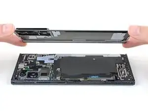
Introduction

Use this guide to remove or replace the USB-C port on your Samsung Galaxy Note20 Ultra.

For your safety, discharge the battery below 25% before disassembling your phone. This reduces the risk of a dangerous thermal event if the battery is accidentally damaged during the repair. If your battery is swollen, take appropriate precautions.

  1. HXAPSS5X3NKEZBXt
    • Completely power off your phone before you begin disassembly.

    • Heat an iOpener and apply it to the left side of the rear cover for one minute.

    • A hair dryer, heat gun, or hot plate may also be used, but be careful not to overheat the phone—the screen and internal battery are susceptible to heat damage.

  2. sZAXBfcgHUTlUQqI
    sZAXBfcgHUTlUQqI
    FVLlMvaVCj1pDZkj
    E2VJIZiHj4JfjOlO
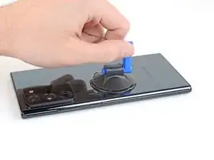
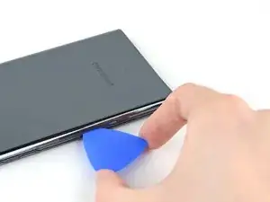
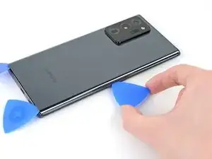
    • Apply a suction cup to the heated edge of the rear cover, as close to the edge as possible.

    • If your back glass is badly cracked, covering it with a layer of clear packing tape may allow the suction cup to adhere. Alternatively, very strong tape may be used instead of the suction cup. If all else fails, you can superglue the suction cup to the broken panel.

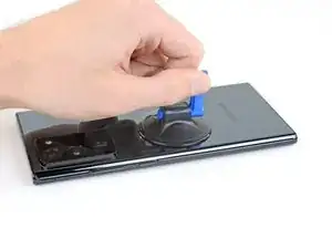
    • Pull up on the suction cup with strong, steady force to create a gap between the rear cover and the frame.

    • Depending on the age of your phone, this may be difficult. If you are having trouble, apply more heat to the edge and try again.

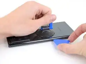
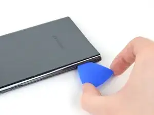
    • Insert an opening pick into the gap.

    • Don't insert the opening pick more than 5 mm into the phone or you risk damaging the internal components.

    Great guide! Much appreciated! I've opened the phone twice now due to not gluing enough the first time. I wish iFixit sold a battery for the N20 Ultra. I had to get generics and one was total garbage.

    Steven Roberts -

  3. i4MiyCCamyw4J6SX
    i4MiyCCamyw4J6SX
    PyL1BkDZpEcnuoJL
    OXNO1MSnlT5KSdaU
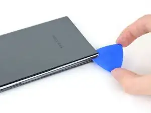
    • Slide the opening pick along the left edge towards the bottom left corner to cut through the adhesive.

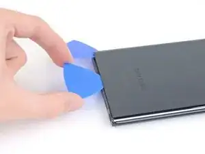
    • Leave the pick inserted in the bottom left corner to prevent the adhesive from re-sealing.

  4. uqcTEBomZhSKHwVa
    uqcTEBomZhSKHwVa
    FgJCRcyEKTiATQc2
    RCFRW3IgnVORkZal
    • While cutting through the adhesive, don't insert the opening pick more than 5 mm into the phone or you risk damaging the internal components.

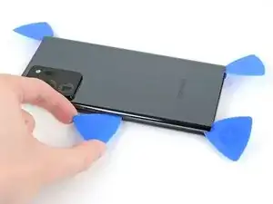
    • Repeat the process of heating and cutting the adhesive along the three remaining sides of the rear cover.

    • You can insert each new opening pick in the gaps created by the opening picks left in each corner.

    • As you proceed, leave an opening pick in each corner to prevent the adhesive from re-sealing.

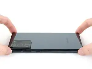
    • Slide an opening pick back and forth around the entire perimeter of the phone to release any missed adhesive. Reheat any stubborn adhesive.

    A que temperatura debe calentarse el teléfono para retirar la tapa trasera?

    Carlos Lozano -

  5. AKihICedkRISIPMh
    AKihICedkRISIPMh
    KFgU1GoqHt3Z4ZT5
    • Lift the rear cover straight up to remove it.

  6. ERcpeA35onq5S6KC
    ERcpeA35onq5S6KC
    RG1ZOBNc4LCTMbnK
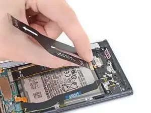
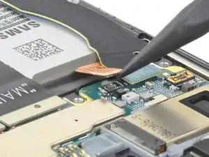
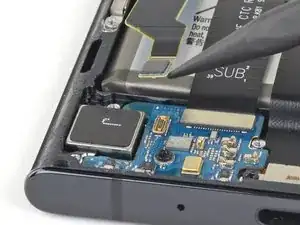
    • Use the pointed end of a spudger to pry up and disconnect the wireless charging coil press connector.

    • Take care to pry only under the edge of the connector to prevent damaging the socket itself and surrounding components.

    • To re-attach press connectors like this one, carefully align and press down on one side until it clicks into place, then repeat on the other side. Do not press down on the middle. If the connector is misaligned, the pins can bend, causing permanent damage.

  7. WIDFM5KZp1SyJTQG
    WIDFM5KZp1SyJTQG
    W5CBgNKsB1Cpx3fG
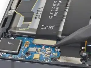
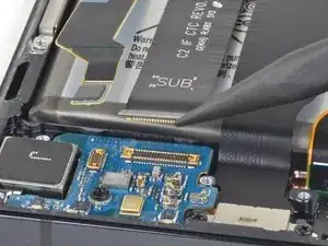
    • Use the pointed end of a spudger to pry up and disconnect the white press connector located in the bottom right of the motherboard shield.

    can i buy the motherboard shield

    Chu Lawrence -

  8. VNtPrwCeJxJNgxtI
    • Use a Phillips screwdriver to remove the six 4.0 mm screws securing the motherboard shield.

    • If these screws have not been removed before, they may be difficult to remove as they have threadlocker on their threads.

    • Throughout this repair, keep track of each screw and make sure it goes back exactly where it came from.

  9. bmNGGoKHADitLVy1
    bmNGGoKHADitLVy1
    VVGpALAwkZPGvmOq
    HTlScxHeVQdQARxQ
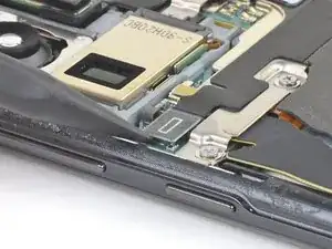
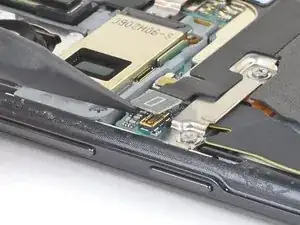
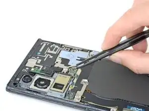
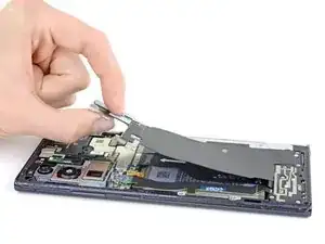
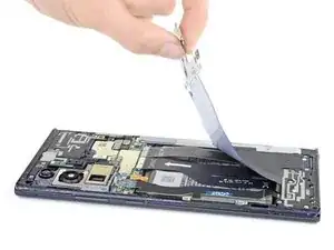
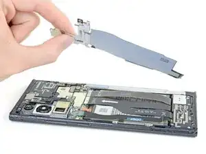
    • Use a pair of tweezers to lift up the motherboard shield.

    • Be careful when handling the motherboard shield because its edges are thin and sharp.

    • Use your fingers to grip the motherboard shield.

  10. 5iZgnw5Poyyj4NRf
    5iZgnw5Poyyj4NRf
    GcMOZZcHNpOmTo5c
    AxBEytFHMcyGj1DN
    • Peel the wireless charging coil up and away from the device to remove it.

    • The wireless charging coil is secured to the device with light adhesive.

  11. Iqs24GcpWAEUUMoO
    Iqs24GcpWAEUUMoO
    Y1GeRURJ2BnyFZbQ
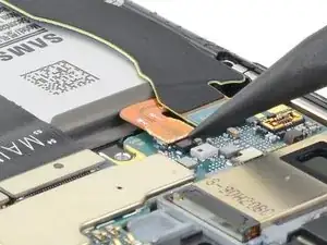
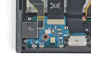
    • Use the pointed end of a spudger to pry up the battery press connector to safely disconnect the battery before continuing repairs.

  12. hDorxaKEAxdEgQqQ
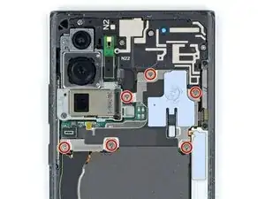
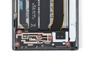
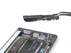
    • Use a Phillips screwdriver to remove the five 4.0 mm screws securing the loudspeaker to the frame.

  13. TyZGPJd5gHrORR2m
    TyZGPJd5gHrORR2m
    MSIyJowgTWiXPyc4
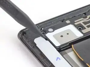
    • Insert the pointed end of a spudger into the hole marked by a triangle on the left side of the loudspeaker.

    • Use the spudger to pry up and loosen the left side of the loudspeaker.

  14. MyLSyqTyxbHyhyIr
    MyLSyqTyxbHyhyIr
    IQlHPpF3DXHlJRju
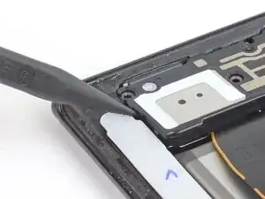
    • Insert the pointed end of a spudger into the hole marked by a triangle on the right side of the loudspeaker.

    • Use the spudger to pry up and detach the loudspeaker from the frame.

    • The loudspeaker is secured to the frame by clips along its bottom edge.

  15. CDgIYsYgeGNUx3ZQ
    • Use a pair of tweezers to lift and remove the loudspeaker.

  16. MaGLMomfNlCQ132f
    MaGLMomfNlCQ132f
    dc1ChKbGNHyXBICH
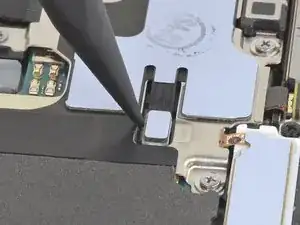
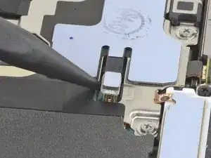
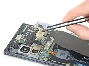
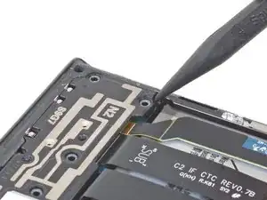
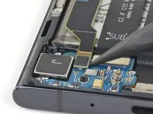
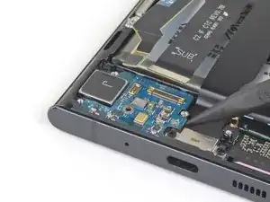
    • Use the pointed end of a spudger to disconnect the secondary interconnect cable from the daughterboard.

  17. yVACo1yTpm4IIlKR
    yVACo1yTpm4IIlKR
    vBVqgvvrVdhPyCLQ
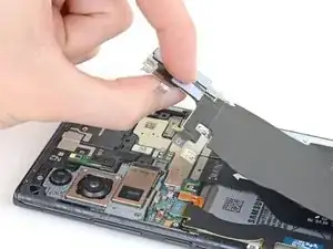
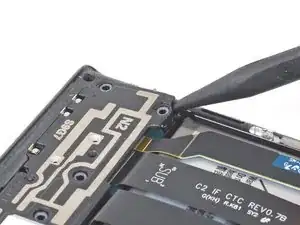
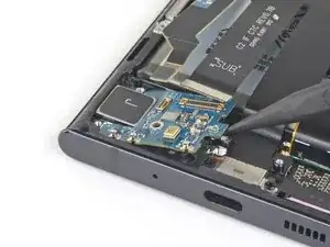
    • Use the pointed end of a spudger to disconnect the main interconnect cable from the daughterboard.

  18. tJtkkpcn5W4QGZcX
    • Use a Phillips screwdriver to remove the 3.0 mm screw securing the daughterboard to the frame.

  19. ZBthUsYIA1jiGin6
    ZBthUsYIA1jiGin6
    45cxF1sNLiDIpBuj
    • The daughterboard is fitted to the frame by three spring connectors along its bottom edge.

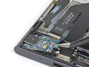
    • Insert the pointed end of a spudger under the right side of the daughterboard near the screw boss.

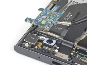
    • Use the spudger to pry up and detach the daughterboard from the frame.

    • There are small surface-mounted components underneath the daughterboard. Only insert the spudger as far as necessary to avoid damaging the components.

  20. IlLdVBsfP4QtACyi
    IlLdVBsfP4QtACyi
    i5JW61dag5qMLxjs
    • Use a pair of tweezers to lift and remove the daughterboard.

  21. uuAZVACbvEAYW3If
    uuAZVACbvEAYW3If
    eAHcGoy6Uf3WFQxA
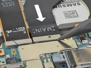
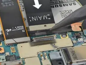
    • Use the pointed end of a spudger to disconnect the main interconnect cable from the motherboard.

  22. sIIZAKw1RW3wK5FO
    • Use a Phillips screwdriver to remove the two 3.0 mm screws securing the USB-C port to the phone.

  23. HwjjgfMaVSypmVxW
    HwjjgfMaVSypmVxW
    hQpK6N5aSLlPZ1xs
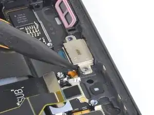
    • Insert the pointed end of a spudger under the left side screw hole on the USB-C port.

    • Pry up the USB-C port to loosen it from the frame.

    • The USB-C port may fling out of its slot while it is being pried.

    • Avoid scratching the USB-C port's copper pad with your pry tool.

    • The USB-C port is held in place by a red rubber gasket. Prying up with a steady force will gradually loosen the USB-C port from its slot.

  24. Gb5amVPpV6PtYxcD
    Gb5amVPpV6PtYxcD
    aMXqLdxBmCDeRIPr
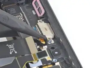
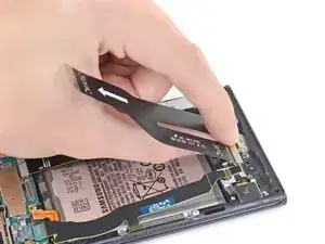
    • Grip the USB-C ribbon cable with your fingers close to the USB-C port.

    • Remove the USB-C port by pulling it up and away from the bottom of the phone.

    • Avoid bending the ribbon cable more than necessary to prevent damage.

Conclusion

Compare your new replacement part to the original part—you may need to transfer remaining components or remove adhesive backings from the new part before installing.

To reassemble your device, follow these instructions in reverse order.

Take your e-waste to an R2 or e-Stewards certified recycler.

Repair didn’t go as planned? Try some basic troubleshooting, or ask our Samsung Galaxy Note20 Ultra Answers community for help.

Kyle Smith

Member since: 01/02/21

40669 Reputation

3 comments

I would like to also add to this tutorial for the last step after you remove the USB-C Charging port and once you reinstall the port, rather its a new one or the same stock oem port that you took out. You should be extremely cautious to how tight you tighten these screws as the LED Touch Display actually lays flat against the frame and if you over tighten these screws that hold this port down, you will figure out quite easily that 1. the screens are very fragile and 2. these screws are able to be tightened and will not stop causing unwanted pressure onto the screen and will destroy the screen which will make it useless as the phone will work just without a display or touch interactions with the phone until buying a new display to replace it.

Jay -

Big rule of thumb for smartphones, tighten only until it feels snug, don't crank things as tightly as they can go. This was also a problem for iPhone repair, some were cranking as tight as possible and killing their screens. The screws have loctite, they're not going anywhere.

Zack is Back -

This is an excellent article! Many Thanks For Sharing

GBENGA JOSHUA BOLARINWA -