Introduction

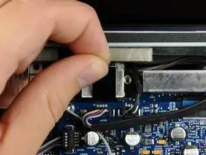
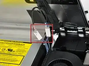
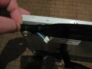
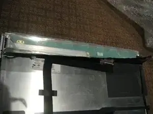
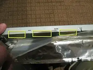
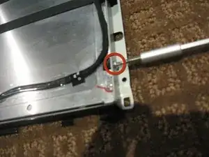
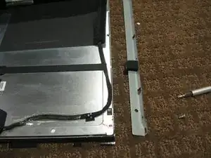
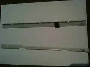
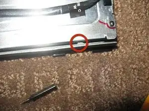
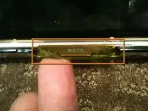
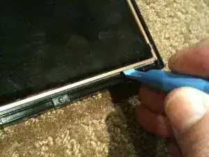
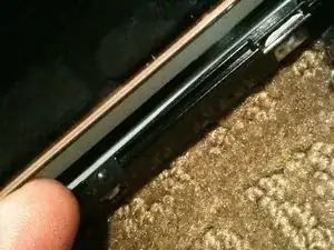
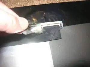
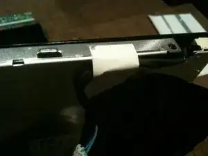
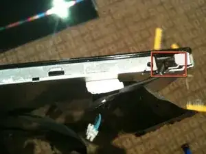
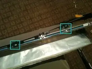
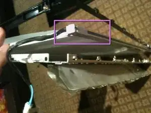
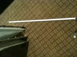
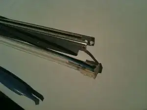
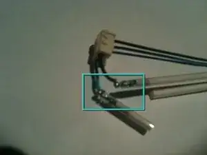
This guide will show you how to remove the CCFL tubes from the CCFL assembly.

  1. 3BdxtI2HvAvYfdgY
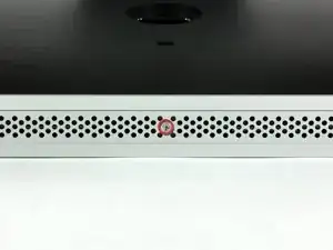
    • Loosen the single Phillips screw in the center of the access door.

    • This screw is captive in the access door.

    • Remove the access door from your iMac.

    isn't it actually pc2-5300s ?

    grze -

    It is for the 2133, the 2210 uses 6400

    maccentric -

    There are comments elsewhere in this step by step re. the bezel removal. That step does NOT show how to remove it. Well, take the 5:39 secs to watch the above video. It clearly shows how the aluminum framed bezel easily comes off once you've seen it done. To whoever decided to preface these instructions with that video, thank you.

    ECJohansen -

  2. hE55xqsxNSJoZGy1
    hE55xqsxNSJoZGy1
    jM2sVKYNECL1jHNQ
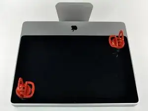
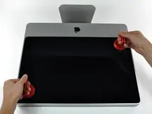
    • The glass panel is fixed onto the front bezel with fourteen magnets around its perimeter.

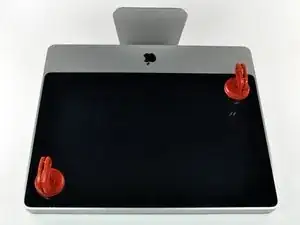
    • Stick two suction cups to opposing corners of the glass panel.

    • To attach the suction cups we sell, first position the suction cup with the movable handle parallel to the face of the glass panel. While lightly holding the suction cup against the glass, raise the movable handle until it is parallel with the other handle.

    • If your suction cups refuse to stick, try cleaning both the glass panel and the suction cup with a mild solvent such as Windex.

    At this stage and later handling the LCD I found thin cotton gloves helped to reduce smudges

    john31 -

    My GPS unit's car mount suction cup worked nicely here - couldn't find any at the store and didn't want to wait for mail order!

    Two cups would make it easier but one is fine if you place it in the center and are careful to pull the panel straight out.

    Mathew Hendry -

    Why use suction cups when some finger nails will do the job nicely, though a plastic spudger might work too. Start at a top corner. Prize the glass away from the case and leave finger nails in. Move the other hand along the top edge and then with finger spread peel the screen cover away. Be careful not to twist plastic I suppose, but I've had no difficulties.

    damianwise -

    3M Command Strip hooks in opposite corners is another fabulous option when suction cups are not available!

    Adam McCombs -

    Tape works fine, here. Search for a YouTube video for a simple look-see.

    Richard -

    I didn't have any suction cups, but my pencil sharpener (the kind that suctions to the table) worked great. I put it on the middle and lifted straight up.

    Lisa Mac -

    For a quick 'n' dirty alternative "tool" for this step, take a look at IKEA's Stugvik suction hooks: they provide an excellent adjustable grip. Just used it to take apart an EMC2133. Cheers!

    hadderakk -

    Suction cups usually available at Home Depot or Lowes, in the flooring section. (They're used to handle large ceramic & stone floor tiles.)

    Griff in Fairbanks -

    I can confirm it is fairly easy to pull it up, the heavy duty suction cups were adequate of course, but pretty sure you can do it without heavy duty stuff? Panel is rather light too.

    Julien -

  3. brspUaXYZhvWBhIu
    • Gently pull the glass panel straight up off the iMac.

    • The glass panel has several positioning pins around its perimeter. To avoid shearing these pins off the glass panel, be sure to only pull straight up during removal.

    • Be meticulous about cleaning the LCD and the inside face of the glass panel before reinstallation, as any fingerprints or dust trapped inside will be annoyingly visible when the display is on. Placing the glass flat, inside face down, on a fresh aluminum-foil surface is a good way to keep it clean.

    In order to avoid unnecessary smudges and what not I covered the LCD itself with some plastic wrap while doing the hard drive upgrade. When I reinstalled it all I needed to do was blow off a few dust particles.

    robgendreau -

    While you are at it, it is worth cleaning out dust within the case to help with cooling - particularly around the fans and vents.

    For the screen I used a lens cleaner from my camera bag. These have very fine fibers and won't leave detritus.

    Mathew Hendry -

    Note that the front glass panel is quite light. When reassembling I found it impossible to get the LCD free of dust with the computer lying on its back. I had success with standing the computer up, tilting the LCD down as far as it goes, holding the glass panel upright in front of the computer (about 1 foot away), lightly spraying both the LCD and the back side of the glass panel with compressed air, and then attaching the glass panel (with the computer upright). It took me 5 tries before it was completely clean of dust once the front glass was on.

    axel -

    Although I do not advise it, you can substitute the suction cups with two strips of duct tape along the sides of the glass, with the tape attached to it's self in the middle of the strip

    Erin -

    Tuandomino ini sudah di akui oleh para member member setia di dunia situs poker online Indonesia. Yang pertama situs ini sudah diakui dan mendapatkan sertifikat resmi oleh pusat server situs poker online.

    tuansakong99 -

    Get out of here with your spam.

    Jason Zak -

  4. CNBFg1PCLDsLDteG
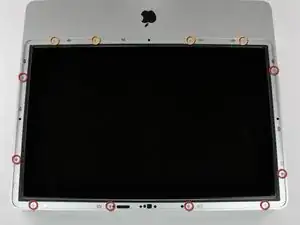
    • Remove the following 12 screws securing the front bezel to the rear case:

    • Eight 13 mm T8 Torx.

    • Four 25 mm T8 Torx.

    On the 24" EMC2134 there are 3 screw sizes: 6x13, 4x20 & 2x30mm, particular note should be made of their location.

    john31 -

    Note for the less experienced.. the case is plastic and the metal coarse thread screws will easily cut a new thread in the hole if you don't line up the screw in the original thread. Do this a few times and the hole will be stripped and the screw no longer tightens.

    TIP:- place the screw in the hole and rotate BACKWARDS/counter clockwise (for RH threads) until you hear/feel it click/drop into the original thread then tighten the screw down. rotate it a couple times to get the feel of things. If there is any significant resistance you probably don't have the original thread.

    This trick also works on the fine metal thread screws and can help avoid cross threading them.

    HIH

    Richdave -

    On the 24 inch iMac Model A1225 EMC #2134, the two T8 Torx screws in the middle are the longer of the four total bottom 25 mm screws. Just a note for reassembly.

    bhoffs -

    This step is not really explained here with pictures. But you can check this same step in another guide to help you : iMac Intel 20" EMC 2266 Front Bezel Replacement

    thibault -

    I'll echo Thibault's comment. This guide does not actually tell you when and/or how to remove the bezel! Click on the other guide he linked to see the photo and instructions.

    steven -

    Make sure you're ram slot at the bottom is open to remove front frame bezel

    edgain99 -

    I think you're missing this step: With the iMac lying on its back screen facing up, grasp the aluminum sides of the bezel and carefully pull it straight up. Then disconnect the microphone cable. Took me a while to figure it out.

    Richard Cacciato -

    I found it helpful to use a few lids from spaghetti sauce jars to hold the different screws. I used a sharpie to mark the inside of the lid w/ location taken from or the step number from directions. Then I placed a small magnet under the lid to hold the screws inside the lid in case I accidentally jostle something on the table. Worked great! You can also use a magnetic knife bar to line up the lids in sequential for the project.

    tom -

    I cut a hardwood block and drew the outline of the the iMac shape with the base as key. I then drew another two lines at 1/2” and 1” all around from the outline. This done I drilled holes for each screw (12 Outer securing the front bezel to the rear case , and 8 Inner screws securing the display panel to the rear case ). That way I don’t lose any or get them mixed up.

    jmadams -

    I think the title of this chapter could be (in french) désinstallation but not Installation with is the contrary. Idem for the other chapters.

    Bertrand Guigaz -

  5. BqQQYMTGV1Fgadp1
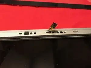
    • Place your hands at the top corners of the bezel (to the side) and lift the bezel 2-3cm from the body by working from the top. After this you can also disengage the bottom of the bezel (the memory modules will prevent the bottom of the bezel to detach first). When reassembling, start with the bottom of the bezel.

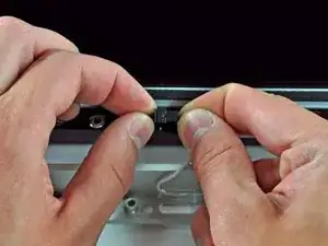
    • The top of the bezel hosts a microphone attached to the logic board. Gently lift the bezel to not damage the microphone wiring or connector by accidentally pulling the cable.

    • At this point, you can either detach the microphone cable and remove the bezel, or keep the microphone cable attached and rest the bezel on your work surface or the chassis of the Mac.

    • To fully detach the bezel: disconnect the microphone cable connector, removing tape as necessary.

    • To keep it attached, leave the microphone cable attached to the logic board, and place the bezel 'above' the chassis, with the microphone cable forming a hinge.

    • If you keep the microphone attached to the chassis, make sure you don't accidentally damage the microphone or logic board by bumping into the loose bezel.

    I avoided this step by just flipping the housing over and having it lay flat on the table. The tape on mine was on really tight, and I risking ripping the wires out of the connector if I messed with it (I didn't have some really small scissors which might have helped removing it). I would suggest either securing the body of the iMac and the housing to the table you're working on, or somehow securing the housing to the body, so that it doesn't move around accidentally, since it's only hanging on by a very thin wire at that point.

    robgendreau -

    ^^^ This! This tutorial should be amended for this step. Much, much easier and less damage-prone.

    (There really oughta be a step addressing the removal of the bezel as well.)

    cklarson -

    Make sure you do not pull this apart by the wires. Have a firm grasp on the plastic parts. Do not force back together. It only goes back together one way. Also, it is crucial when placing the aluminum bezel back in place that this wire is out of the way. It often gets in the way and is easily damaged.

    Kyle Freeman -

    CAUTION - To disconnect the cable, you'll need to support the bezel while you carefully extract slack microphone cable which is tightly tucked within the iMac. (I didn't have this guide's 'notes on' and missed robgendreau's warning - then inadvertently shifted the bezel and busted my microphone cable in this step.)

    dagnew -

    Don't forget to pull the microphone cord out before you put the panel back on. Otherwise you will have to go back and remove screws to find that microphone cord

    Melvin Hines -

    As robgendreau says, avoid this whole step by opening the bezel and laying it upside down above the iMac, still connected by the mic cord, just carefully. Then replace the battery, suck/blow out your dust, and carefully rotate the front bezel back over the iMac from where you removed it. No cord manipulation or damage at all!

    recmsoj -

    When reassembling the bezel, you should actually gently pull the microphone connector (and cables) through the ~1 inch long slot in the bezel next to the iSight camera, when lowering the top part of the bezel onto the chassis . Then further lower the bezel onto the chassis of the iMac, while making sure there’s no room / play between the bottom of the bezel and the bottom of the body (where the memory slots reside). . This way you’ll avoid damaging the microphone cable. Finally gently push the microphone wires and connector through that sale long slot in the bezel to conceal them inside the bezel.

    Olivier Biot -

    Tuandomino merupakan Situs Poker Online dan qiu qiu online yang terbaik di indonesia dengan halaman mobile friendly , serta sangat ringan untuk dapat kalian akses melalui pc atau pun gadget.

    tuansakong99 -

    How about no?

    Jason Zak -

    The tutorial video is great, but they were fortunate to have such a long microphone cable to work with. The iMac I just upgraded had a cable on the system side (not the one on the bezel) that is barely long enough to provide enough play to be able to grasp the connectors when re-attaching them.

    Disconnecting the microphone cable is done automatically, when you breathe on it. Or look at it. Or reattach the bezel and get it screwed down.

    However, it should be noted that this connector is a LUXURY compared to the first-gen ("polycarbonate") Intel iMacs. Those come configured with the auto-slice microphone cable: the cable simply shears off during disassembly of the case.

    Boyd Waters -

  6. cn4DSRRECAdL62PQ
    cn4DSRRECAdL62PQ
    6eLmQgdJvqsCJnM2
    • When reassembling the bezel:

    • be sure to tuck the microphone cable and connector into the void next to the camera board.

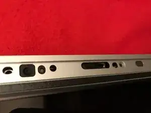
    • Gently guide the microphone connector and cables through the ±1in long slot at the right of the iSight camera. Once the bezel is properly assembled, gently push the microphone connector and cable into the bezel through that slot.

  7. JWngD11hCSPCuDPR
    JWngD11hCSPCuDPR
    HwPWZVxEaGVoSwh1
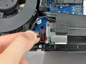
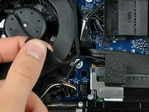
    • Pull the LCD temperature sensor connector straight up out of its socket on the logic board.

    • If necessary, de-route the LCD temperature sensor cable from behind the logic board.

    • When you remove the LCD, check the routing of the LCD temperature display cable. On reinstalling the display, be sure this cable does not block one of the bottom screws for the front bezel.

    This was the most confusing step, because the video shows MJ just tilting the monitor open, and I had a ribbon cable hooked up to it. Finally figured out that the ribbon cable was connected to the LCD temp sensor cable, and it was neatly tucked under the adjacent fan. Had to pull it pretty hard to get it out from under the fan, and then could tilt the LCD. Instructions are not completely clear about this, only that you may have to reroute the cable around the motherboard.

    d3nn151950 -

    I agree, there is no sign of how to remove the bezel (it took me several minutes to understand it was even the bezel that came off here) in these steps (in all the guides for this model, in fact). On step 4 says remove the LCD screws, and suddenly step 6 shows innards and fans etc - !! - What about showing the bezel being removed here - super confusing and not up to usual ifixit high standards.

    hutchwilco -

    If you rush through the reassembly, it's very easy to miss reconnecting the LCD Temp Display cable. I just did it and one of the fans came on full-speed and stayed there through a new macOS install. Did a Google search and found mention of this symptom. At first I was thinking I switched one or more of the inverter cables but this guide shows that this is not a problem. Once I reviewed this step, the problem was obvious as was the solution. Thanks again, iFixit, for saving my nappy behind.

    barryjaylevine -

    I can speak from experience, this cable’s a pain. It came out of where I tucked it and snuck behind one of the bottom screws, which pierced it during reassembly, afterward it would not boot properly. It’ll boot without the cable plugged in, but the fan runs near max. I’m glad it can at least be used while I wait for the replacement cable to ship. What a weird (lazy) design choice from Apple.

    Ian Sprenkle -

    In case the iMac hasn’t been opened for years (typical situation), then you may want to first carefully and prudently remove the piled up dust with a vacuum cleaner and a soft brush. Definitely not with a can of compressed air, as then you’ll spill the debris everywhere (and on the display). Otherwise you won’t be able to get hold of the right cable, connector or screw. In addition, it will help increase the air flow hence reduce heat (and allow the fans to operate at a lower speed).

    Olivier Biot -

    hi could some one help me with this cable replacing as it has been damaged i mean i would like to know if i could repair the wire or simply replace it and also what type of wire i would need and how could i find one please i m new thanks

    kazi

    suhrab kazi -

  8. tDNoZU1Z1bcqbNDP
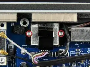
    • Remove the two 5.3 mm T6 Torx screws securing the data display cable to the logic board.

    My Torx 6 driver purchased from ifixit didn't fit the screws well and potentially would strip them. Had to purchase a better driver to fit better in order to loosen these screws.

    kakisback -

    reinstalling these screws requires extra care to be sure you don't drop it and loose it under any of the other components.

    kakisback -

    Make sure not to drop the screws.

    ulan -

    Removing these screws was the most difficult part of the whole job. They were tight and felt as if the heads were about to chew up. I had to press really hard and jerk the screwdriver counter clockwise to loosen them. Despite others' warnings, I managed to drop a screw when reinserting.

    kevinp -

    The only tool I needed to buy was the T6 Star Bit - the first auto store I went to had it. These screws are tiny so you have to be careful not to drop them!

    James Miles -

    When reinstalling these tiny screws, consider placing the iMac upright. That way when you (inevitably) drop these tiny screws, you don't lose them in the guts of the computer where they are likely to fall into a fan.

    stown1211 -

    Yes, this step is very difficult. I finally used a magnet to magnetize the torx driver, and that helped immensely...however, that was AFTER I lost the right one inside the computer. You really only need one screw to reattach the monitor connector, however.

    d3nn151950 -

    Argh! I dropped my right screw into the bowels of the iMac. I can't find it anywhere and am loath to leave it rattling around as well as to tear down the machine any further.

    steven macfarlane -

    Well, I followed the instructions for right-speaker removal and optical drive fan removal and still couldn't find the right screw. I couldn't hear it rattle either so figured it was wedged somewhere. Using an inspection mirror and flashlight, I finally found it. It had fallen down and wedged between the PCB and the plastic housing (below the ports). I was able to slide it toward the right until it came to the void left by the right speaker where it fell out into my hand.

    steven macfarlane -

    It's true, these were super tight. I only had a T5 which worked on the first screw, but the second wouldn't budge. Ended up filing the tip off the T5 bit - presto! - instant T6.

    marcintosh -

    I Think the real screw size is 3.5 mm T6 Torx, not 5.3 mm

    raul -

    Dropped those little bastards like 2-3 times into the deeps of my iMac. The right one is really tricky. If you drop it: better get yourself very thin tweezers and gently shake your mac. :(

    Popelnase -

    Note that just below where you are working is the PRAM battery. If you have never replaced this, now is a good time so you won't have to open the machine up again in the near future. The battery is a CR2032.

    mattgauntt -

    Taking all the warnings into account about losing these tiny screws, during removal and replacement I held onto the screws tightly with a very fine needle nose tweezer. Fortunately I managed not to lose them either out or in. I highly recommend using a small gripper during this step.

    recmsoj -

    While you have the case open this would be a good time to replace the PRAM battery and carefully clean the fan and interior of the case with Q-tips / compressed air.

    John Fisk -

    These screws are Torx 7 - at least that was what

    I used on them and got a prefect tight fit ... .

    Patrik Albin -

    torx 6 didn't do it, needed torx 7

    nielsdolieslager -

    Torx7 did NOT work for me. Torx6 did.

    pdienstm -

    If you do manage to lose one of these screws, will the cable still be held in properly if you reinstall it with only one?

    Peter Wood -

    Advice / 2 cents : Unscrew/screw with the iMac vertical/propped up and a magnetized screwdriver. Should be no issue. If it falls, it will fall on your desk, not behind stuff on the back of the iMac. You could even put iFixit magnetized mat underneath for added safety :)

    Julien -

  9. ScwTYOXWNchMMunI
    • Use the attached black tab to pull the data display cable connector away from the logic board.

  10. cTxvnfEYYGKFQlOv
    cTxvnfEYYGKFQlOv
    bF6yYqrpjGENW4dW
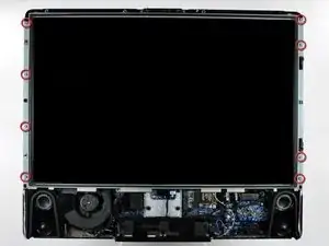
    • Remove the eight 12 mm T8 Torx screws securing the display panel to the rear case.

    • Depending on the age of your driver, a T9 Torx bit may fit better.

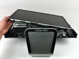
    • Lift the display panel from its left edge and rotate it toward the right edge of the iMac.

    I was able to disconnect the two connectors to the front easily. With those off, I just rotated the LCD out of the way to expose the hard drive. Again, make sure it's stabilized if you do this so that when you yank on something else you don't send it flying.

    robgendreau -

    I did a HD replacement on my 24 inch iMac. It's basically the same, but it does not have disconnectable invertercables. Instead, there's just one cable that's can't be disconnected. It sits too tight to rotate the display to the degree that you can lean it against something, so the only way to get the job done was to call in an extra set of hands to hold the display while I took out the hard drive.

    Marijn -

    On the 2134 model, I found that the LCD must be lifted from the RIGHT (not the left as per the 2133 guide) - the connector wires are covered in nylon housing and it's way easier just having someone hold the LCD vertical whilst you replace the HDD, unless you have small fingers and feel like disconnecting completely ...

    simon -

    During reassembly, make sure that the data and temperature cables will reach their sockets before inserting the eight screws.

    kevinp -

  11. jlNvyVu6OqYBg1HL
    jlNvyVu6OqYBg1HL
    3cub2cQRMlHxbNBv
    • With the display panel still lifted, disconnect the four inverter cables.

    • During reinstallation, place the four inverter cable connectors in voids between components attached to the rear panel so the display panel will sit flush.

    • During reassembly, the order of the inverter cables is interchangeable within each socket.

    • If you are replacing a hard drive and have an extra set of hands, it is possible to reach in and remove the drive without disconnecting anything but the LCD temp and display connector in the previous step with the LCD in its propped position.

    Make sure to not squeeze the inverter-cables between the superdrive and the display when putting the display back on !

    epzzky -

    This was the only step different for my 2134 - it is just one cable that connects to the monitor - disconnect the monitor end rather than the motherboard side.

    Jim Laredo -

    There is no need to discnnect the inverter cables if display is positioned against a wall or something of the sort. Make sure it doesn't tumble over !!!

    info5825 -

    For 24" iMacs, a single power cable is attached on the left side of the screen. To remove the cable, lift the screen from the right side and rotate it to the left. Remove the black plastic protector on the back of the screen and disconnect the cable.

    Matt Stichnoth -

    Make sure you squeeze the two ends of the inverter cable together firmly - if not you will get yellow areas on your screen. One of my cables had not quite been clicked together, and I had to unscrew everything all over again.

    Philip -

    So does it matter which ones are connected to which?

    That is, at each end there are two connectors (one pink/black the other light blue/dark blue on the "male" side). The "female side appear identical. Does it matter if the pink/black "male" one is connected to the wrong "female" one?

    Mark Gibson -

    Mark, did you ever get an answer about the connectors?

    Mike -

    Agreed this is an unspecified issue and i'm surprised it's not covered? Did everyone else just guess?

    kainatticus -

    Yes, mark each female end in a way that distinguishes itself from the other. I put “P” on the harnesses with the pink wires and “B” on the harnesses with the blue wires.

    steven -

    So let’s say hypothetically I didn’t label them as I failed to notice that they were identical before disconnection. What should I do to resolve this issue?

    Christian Moore -

    Managed to avoid this step just lifting the lcd panel and holding it with my... head ;)

    Antonio Bernardini -

    Yes, I agree. If you just prop the panel up on the left (carefully!) with your head, or as I used a box, or get a friend to hold it up, this step can be bypassed. It is a tight squeeze inside to work with getting the HD in and out but its totally do-able. If using an SSD, which of course you should, you can just tape it down inside, as they weigh almost nothing.

    Jed Weaver -

    I'm trying to find some information on replacing the power supply temperature sensor cable. Mine broke during removal of a bad power supply.

    Mike Overholt -

    Re: Scorps comment above - I got the “beeping” too. Does anyone know how to resolve it, i.e. identify which goes with which? Other than trying every combination?

    mchlgrblsk -

    My screen is just Grey? anyone else have this happen?

    Michael McGuire -

    After replacing iMac’s HDD with a new one I’ve got white screen with vertical black and bluish bands on the left side and two horizontal lines dividing the display into three equal parts (see the image). Any idea what that might be?

    Andrey -

    I tagged the inverter cables with different color sharpies so as to get them connected back the way they were.

    Macrepair SF -

    Step 9…. before I took those tiny screws out for the data display cable on the logic board, I put the tip of the torx tool on a magnet (magnets on the front cover worked fine) for a few minutes. this magnetizes the screws so you are less likely to drop them when you go to put them back in.

    dkkd -

    I replaced the internal hard drive. worked fine. putting everything back together, the CD drive wont insert or eject discs when I tighten the screws on the right side that holds the display in place, or when I put the cover back on. CDs work fine if I leave the screws loose and/or leave the cover off. cant figure out why, i never touched the CD drive at all…

    anyone else have this issue after opening the unit up, and how did u fix it?

    dkkd -

    This happened to me and I found that a cable that had been wrapped around the side of the DVD drive had slid over top of it while I had it open. When I closed it all up, the pressure of the cable against the surface of the DVD drive was enough to impact it. I reopened the machine and pushed the cable back around the side of the DVD drive and it worked fine.

    John Moltz -

    The ‘locking tab’ faces the dot. I placed a label on main body side of the lcd connector with a P =Pink and B =Blue. This way I know to place the connector with the pink on the marked P and blue on the marked B.

    egecko -

    I went with the option of not detaching the screen. I have horror stories around inverters, mostly on notebooks, but still, don’t approach/touch if you don’t have to.

    Ask your wife/somebody to hold the screen while you go through the steps below, without detaching the cables in step 11. It is a couple minute to step 18 and having the drive out.

    Julien -

  12. RrXq3fyvWVdCELPc
    RrXq3fyvWVdCELPc
    DCbXBUq5GvRwT6JI
    dlYQyQAExCFDd3Lc
    • The rest of this procedure should be done in the cleanest possible work environment to avoid dust getting BEHIND the LCD (I learned this the HARD way!)

    • Once the LCD panel is removed you need to peel back the black foil from the top edge of the LCD to reveal the clear plastic PCB protector.

    • Now gently peel the clear plastic PCB protector off the top edge. Make sure you don't damage the flex cables attached to the PBC you are exposing.

    • There are a total of 8 flex cables along the top edge

  13. Ekgfi6ildKcpINwy
    Ekgfi6ildKcpINwy
    iMHY245RvyNN5NGk
    UGl6G2SH2cMNkfME
    • Use a sharpie or similar, mark the side brackets on either side of the LCD panel before removing screws as they are different

    • Use a T10 Torx driver to remove the 2 screws from each side bracket (total 4 screws)

  14. L1IiGarpSqWLfaoc
    L1IiGarpSqWLfaoc
    rRgG4R53dLAl6K6T
    tnsdYXErGTS4HPIr
    • Stand the LCD panel on its TOP edge and locate the lock tabs along the BOTTOM edge. There are 5 along the length of the bottom edge

    • Use a flat blade driver or metal spudger to Gently pop the bezel off the lock tabs.

    • Locate the lock tabs on either side of the LCD panel. There are 2 on each side

    • Use a flat blade driver or metal spudger to Gently pop the bezel off the side lock tabs.

  15. c5ex3xpu3xkhpmgQ
    c5ex3xpu3xkhpmgQ
    jEXsXLlyeaauSBJ5
    cRKnEMqfrRDSRjwk
    • Now gently separate the metal bezel from the main body of the LCD panel

    • Lay the LCD panel down on with viewing side UP and remove the metal bezel

    • Make sure you are careful when removing the bezel from the TOP edge as you will be exposing the 8 flex cables mentioned in step 1.

    • Note the 3 flex tabs on the left edge

    • Do not damage any of the tabs or flex cables as these are the Row and Column Drivers. Damage to these will will cause faults like vertical/horizontal lines or white screen etc.

    • WARNING - Once the bezel is removed the LCD is LOOSE in the black plastic frame - only held in by the small gasket underneath.

  16. q4cTmypHiCL6dfMq
    q4cTmypHiCL6dfMq
    BO1wglCcHxoEDPFe
    • Using a plastic spudger or pry tool, work GENTLY around the edges of the LCD to loosen it from the gasket below - use GREAT CARE so you don't crack or chip the panel as it is only a couple mm thick

    • Once the LCD is loose you need to HOLD it in place in the black plastic frame and GENTLY flip the entire assembly so the LCD is flat on the work surface

    I found on my 2009 20" the LCD stuck fast so left this part out, with the screen facing down on a hard flat surface and continued from the back to get to the ccfl one side at a time to get them out leaving the LCD and backlights assembly together.

    Dan -
  17. MEKleFQSjgrOnRwZ
    MEKleFQSjgrOnRwZ
    oYGPyvdLALWOlFHX
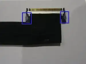
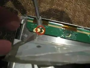
    • Remove the tape securing the LVDS cable

    • Press IN the 2 silver spring loaded catches on either side to release the cable and gently extract it from the connector

  18. 5BNuBer1ol2jUwt6
    5BNuBer1ol2jUwt6
    uhV35w5E1q2jem6H
    • Peel the back Black foil and clear plastic PCB protector to fully expose the PCB that runs across the top of the LCD assembly

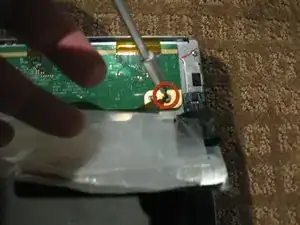
    • Remove the 2ea Philips head screws from each end of the PCB

    • The PCB actually has a 3rd screw hole in the centre of the board. Perhaps my assembly is missing a screw

  19. 1DERto4iWGYemZpL
    1DERto4iWGYemZpL
    MI2PiLnBirhplKVe
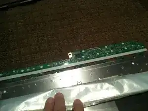
    • Gently flip the PCB over 180deg so it is off the aluminum back panel.

    • Be CAREFUL not to damage the 8 flex cables

    • The PCB may be attached to the aluminium by some adhesive near the LVDS connector. IF so use a plastic pry tool or spudger to GENTLY lift the PCB up

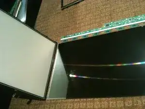
    • Now lift the the back panel off the LCD separating the LCD from the back light assembly

  20. XsAlcNW662QpWdjI
    XsAlcNW662QpWdjI
    GpmViBouCsCsfdLU
    gnJKWNGmHkBpviUY
    • Disassembling the back-light assembly is a little fiddly as there are a number of parts that all want to come apart at the same time

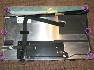
    • Remove the 6 Philips screws from the rear of the back light assembly

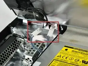
    • Removing the white tape from the CCFL cable.

    • Un-clip the CCFL cable from the black plastic surround

    • There are 2 CCFL cables and the process is essentially the same for each

  21. 61ZuvOQMFJZamMmV
    61ZuvOQMFJZamMmV
    dasEwYxqDL2ZaZ66
    Cp3fwWkjmLhfjB1F
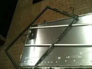
    • Separate the black plastic surround from the aluminum back plate to access the CCFL tube assemblies

    • Start by un-clipping the tabs along the top edge of the assembly. There are 4 tabs along the top

    • The top CCFL tube can be seen and CAREFULLY removed

  22. KMJTOgdjqHLSixZe
    KMJTOgdjqHLSixZe
    vQvAp6pCUVQTIcRu
    Fkrw2OX5qy1Ssvcu
    • The bottom of the black surround can now be un-clipped and the entire surround removed

    • There are 4 tabs along the bottom of the assembly

    • Once the black surround is off the rest pretty much comes apart with the bottom CCFL tube being able to be removed in a similar manner to the top

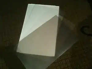
    • The centre of the back light assembly is made up of 4 main parts. A perspex sheet with white plastic coating, 2 opaque matt plastic sheets, and 1 Pearlescent matt plastic sheet

    • The plastic sheets are polarisers so need to be kept clean and free of dust and scratches

  23. 1CWwtG1jf1MfRKRW
    1CWwtG1jf1MfRKRW
    STEhv3qACGwNxBWi
    CTMZv1ER6ATKDQpi
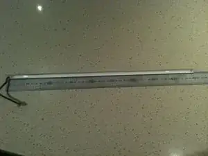
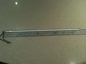
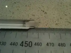
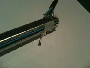
    • The CCLF tube assemblies are made up of a U shaped reflector with 2ea individual tubes inside. The entire assembly is 457mm long and 7.6mm wide. There are no part numbers on the assembly however there is a S on the end with the wires attached and an 18 on the other end.

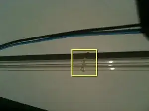
    • The 2 CCFL tubes are held together with a figure 8 rubber band in the middle of the reflector so both tubes must come out at the same time.

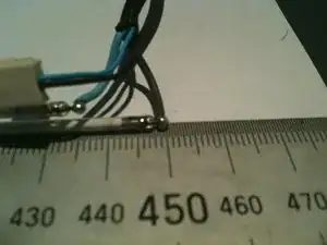
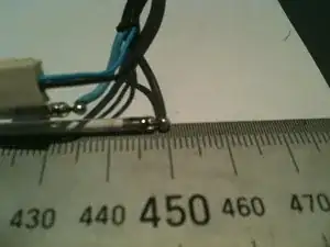
    • The individual tubes are 448mm long (excluding the terminals - standard way to measure is end of glass to end of glass) and are 2.4mm diameter.
    • The CCFL are soldered to the wires so not a simple plug in replacement

    • The CCFL are EXTREMELY fragile so ensure you dont break them when installing them.

    • The CCFL reflectors are a tight fit over the sides of the perspex sheet and the other layers of plastic. Patience and a plastic spudger or pry tool should get you there

    • The closest I can find to my CCFL measurements are either the 446mm x 2.4mm or the 450mm x 2.4mm so I'd suggest the 446mm is used

    • See the Removing CCFL from iMac 20in LCD CCFL assembly guide for details

  24. cY6diaGIl5RoFBSW
    cY6diaGIl5RoFBSW
    jXTTUIKHu6eTASOk
    rumxUqFUvUnXWbFr
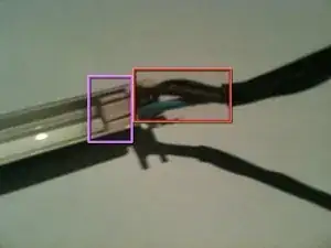
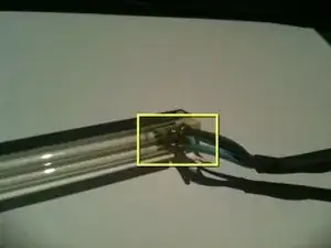
    • Remove the white tape from either end of the rear of the CCFL assembly.

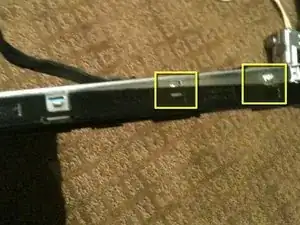
    • Carefully remove about 15-20mm of heat shrink from the CCFL cable to allow the end cap to be removed, making sure you DO NOT cut or nick the wire insulation.

    • The wires have a HIGH VOLTAGE applied during operation and the insulation may break down if damaged causing a short

    • While holding the assembly, slowly and gently pull the THICK wires up and out of the slots in the white rubber cap.

    • Pull the wires one at a time ensuring you don't flex the CCFL and break it.

    • This will reveal the pins and solder joints.

  25. IBWlZlmBSOfn3VoG
    IBWlZlmBSOfn3VoG
    S1YFTMXE5mX1kaDY
    CXeKa1COWBrEm5tY
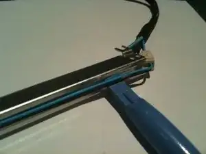
    • Gently push the THIN wires through the rubber end cap to create a bit of a loop on the rear of the assembly.

    • Using a plastic pry tool you can pop the rubber end cap out and then lift the thin wires out of the groove in the rear of the CCFL assembly

    • Note the thin wires are held in the groove by a small amount of adhesive.

    • Run the pry tool the length of the assembly and free the wires all the way to the other end cap

    • gently pop the rubber end cap out of the assembly

  26. rsYRyAXtPinoFPs3
    rsYRyAXtPinoFPs3
    UwyCfO65nIiRtICe
    2jGmN2QLEksASuDl
    • Gently pull the rubber end cap off the CCFL to expose the pins and solder joints

    • The CCFL are FRAGILE and will easily break

    • Now its a simple task of un-soldering each wire and soldering in the new CCFL

    • There is a little figure 8 rubber band tying the 2 CCFL together at their centre.

Conclusion

To reassemble your device, follow these instructions in reverse order.

Richdave

Member since: 10/04/10

32018 Reputation

One comment

Anyone swapped out the ccfl for leds?

Dan -