Introduction
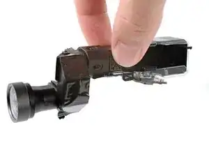
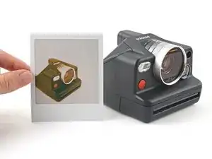
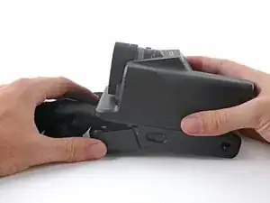
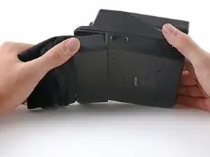
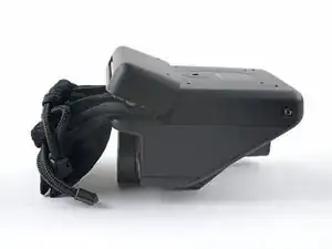
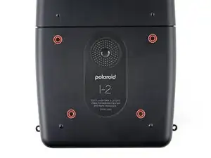
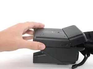
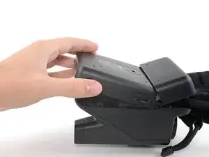
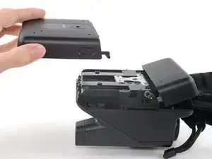
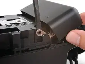
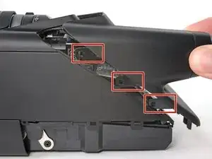
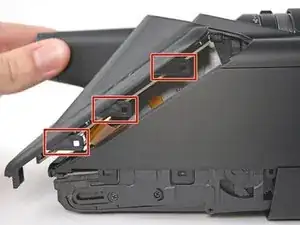
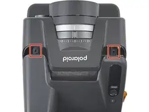
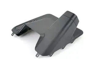
Use this guide to replace a damaged viewfinder in your Polaroid I-2.
If the image in your viewfinder is blurry or nonexistent, you may need to replace your viewfinder.
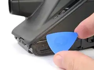
The clips securing the plastic covers are strong and require significant prying. Don't use metal tools to avoid marring the plastic.
This guide requires discharging the flash capacitor to avoid being accidentally shocked during disassembly. Be sure to follow the directions carefully to ensure the capacitor is discharged properly.
Tools
-
-
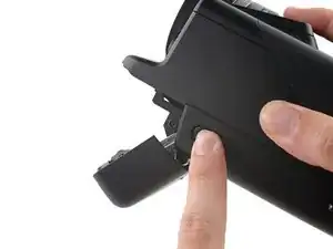
If you have any film left, take some photos and remove the cartridge! Disassembly will expose the film and damage it.
-
Before you begin:
-
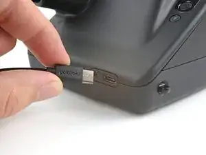
Power down and unplug your camera.
-
Put on the lens cap to avoid scratching your lens during disassembly.
-
-
-
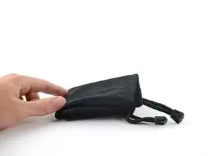
Fold a piece of cloth or napkin (or the included bag) into a small square.
-
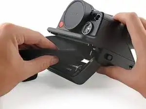
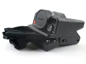
Insert the cloth into the film compartment far enough to block the film door from closing during disassembly.
-
-
-
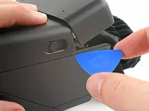
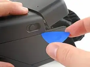
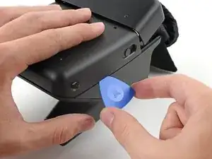
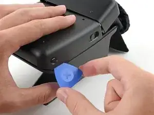
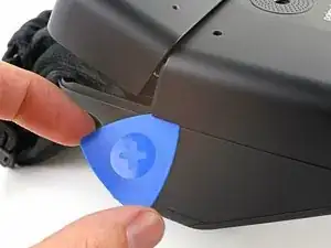
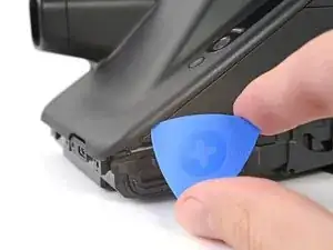
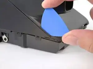
Insert the tip of an opening pick under the top left corner of the bottom cover, near the slider button.
-
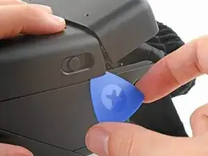
Tilt the pick up and push to position the pick between the bottom and front covers.
-
-
-
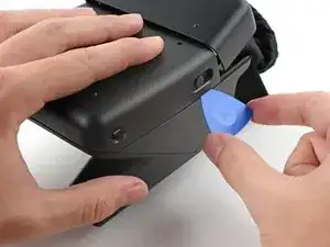
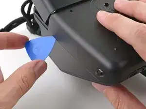
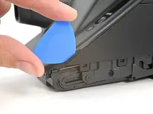
Slide the opening pick toward the rear of the camera to release the clips along the left edge.
-
Leave the opening pick at the bottom left corner to prevent the clips from resecuring.
-
-
-
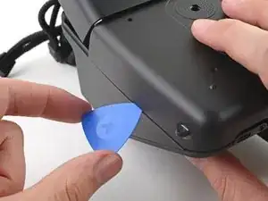
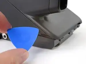
Insert the tip of a second opening pick under the top right corner of the bottom cover.
-
Tilt the pick up and push to position the pick between the bottom and front covers.
-
-
-
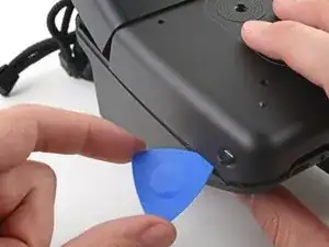
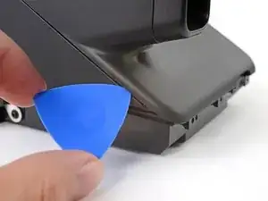
Slide the opening pick toward the rear of the camera to release the clips along the right edge.
-
-
-
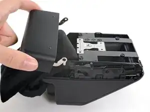
Tilt the back of the bottom cover upward and pull it away from the camera, making sure to thread the film door lever from its recess.
-
Remove the back cover.
-
-
-
Insert the flat end of a spudger between the film door's left hinge and the frame.
-
Twist the spudger to separate the rubber hinge grommet from its peg in the frame.
-
Pull the film door towards the front of the camera to completely disconnect its left hinge.
-
-
-
Tilt the left edge of the film door up to separate the left hinge's rubber grommet.
-
Remove the film door.
-
-
-
Insert a spudger between the frame and the alignment hole on the back cover.
-
Twist the spudger to lift the back cover off of the alignment peg.
-
Repeat for the second alignment peg.
-
-
-
There are eight large clips that secure the back cover. The next four steps show how to release them.
-
-
-
Angle an opening pick upward and insert it at the gap where the bottom right corner of the back cover meets the triangular tip of the front cover’s right edge.
-
Push the pick up to get it above the overhanging lip in the back cover.
-
While pushing upward, slowly rotate the pick towards the left edge of the camera until it's under the front cover.
-
-
-
While pushing the pick downward, slide it all the way up the right edge to release the clips.
-
Leave the pick at the top corner before continuing to prevent the clips from resecuring.
-
-
-
Angle a second opening pick upward and insert it at the gap where the bottom left corner of the back cover meets the triangular tip of the front cover’s left edge.
-
Push the pick up to get it above the overhanging lip in the back cover.
-
While pushing upward, slowly rotate the pick towards the right edge of the camera until it's under the front cover.
-
-
-
While pushing the pick downward, slide it all the way up the left edge to release the remaining clips.
-
-
-
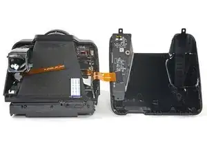
Pull the back cover off the camera and rotate it over the right edge to expose the flex cable.
-
-
-
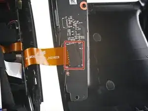
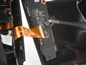
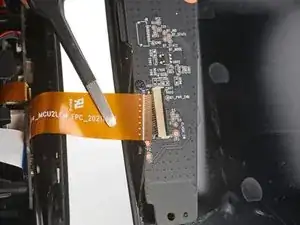
Use tweezers to peel off the tape covering the interconnect cable ZIF connector on the control board.
-
-
-
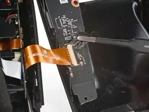
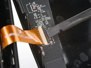
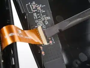
Use the flat end of a spudger to lift up the locking flap on the control board ZIF connector.
-
-
-
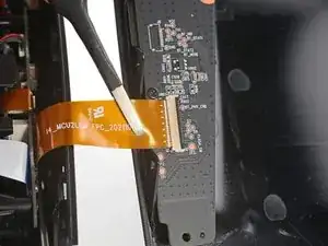
Use tweezers to pull the interconnect cable out of its slot in the control board.
-
Remove the back cover.
-
-
-
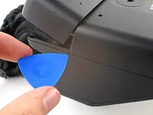
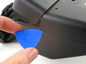
Angle an opening pick upward and insert in the gap at the top right corner of the top cover and front cover, next to the flash.
-
-
-
Slide the opening pick toward the rear of the camera to release the clips along the right edge.
-
Leave the pick in the gap before continuing to prevent the clips from re‑engaging.
-
-
-
Angle a second opening pick upward and insert in the gap at the top left corner of the top cover and front cover.
-
-
-
Slide the opening pick toward the rear of the camera to release the clips along the left edge.
-
Leave the pick in the gap before continuing to prevent the clips from re-engaging.
-
-
-
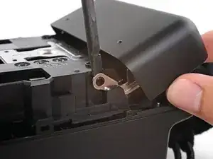
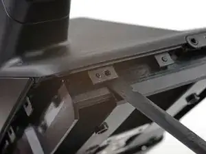
Insert the flat end of a spudger between the frame and the top cover's left external clip, above the viewfinder.
-
Twist the spudger to release the clip.
-
-
-
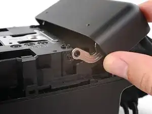
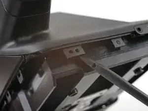
Insert the tip of an opening pick between the frame and the top cover's right external clip.
-
Pry up to release the clip.
-
-
-
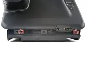
Use a Phillips screwdriver to remove the four screws securing the front cover:
-
Two 5.9 mm-long screws along the back edge of the front cover
-
Flip your camera over.
-
Two 3.9 mm-long screws under the front of the camera
-
-
-
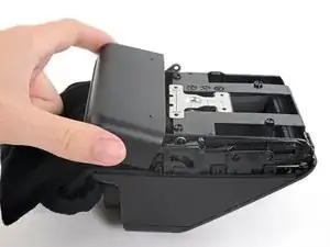
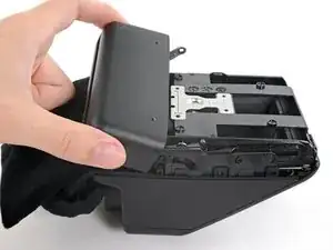
Pull the front cover away from the lens to release the clips along the front edge and slide the viewfinder out of its cutout.
-
-
-
Use tweezers, or your fingers, to push the lidar sensor bracket toward the lidar sensor and off its alignment pegs.
-
Remove the lidar sensor bracket.
-
-
-
Lift the rear of the front cover while pulling the entire cover toward the front of the camera to separate it from its lip under the lens.
-
-
-
Lift the front of the cover over the lens.
-
Slide the front cover toward the rear of the camera until the back edge clears the viewfinder.
-
-
-
Remove the front cover.
-
If you're disassembling further, put the lens cover back on to prevent scratching the lens.
-
-
-
To minimize the risk, make sure to either discharge the capacitor properly before continuing, or wear rubber gloves for added protection.
-
-
-
The battery connector is located on the inside of the main board.
-
Insert the tip of a spudger under the head of the battery connector, where the cables meet the head itself.
-
Pry up to disconnect the battery.
-
-
-
Pull the lidar sensor up and out of its slot in the frame.
-
Rotate the sensor so its exposed board is facing upward and let it hang over its slot.
-
-
-
Use the point of a spudger to "walk" the lidar sensor cable connector out of its socket until it's disconnected.
-
Remove the lidar sensor.
-
-
-
Use a Phillips screwdriver to remove the two 5.9 mm-long screws securing the viewfinder, one near the front of the viewfinder and the other along the side.
-
-
-
Push the lidar sensor cable down through its slot in the frame.
-
Reposition the lidar sensor cable so the viewfinder can move sideways without snagging it.
-
-
-
Grip both ends of the viewfinder, making sure to secure the cable connector with your fingers.
-
Pull the front of the viewfinder away from the camera and out of its recess.
-
Compare your new replacement part to the original part—you may need to transfer remaining components or remove adhesive backings from the new part before you install it.
To reassemble your device, follow these instructions in reverse order.
Take your e-waste to an R2 or e-Stewards certified recycler.
Repair didn’t go as planned? Try some basic troubleshooting, or ask our Polaroid I-2 Answers community for help.
