Introduction

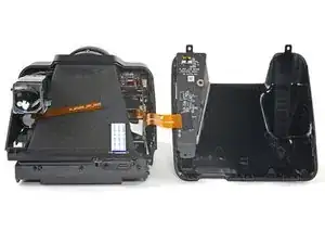
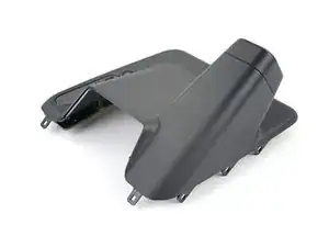
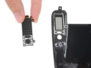
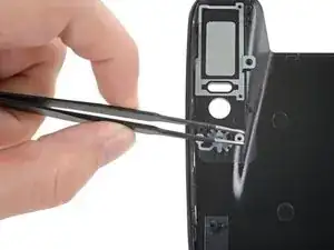
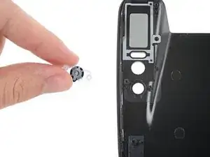
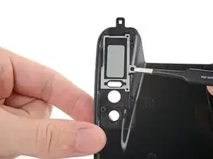
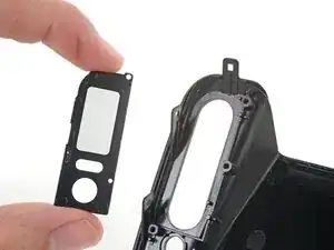
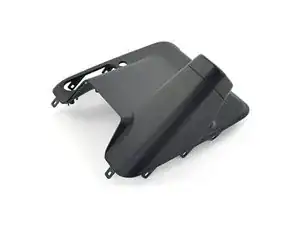
Use this guide to replace a cracked or damaged back cover (the back section of the shell that covers the viewfinder) in your Polaroid I-2 camera.

The clips securing the plastic covers are strong and require significant prying. Don't use metal tools to avoid marring the plastic.

  1. jNIhBLYAKUEFRSwD
    jNIhBLYAKUEFRSwD
    hiU1snQqEYDaCHUP
    cJCgTagQWCE2Wpnh
    • If you have any film left, take some photos and remove the cartridge! Disassembly will expose the film and damage it.

    • Before you begin:

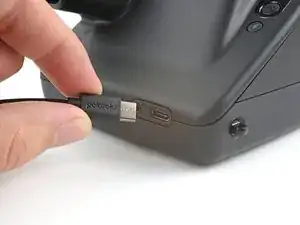
    • Power down and unplug your camera.

    • Put on the lens cap to avoid scratching your lens during disassembly.

  2. lE5jChZKKoyRbTuu
    lE5jChZKKoyRbTuu
    XEQl4IiUMLNJxpx5
    • In the following steps, "left" and "right" are written from the perspective of using the camera—or when the lens is facing away from you.

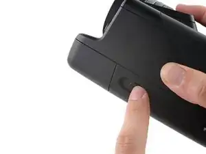
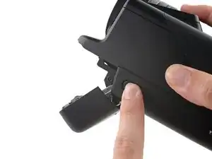
    • Use the latch on the left side of the camera to open the film door.

  3. XJSsoywxEUQDnh1Y
    XJSsoywxEUQDnh1Y
    abBjlAsjRMJ1lN4y
    axYCAxjmaGhGArjh
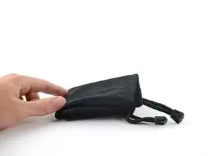
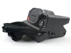
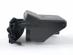
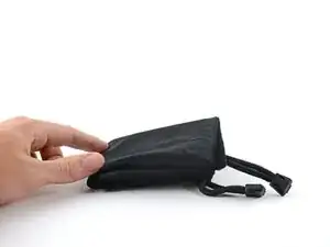
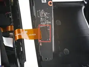
    • Fold a piece of cloth or napkin (or the included bag) into a small square.

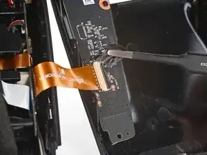
    • Insert the cloth into the film compartment far enough to block the film door from closing during disassembly.

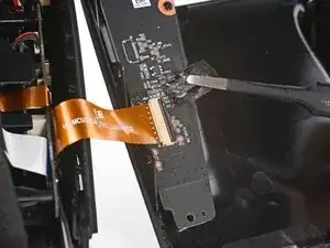
  4. DNxvJhpInTBBAxlK
    DNxvJhpInTBBAxlK
    BZZY3jqQGNhMXRHw
    IMY4fWiDNrgCl4jg
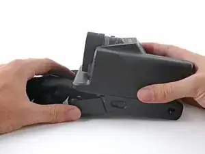
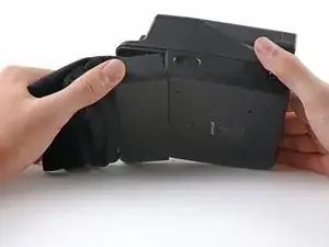
    • Flip the camera over, making sure the cloth stays lodged in the film compartment.

  5. YFDmHemcEMHSbxoJ
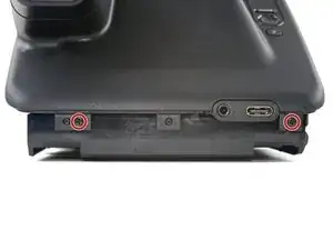
    • Use a Phillips screwdriver to remove the four 3.9 mm-long screws securing the bottom cover.

  6. Y1yLiJdn45vlBDwY
    Y1yLiJdn45vlBDwY
    RISilDSL2lNBawpM
    KRIL5ZtfNNTubZy3
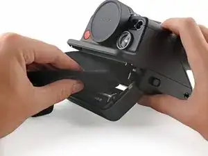
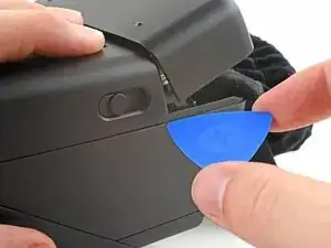
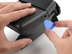
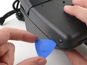
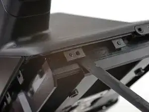
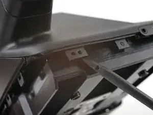
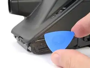
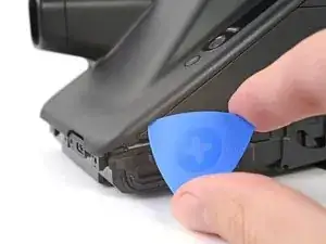
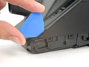
    • Insert the tip of an opening pick under the top left corner of the bottom cover, near the slider button.

    • Tilt the pick up and push to position the pick between the bottom and front covers.

  7. aoDAHGfLBuJeKjQa
    aoDAHGfLBuJeKjQa
    o2Kxt4OGfXrBTRcf
    PXgBLiJ6gflDtque
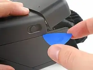
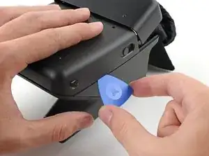
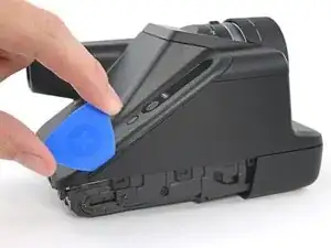
    • Slide the opening pick toward the rear of the camera to release the clips along the left edge.

    • Leave the opening pick at the bottom left corner to prevent the clips from resecuring.

  8. UBcDiHe3HWoqWFTn
    UBcDiHe3HWoqWFTn
    VeYqsFT5OQ1AQyBD
    QFOQEAuNIQOyTUlx
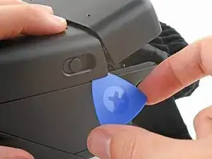
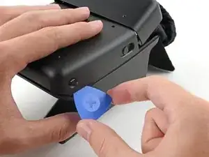
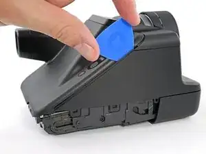
    • Insert the tip of a second opening pick under the top right corner of the bottom cover.

    • Tilt the pick up and push to position the pick between the bottom and front covers.

  9. qNMWfmfuiXgyPol6
    qNMWfmfuiXgyPol6
    lRtGYOY2H2GoKN2v
    KaXR4AEEsyjysvsI
    • Slide the opening pick toward the rear of the camera to release the clips along the right edge.

  10. bYAOJ56UdAASmvOR
    bYAOJ56UdAASmvOR
    GpLM3VOaLJTjaPtw
    jTeE41iGFbyDoRkN
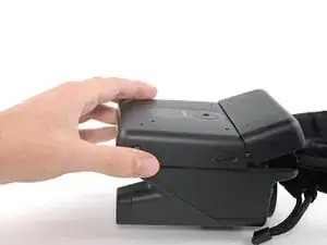
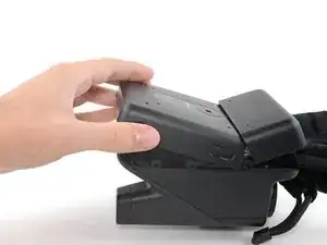
    • At this point, the bottom cover clips should be released. If not, slide an opening pick along the perimeter of the back cover to release any remaining clips.

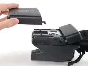
    • Tilt the back of the bottom cover upward and pull it away from the camera, making sure to thread the film door lever from its recess.

    • Remove the back cover.

    • During reassembly, insert the film door lever into its recess before aligning the bottom cover and pressing it into place to secure its clips.

  11. 2t4Cp2WDEGygBhG2
    • At this point, you can remove the blocker from the film compartment.

  12. tHDfEaBQlEZ2UMtT
    • Use a Phillips screwdriver to remove the two 3.9 mm-long screws securing the back cover.

  13. MWpXSFTDHtvp1wYC
    MWpXSFTDHtvp1wYC
    L1KJSD25WEnTQFZx
    mbIvV3SNWSQUpP2Y
    • There are two alignment pegs along the bottom edge of the back cover.

    • Insert a spudger between the frame and the alignment hole on the back cover.

    • Twist the spudger to lift the back cover off of the alignment peg.

    • Repeat for the second alignment peg.

  14. XN1VAO6FPOmhBwWK
    XN1VAO6FPOmhBwWK
    iLWBd4HxNQOatUFZ
    TKOpYKKYYN6POkIM
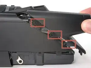
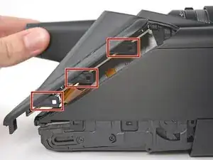
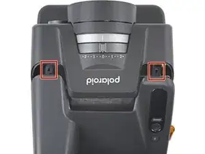
    • There are eight large clips that secure the back cover. The next four steps show how to release them.

    • These clips are very strong and require significant force to release.

    • The procedure to release the clips is tricky and will require time and patience to perform correctly.

  15. oUIiHhU16LDiblrX
    oUIiHhU16LDiblrX
    tdvKXDpRjOxLU2rU
    RO2Un3oavIWJ1wFr
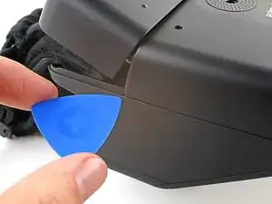
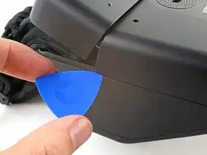
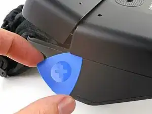
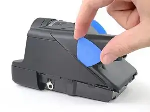
    • Releasing the clips requires getting a tool between the covered "thin" edge of the front cover and the clips themselves.

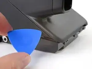
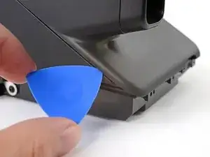
    • Angle an opening pick upward and insert it at the gap where the bottom right corner of the back cover meets the triangular tip of the front cover’s right edge.

    • Push the pick up to get it above the overhanging lip in the back cover.

    • You'll see the plastic warp a little. This is normal.

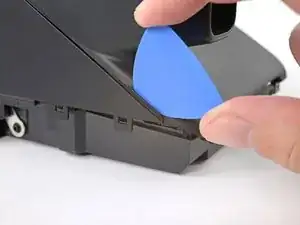
    • While pushing upward, slowly rotate the pick towards the left edge of the camera until it's under the front cover.

    • The pick can slip out easily, so this may take a few tries.

  16. t4QX42HBnZWBVolP
    t4QX42HBnZWBVolP
    n2k2WDNexX2tYU2J
    45ChBVbVaUFJIZNc
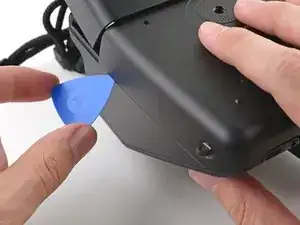
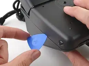
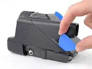
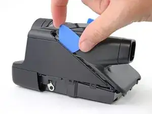
    • While pushing the pick downward, slide it all the way up the right edge to release the clips.

    • Keep the pick as upright as possible while sliding to avoid hitting the clips.

    • The plastic in the lip of the back cover will warp. This is normal.

    • Leave the pick at the top corner before continuing to prevent the clips from resecuring.

  17. ZSYMW5YfJE1YivDn
    ZSYMW5YfJE1YivDn
    ErSdNa6QJlvhqHW4
    m4HwsiWvoqKomZje
    • Angle a second opening pick upward and insert it at the gap where the bottom left corner of the back cover meets the triangular tip of the front cover’s left edge.

    • Push the pick up to get it above the overhanging lip in the back cover.

    • You'll see the plastic warp a little. This is normal.

    • While pushing upward, slowly rotate the pick towards the right edge of the camera until it's under the front cover.

    • The pick can slip out easily, so this may take a few tries.

  18. ovEABUGf4fLARYxV
    ovEABUGf4fLARYxV
    VRP2JCH4DkAWmWDe
    yapEAUKlENvLTGWU
    • While pushing the pick downward, slide it all the way up the left edge to release the remaining clips.

    • Keep the pick as upright as possible while sliding to avoid hitting the clips.

    • The plastic in the lip of the back cover will warp. This is normal.

  19. B4iY2Bj143ryNrTt
    B4iY2Bj143ryNrTt
    jTyKEO1MGFWbtUhx
    LiQ4Bb1EvrETdcEJ
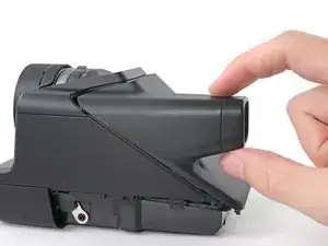
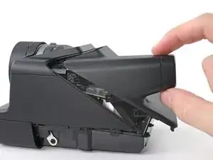
    • Don't try to pull the back cover off just yet, as it's still connected by a cable.

    • At this point, the back cover should feel loose. If any parts still feel connected, repeat the last four steps until all the clips release.

    • Pull the back cover off the camera and rotate it over the right edge to expose the flex cable.

    • During reassembly, make sure the the flex cable isn't caught between the covers before re-engaging the clips.

  20. lpOnaDBUU6inXWCK
    lpOnaDBUU6inXWCK
    n1ooA3IBvRKsFieU
    4HEEfooMiVn3pKAP
    • Use tweezers to peel off the tape covering the interconnect cable ZIF connector on the control board.

    • Set the tape aside. You'll reuse it during reassembly.

  21. VS2FrbSMIIFIPoEy
    VS2FrbSMIIFIPoEy
    mVnkGYDhPBVEHPJm
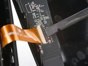
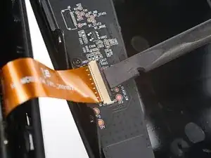
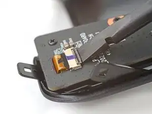
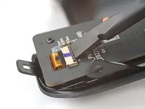
    • Use the flat end of a spudger to lift up the locking flap on the control board ZIF connector.

  22. i3oQNCwhUa5CCk6p
    i3oQNCwhUa5CCk6p
    VpeUd1x6vYkVEaj1
    Md4jYoyVyDvw1Vi6
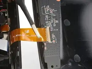
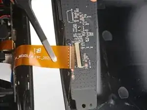
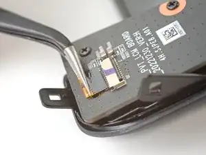
    • Use tweezers to pull the interconnect cable out of its slot in the control board.

    • Remove the back cover.

  23. eiyNLpnPHXrRVC1u
    eiyNLpnPHXrRVC1u
    eLei6SlxPmKGbhBV
    • Use the flat end of a spudger to lift up the locking flap on the display cable ZIF connector at the top of the control board.

  24. 6nJamwdGf5JmM1tN
    6nJamwdGf5JmM1tN
    5OYHHlGC6wQEERHU
    • Use tweezers to pull the display cable out of its slot in the control board.

  25. peAtv5X1P33DAnHW
    • Use a Phillips screwdriver to remove the three 5.9 mm-long screws securing the control board.

  26. fCjmLaT1jy42bNQS
    fCjmLaT1jy42bNQS
    ny22D4UWovuvtARo
    • Lift the control board off its alignment pegs and remove it, making sure to thread the display cable through its slot.

    • During reassembly, make sure the control board is slotted into its pegs and the display cable is threaded through its slot before securing it to the back cover.

  27. 3EaEYXJJMaMgyyOf
    3EaEYXJJMaMgyyOf
    ZTfQuluU6DaOFABY
    • Lift the display assembly out of its recess in the back cover and remove it.

  28. S12NNeDTNXVQvJZT
    S12NNeDTNXVQvJZT
    PXRRRPyMIbW3fI6i
    • Pull the flash button off of its two alignment pegs and remove it.

    • During reassembly, check the front of the button to make sure it's oriented correctly before putting it back on its pegs. It will only fit one way.

  29. QcWiRSDKH66LwE5R
    QcWiRSDKH66LwE5R
    UAD52B4hm6wMHhfe
    5DILAMGEcd4Tfcd3
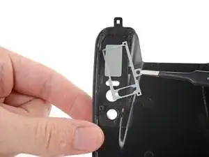
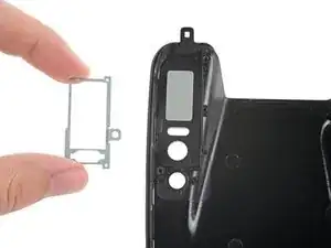
    • Use tweezers to grab the screw hole tab along the right edge of the metal display frame.

    • Pull away from the back cover to separate the display frame from its two alignment pegs.

  30. yC2XFLX1bMwgdtHG
    yC2XFLX1bMwgdtHG
    LnC3cX1gu6KmMDJm
    iPNAXKTRG5X4AX4t
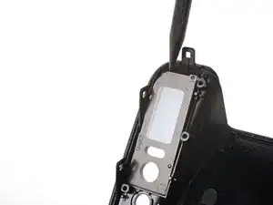
    • Insert the tip of a spudger between the top left corner of the display cover and the back cover.

    • Pry up to separate the display cover from its two alignment pegs.

    • Remove the display cover.

  31. ECQl1nyx3CAAPIae
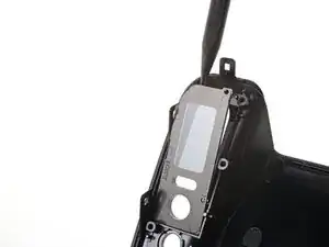
    • You're now left with the back cover by itself.

Conclusion

Compare your new replacement part to the original part—you may need to transfer remaining components or remove adhesive backings from the new part before you install it.

To reassemble your device, follow these instructions in reverse order.

Take your e-waste to an R2 or e-Stewards certified recycler.

Repair didn’t go as planned? Try some basic troubleshooting, or ask our Polaroid I-2 Answers community for help.
Alex Diaz-Kokaisl

Member since: 16/01/22

117881 Reputation

0 comments