Introduction
Tools
-
-
Remove three 5.3 mm #00 screws (the bottom-most screw is not always present).
-
Remove one 7.3 mm #00 screw.
-
Remove the remote trigger cover.
-
-
-
Remove two 5.3 mm #00 screws by the eyepiece.
-
Remove one 6.8 mm #00 screw in the battery compartment.
-
Remove one 7.0 mm #00 screw near the take up spool.
-
-
-
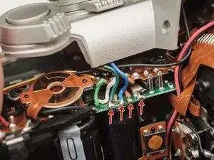
De-solder the green, blue, brown and black wires from the flash PCB.
-
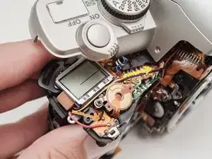
De-solder the black wire.
-
Pull out slack in the black wire so you can comfortably work on the underside of the top cover.
-
-
-
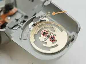
Remove two #00 screws
-
Be careful not to damage the feeler contacts from the drive mode switch throughout the repair. There are delicate and easily bent.
-
-
-
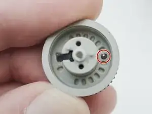
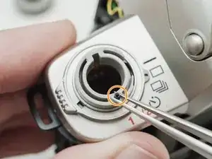
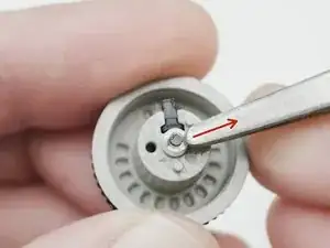
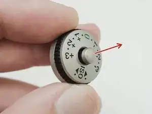
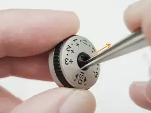
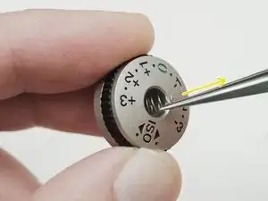
Remove the ball bearing from the inside of the dial.
-
Remove the detent spring from the top cover.
-
-
-
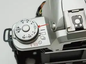
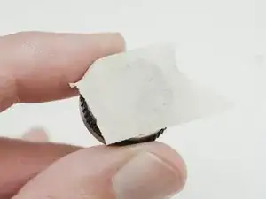
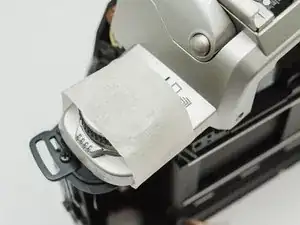
Use tape to hold components in place when reassembling the lock button and installing the dial.
-
To reassemble your device, follow these instructions in reverse order.


