Introduction
If your Panasonic Lumix DMC-ZS35 camera’s won’t turn on, or if there’s another component of the camera that isn’t functioning as intended, it may be an issue with the Lumix motherboard. By following this guide, you’ll be able to remove and replace the motherboard to your Lumix.
Before you replace the motherboard, take a look at this Troubleshooting Guide to see if there is a simpler solution to your problem. Before beginning, make sure to turn off your camera completely and remove its battery.
-
-
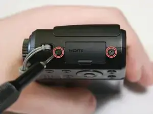
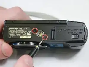
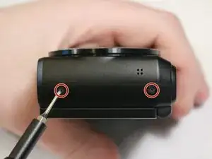
Remove the six 4mm screws located on the side and bottom of the camera casing using a Phillips #000 screwdriver.
-
-
-
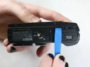
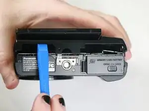
Use a plastic opening tool to carefully separate the back casing from the main body of the camera. It's advised to run along the entire "seam" of the casing and the camera with the tool to ensure full separation.
-
-
-
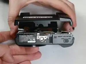
Gently pry apart the back casing from the body of the camera. It's recommended to apply as minimal force as is necessary to prevent unintended damage to the camera or the casing.
-
-
-
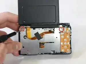
Unscrew the four 3mm screws holding the LCD screen hinge in place using a Phillips #000 screwdriver.
-
-
-
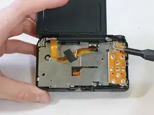
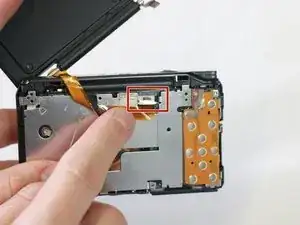
Gently pull LCD screen ribbon cable from internal port to disconnect the screen and prevent unwanted damage.
-
Lift the freed LCD screen from the base camera to complete the process.
-
-
-
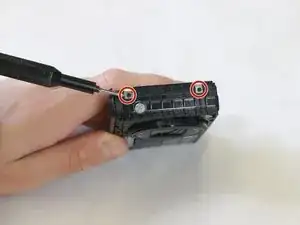
Remove the four 2mm Phillips #000 screws on the sides of the exposed internal metal plate within the camera.
-
-
-
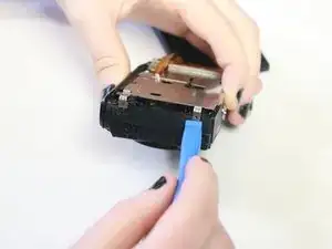
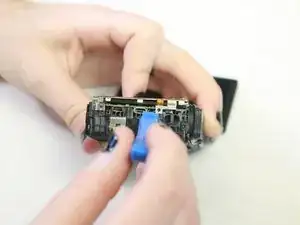
Using an iFixit opening tool, gently remove the plating.
-
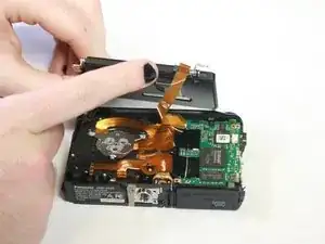
Carefully remove the ribbon cable connecting the plating with the lens component.
-
-
-
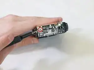
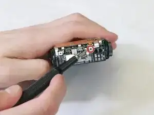
Remove the 2mm screws holding the lens in place with a Phillips #000 screwdriver, located along the perimeter of the lens component within its housing.
-
-
-
Carefully lift the lens component from the housing once it is freed.
-
Ensure that all connectors and cables are disconnected between the lens and other components before separation.
-
-
-
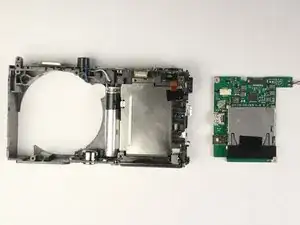
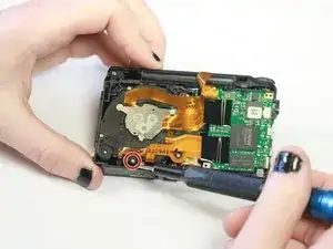
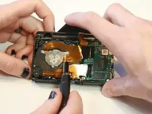
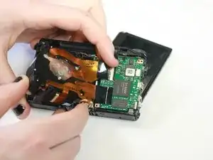
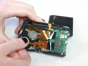
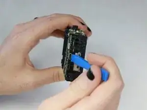
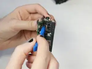
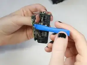
Using the opening tool, gently pry off the mother board. Run the opening tool along the outer edges of the motherboard as necessary to loosen it until it is fully removed.
-
To reassemble your device, follow these instructions in reverse order.