
Introduction
Use this guide to replace the screen on your OnePlus Nord 2 5G.
You'll need replacement adhesive in order to complete this repair.
-
-
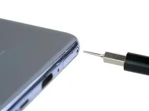
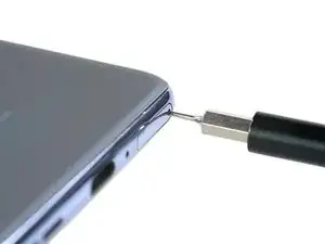
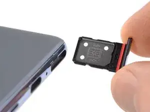
Insert a SIM card eject tool into the small hole in the SIM card tray, located on the upper left edge edge of the phone.
-
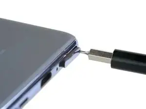
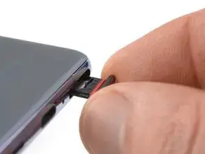
Press firmly to eject the tray.
-
-
-
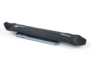
Prepare an iOpener and apply it to the rear glass for at least three minutes to loosen the adhesive underneath.
-
-
-
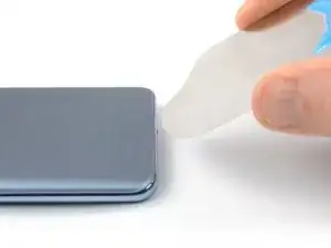
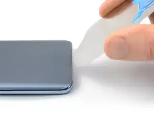
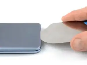
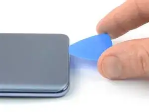
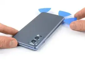
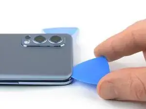
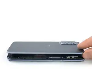
Insert an iFlex into the seam between the rear glass and the midframe at the bottom edge of the phone to create a gap. This may require some force.
-
Leave the iFlex in place to prevent the adhesive from resealing.
-
-
-
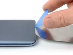
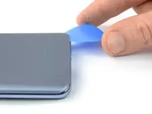
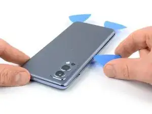
Slide the opening pick to the bottom right corner to slice the adhesive.
-
Leave the opening pick in place to prevent the adhesive from resealing.
-
-
-
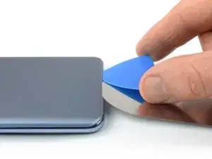
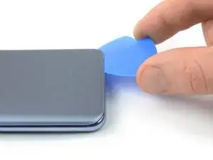
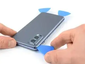
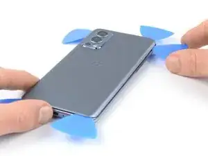
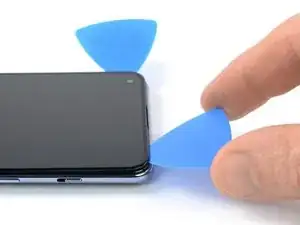
Insert a second opening pick at the bottom right corner of your phone.
-
Slide the opening pick to the bottom left corner to slice the adhesive.
-
Leave the opening picks in place to prevent the adhesive from resealing.
-
-
-
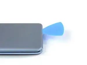
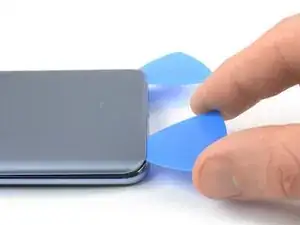
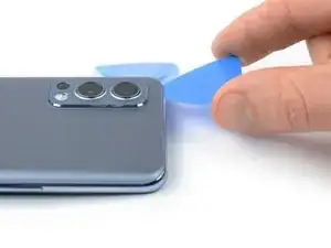
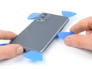
Insert a third opening pick at the bottom left corner of your phone.
-
Slide the opening pick along the left edge of your phone to slice the adhesive.
-
Leave the opening pick in the top left corner to prevent the adhesive from resealing.
-
-
-
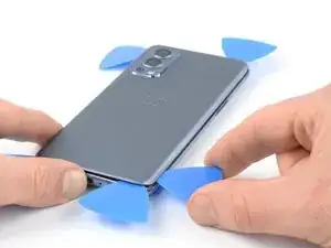
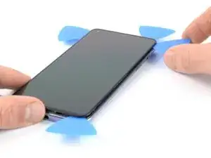
Insert a fourth opening pick underneath the top left corner of the rear glass.
-
Slide the opening pick along the top edge to slice the adhesive.
-
Leave the opening pick in the top right corner to prevent the adhesive from resealing.
-
-
-
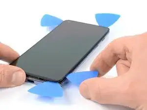
Insert a fifth opening pick underneath the top right corner.
-
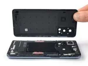
Slide the opening pick along the right edge of the back cover to slice the remaining adhesive.
-
-
-
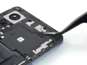
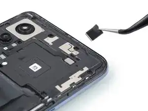
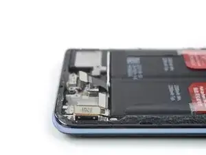
Use the point of a spudger to disconnect the flash assembly cable by prying the connector straight up from its socket.
-
-
-
Use a Phillips screwdriver to remove the nine 3.8 mm-long screws securing the motherboard cover.
-
-
-
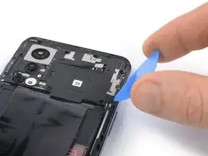
Insert an opening pick underneath the bottom right edge of the motherboard cover.
-
Twist the opening pick sideways release the plastic clips and to pry up the motherboard cover.
-
-
-
Use a spudger to disconnect the battery cable by prying the connector straight up from its socket.
-
-
-
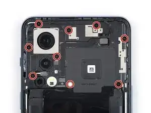
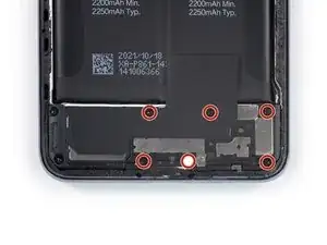
Use a Phillips screwdriver to remove the six 3.8 mm-long screws securing the daugtherboard cover.
-
-
-
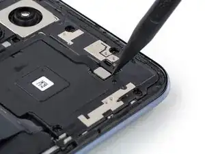
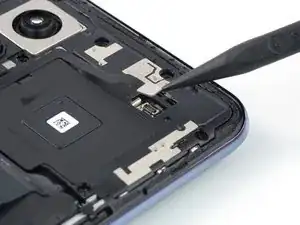
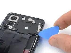
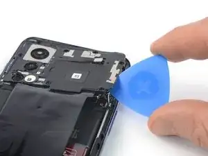
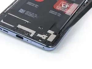
Insert the point of a spudger underneath the top right edge of the daughterboard cover.
-
Pry upwards to loosen the daughterboard cover.
-
-
-
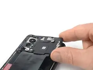
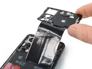
Fold the daughterboard cover to the left like you would open the front cover of a book.
-
Carefully peel the black tape off of the loudspeaker.
-
Remove the daughterboard cover.
-
-
-
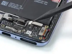
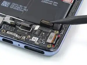
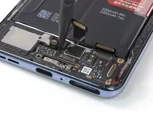
Use a spudger to disconnect the interconnect and the antenna board cables by prying the connectors straight up from their socket.
-
-
-
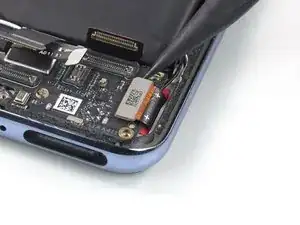
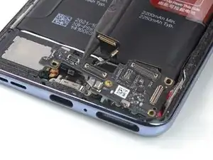
Use a spudger to disconnect the fingerprint sensor and the interconnect cables by prying the connectors straight up from their sockets.
-
-
-
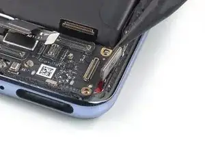
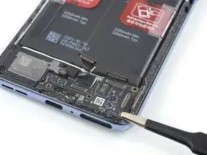
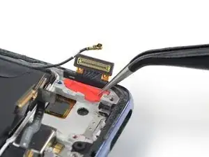
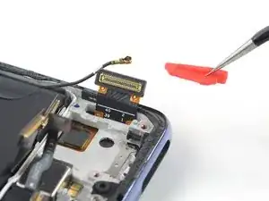
Use a spudger to disconnect the display cable by prying the connector straight up from its socket.
-
-
-
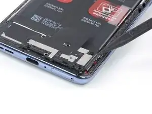
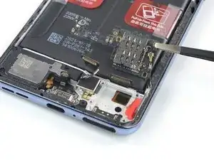
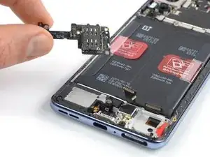
Insert the point of a spudger underneath the top edge of the daughterboard.
-
Pry upwards to loosen the daughterboard.
-
-
-
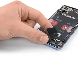
Use a pair of blunt nose tweezers to carefully fold the daughterboard over in direction of the battery.
-
-
-
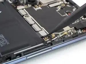
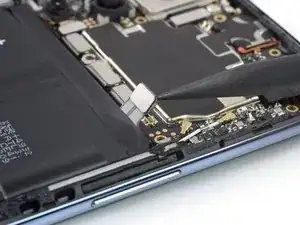
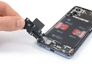
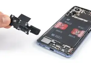
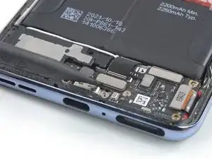
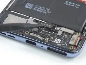
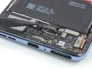
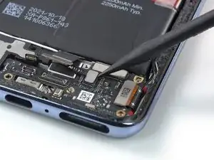
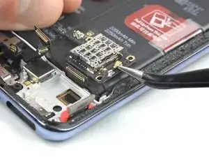
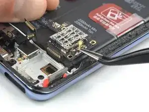
Slide a one arm of a pair of tweezers under the black antenna cable until they're snug against the metal connector.
-
Disconnect the upper antenna cable by prying it straight up from the daughterboard.
-
-
-
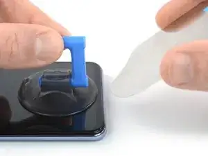
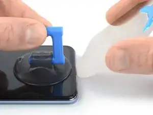
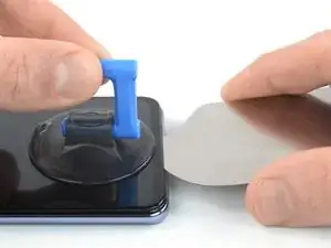
Apply a suction handle to the bottom edge of the screen.
-
Lift the screen with the suction handle and insert an iFlex to create a small gap between the screen and the phone assembly.
-
-
-
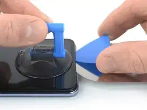
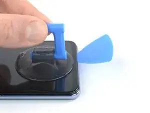
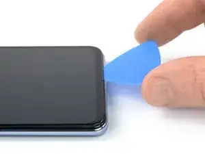
Slide the opening pick to the bottom right corner of the screen to slice its adhesive.
-
Leave the opening pick in place to prevent the adhesive from resealing.
-
-
-
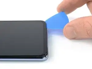
Insert a second opening pick at the bottom right corner and slide it to the bottom left corner of the screen to slice the adhesive.
-
Leave the opening pick in place to prevent the adhesive from resealing.
-
-
-
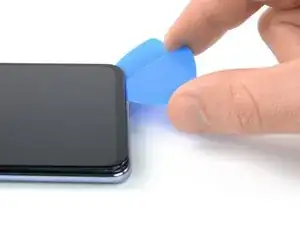
Insert a third opening pick underneath the bottom left corner of the screen.
-
Slide the opening pick along the left edge of the screen to slice the adhesive.
-
Leave the opening pick in the top left corner to prevent the adhesive from resealing.
-
-
-
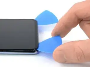
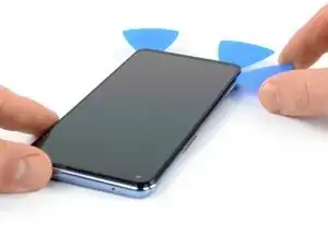
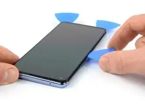
Insert a fourth opening pick at the top left corner of the screen.
-
Slide the opening pick along the top edge of the phone to slice the adhesive.
-
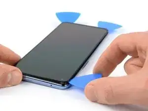
Leave the opening pick in the top right corner to prevent the adhesive from resealing.
-
-
-
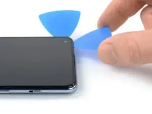
Insert a fifth opening pick and slide it along the right edge of the phone to slice the remaining adhesive.
-
-
-
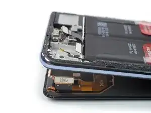
Carefully thread the display cable through the gap in the midframe by lifting the bottom of the phone.
-

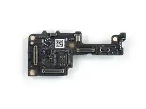
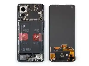
Compare your new replacement part to the original part—you may need to transfer remaining components or remove adhesive backings from the new part before you install it.
To reassemble your device, follow these instructions in reverse order.
During reassembly, apply new adhesive where it's necessary after cleaning the relevant areas with isopropyl alcohol (>90%).
Take your e-waste to an R2 or e-Stewards certified recycler.
Repair didn’t go as planned? Try some basic troubleshooting, or ask our OnePlus Nord 2 5G answers community for help.

One comment
The procedure to mount it back is the same as dismounting it, but for a begginer like me some advice on how to put glue or tape would be usefull.