Introduction

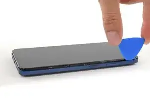
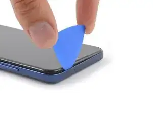
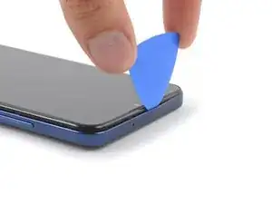
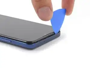
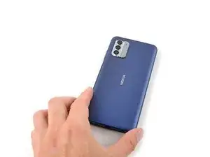
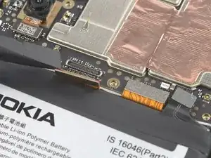
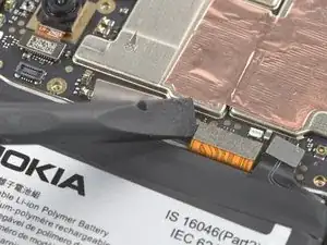
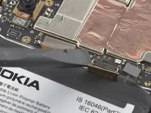
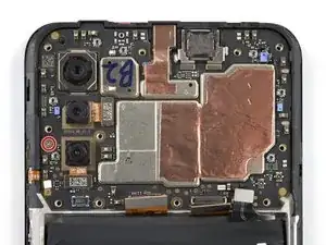
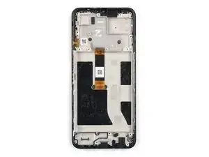
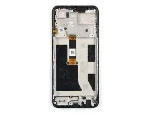
Use this guide to replace a broken screen on your Nokia G310 5G.

This guide is written for the genuine Nokia G310 5G screen assembly. The assembly consists of the screen and midframe together as one part. Make sure you have the correct part before you begin this repair.

Note: This procedure requires transferring your phone's internals into the new assembly.

For your safety, turn on your phone and allow the battery to discharge below 25% before starting this procedure. This reduces the risk of fire if the battery is accidentally damaged during the repair. If your battery looks puffy or swollen, take extra precautions.

  1. 2gdDZwvEnoSLNEfX
    2gdDZwvEnoSLNEfX
    rc6kEZEhNbFhpGIg
    hS54eEdGWfOfxfvx
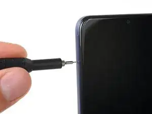
    • Power down your phone and unplug any cables.

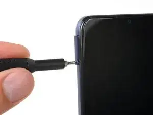
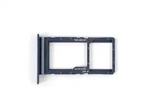
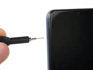
    • Insert a SIM eject tool, bit, or a straightened paper clip into the small hole on the SIM card tray on the upper left edge of the phone.

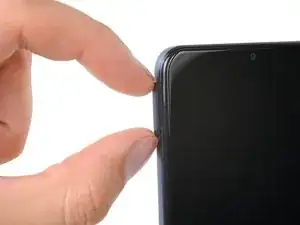
    • Press firmly to eject the tray.

  2. uS1a3KKLK3S1SGmv
    uS1a3KKLK3S1SGmv
    fJbOEOtvDS2V1ls5
    d5smrTZNHCQCZlQp
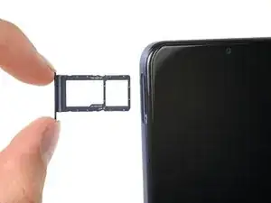
    • Remove the SIM card tray.

    • When installing either a SIM card or a microSD card, make sure they're in the correct orientation and sitting completely flush with the edges of the tray before reinserting the tray into the phone.

  3. 1mD6AEajawgWeXmE
    1mD6AEajawgWeXmE
    phJm5HU6WbWPIFCc
    XM5aElYRbgaxGunQ
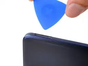
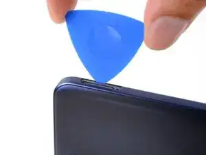
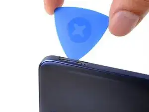
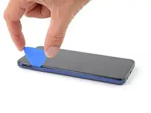
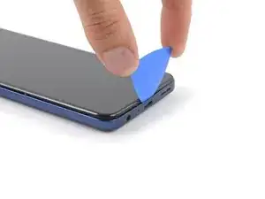
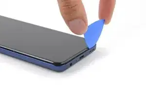
    • The back cover is held in place by plastic clips.

    • Insert an opening pick under the small notch in the SIM card tray slot.

  4. C5fPPEWcYcWSJrYl
    C5fPPEWcYcWSJrYl
    fTuFTTWhtkbPsB5I
    AQIxGoMNE6PR3m2G
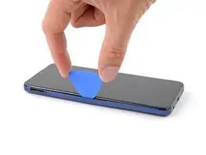
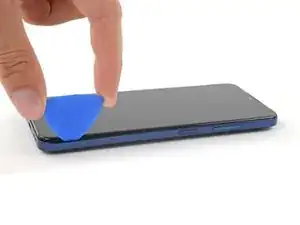
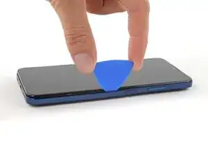
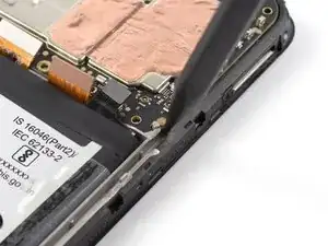
    • Position the opening pick at a steep downward angle between the back cover and the screen assembly.

    • Slide the opening pick down the left edge of the phone to release the plastic clips.

  5. xYjuYYKBYhifBx2f
    xYjuYYKBYhifBx2f
    iRFPMdly2FRMGLDG
    TF2vP6yQmPugSBPn
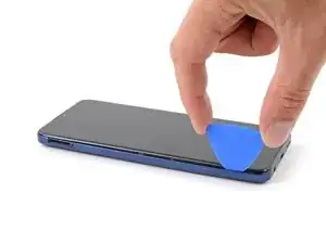
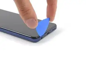
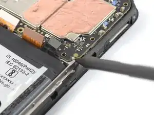
    • Turn the opening pick around the corner and continue to slide it along the bottom edge to release the plastic clips.

  6. edYNbCHTXErtucUV
    edYNbCHTXErtucUV
    vWKSuMGAxBkDsI4I
    TL2VM46x2EU4siBe
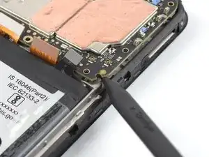
    • Slide the opening pick up the right edge to continue releasing the plastic clips.

  7. wYcYXwraYE33uMfN
    wYcYXwraYE33uMfN
    NTbXENiHqKCpjcXk
    orZWFNSZNYo1XJAl
    • Slide the opening pick along the top edge to release the remaining plastic clips.

    • Don't try to fully remove the back cover just yet, as it's still connected with a cable.

  8. YuDWI1yfMY5upJ4C
    YuDWI1yfMY5upJ4C
    DtmsNKJVVmGGZZ2F
    v1uCUiOiwbbFGTSZ
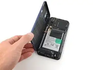
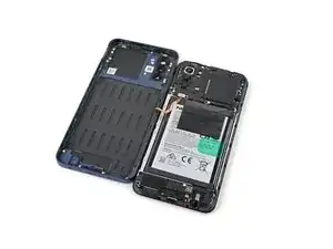
    • With the phone laying screen-side down, carefully lift the right edge of the back cover, opening it like a book.

    • Take care not to strain or tear the attached fingerprint reader cable during this procedure.

    • Lay the back cover next to the phone.

  9. E6pxGORaJFKFnKhi
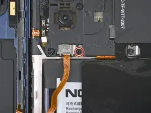
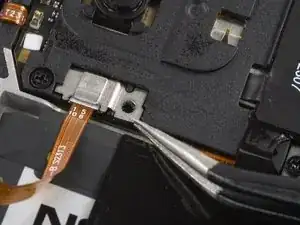
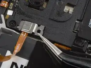
    • Use a Phillips screwdriver to remove the 3.8 mm‑long screw securing the fingerprint reader bracket.

  10. XnpfXQAqqVOjhkTn
    XnpfXQAqqVOjhkTn
    OP3IHr2ygLRRT1yA
    afSWqrK1dIwhgrab
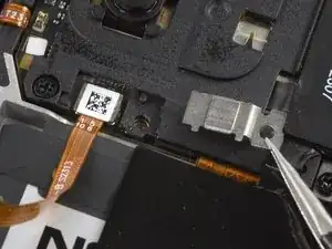
    • Use a pair of tweezers or your fingers to remove the fingerprint reader bracket.

    • Take care not to puncture the battery with sharp tools—a punctured or creased battery may leak dangerous chemicals or cause a fire.

    • During reassembly, make sure to slide the bracket's edge back into its slot under the motherboard cover.

  11. wxsbUP6pYVg2X5Vq
    wxsbUP6pYVg2X5Vq
    WrYCCYnfXPeiEZRX
    IOXSYqTm6mSkPC2n
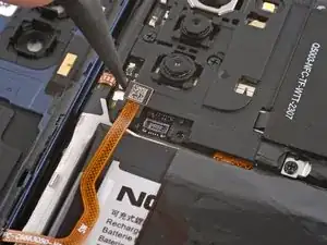
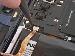
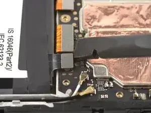
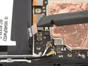
    • Use the pointed end of a spudger to disconnect the fingerprint reader by prying the connector straight up from its socket.

    • To re-attach press connectors like this one, carefully align and press down on one side until it clicks into place, then repeat on the other side. Don't press down on the middle. If the connector is misaligned, the pins can bend and cause permanent damage.

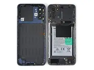
    • Remove the back cover.

  12. N1qWPTJ1UnQUZKvR
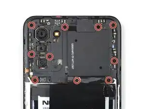
    • A white sticker might cover one of the top screws. Pierce through it with the tip of your screwdriver or use a pair of tweezers to remove it.

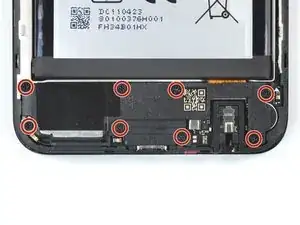
    • Use a Phillips screwdriver to remove the ten 3.8 mm-long screws securing the motherboard cover.

  13. w5IqZQGYTGZo3PUs
    w5IqZQGYTGZo3PUs
    xSOdSpYAEbjbr4ir
    jUUuEG4nSlYdnjb3
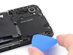
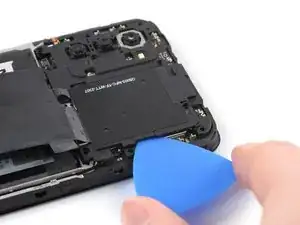
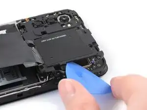
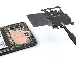
    • The motherboard cover is further held in place by plastic clips.

    • Insert an opening pick under the right edge of the motherboard cover.

    • Twist the opening pick to release the plastic clips.

  14. oCPGCYlL2vTt4JSI
    oCPGCYlL2vTt4JSI
    3IBiq3Z3ijgY1B1O
    vKZSWFmArHREskSu
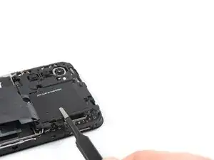
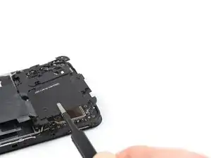
    • Use a pair of tweezers or your fingers to remove the motherboard cover.

  15. FWt4E4QTDY3MotYi
    FWt4E4QTDY3MotYi
    AoghcSaAHaDCK33o
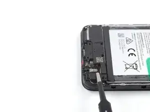
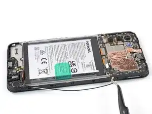
    • Use the flat end of a spudger to disconnect the battery cable by prying the connector straight up from its socket.

  16. 1cVe41XQLnBt2KSQ
  17. 6KSq316WiUu1SYGn
    6KSq316WiUu1SYGn
    Kveh6ZQOlqtUdVKP
    4EhVkKOaUAp4nCfI
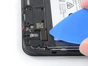
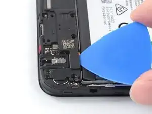
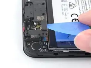
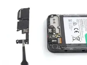
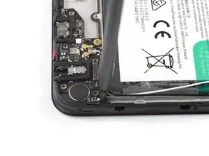
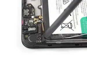
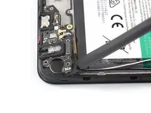
    • Insert an opening pick underneath the top right edge of the loudspeaker.

    • Avoid pushing down at a sharp angle, or you risk damaging the interconnect ribbon cable underneath.

    • Twist the opening pick to release loudspeaker from the plastic clips holding it in place.

  18. VGwPxZIXqgSaHlA5
    VGwPxZIXqgSaHlA5
    MBPR4rfLs6CXPNgm
    • Use a pair of tweezers or your fingers to remove the loudspeaker.

  19. pjjrJn6aBXS6XtUs
    pjjrJn6aBXS6XtUs
    FgXSSEKRGoygCMET
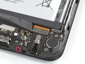
    • Use the flat end of a spudger to disconnect the interconnect cable by prying the connector straight up from its socket.

    • To re-attach press connectors like this one, carefully align and press down on one side until it clicks into place, then repeat on the other side. Don't press down on the middle. If the connector is misaligned, the pins can bend and cause permanent damage.

    Hello there, I have damaged the interconnect cable during the screen replacement process, do you offer replacement cables for sale?

    oliver gray -

    Hello Oliver, unfortunately we currently do not have interconnect replacement cables available in the iFixit store. In this case, please reach out to Nokia Phones support!

    Manuel Haeussermann -

  20. GWsOEUHZMhSOIUtO
    GWsOEUHZMhSOIUtO
    1pYOLjHveLquCXTg
    UISpQHiFAfVmEc34
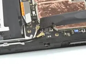
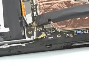
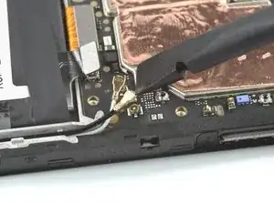
    • Use a spudger to disconnect both antenna cables by prying their connectors straight up from the sockets on the motherboard.

  21. YSrMmXdJTvBdL2mg
    YSrMmXdJTvBdL2mg
    cTLMI6ciOYVoVJxc
    XstCMOGf1htfXxTq
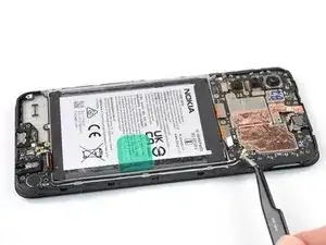
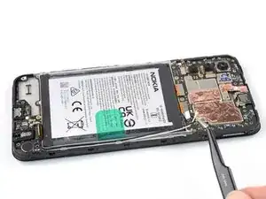
    • Use a pair of tweezers or your fingers to lift the antenna cables out of their recess in the frame.

    • During reassembly, connect the white antenna cable to the motherboard before connecting the black antenna cable. Then reseat the antenna cables into their recess.

  22. WroemjUOPFxgrb4n
    WroemjUOPFxgrb4n
    6PFD1lxsWtKJR5kE
    S2ftAU1hXCUppbY1
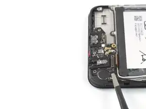
    • The charging port assembly is held in place with mild adhesive.

    • Insert the flat end of a spudger underneath the top right edge of the charging port assembly.

    • Pivot the charging port assembly up until you can grip it with your fingers.

  23. QfXgp1coGxfFJquF
    QfXgp1coGxfFJquF
    Glnxvs5x6kwxNQNt
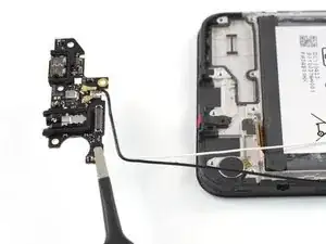
    • Use a pair of tweezers or your fingers to remove the charging port assembly.

  24. G4BVcCePWhyhXecD
    G4BVcCePWhyhXecD
    2ILD6FpdHFH6sXRW
    OddJMPtbLRhmAUjG
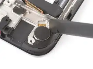
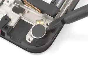
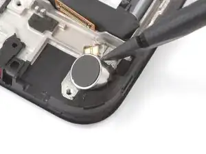
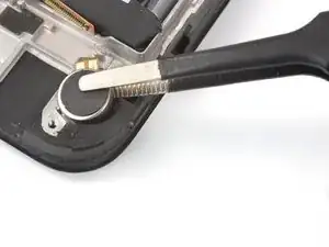
    • The vibration motor is held in place with mild adhesive.

    • Insert the flat end of a spudger into the small recess on the upper right side of the vibration motor.

    • Pivot the spudger up to pry up the vibration motor off of the adhesive securing it underneath.

    • During reassembly, you can reuse the old adhesive if it's still sticky. If not, replace it with new custom cut adhesive, such as Tesa Tape.

  25. tbTWSqYYdbTfrsJf
    tbTWSqYYdbTfrsJf
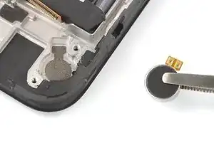
    3PNOOljlTkvtIaN2
    • Use a pair of tweezers or your fingers to remove the vibration motor.

  26. SJJQTvFonmwVsOWL
    SJJQTvFonmwVsOWL
    QRCSSq3UVvFnVKJd
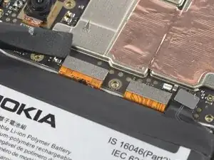
    • Use the flat end of a spudger to disconnect the display cable by prying the connector straight up from its socket.

  27. tniqw6RgLJUURBKm
    tniqw6RgLJUURBKm
    UG1LvgQqeSmqASHj
    • Use the flat end of a spudger to disconnect the interconnect cable by prying the connector straight up from its socket.

    • To re-attach press connectors like this one, carefully align and press down on one side until it clicks into place, then repeat on the other side. Don't press down on the middle. If the connector is misaligned, the pins can bend and cause permanent damage.

  28. lw1ufiRxC6jJVAsJ
    lw1ufiRxC6jJVAsJ
    Za1jlkEcJXWNjnXK
    • Use a Phillips screwdriver to remove the single 2.8 mm‑long screw securing the motherboard.

    2.5 mm-long screw instead of 2.8 mm-long screw.

    Loaurrine -

  29. NTYapyDKWhSph1gk
    NTYapyDKWhSph1gk
    bQRHtk6MNCWNI54d
    sxRQnGVhMQio6cbT
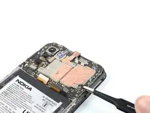
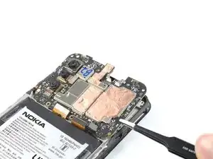
    • Insert the pointed end of a spudger underneath the bottom right corner of the motherboard.

    • Pry the motherboard up until you can grip it with your fingers.

  30. rn6RYggF3UUMCiBG
    rn6RYggF3UUMCiBG
    n3rfKNd1yBec4f1C
    WJy55qj3H6OHctCu
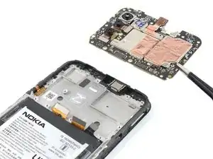
    • Grip the motherboard on the right edge using a pair of tweezers or your fingers.

    • Remove the motherboard.

    • During reassembly, apply small dabs of thermal paste to the marked areas on the new screen assembly. Follow this guide to prepare the motherboard and apply the paste.

  31. YiUsN5ReZ3FaFpGV
    YiUsN5ReZ3FaFpGV
    CXRUCKO4T3xBhBdV
    t2DZBJY6C1T5svJH
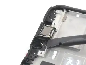
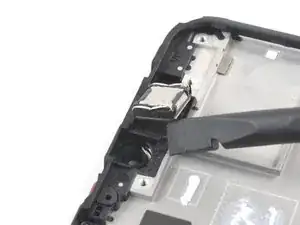
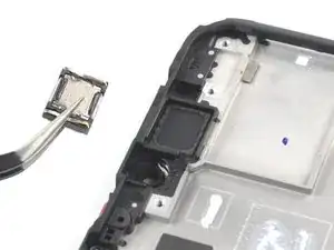
    • The earpiece speaker is secured to the frame with mild adhesive.

    • Insert the flat end of a spudger underneath the bottom left corner of the earpiece speaker and pry it out of its recess.

    • Remove the earpiece speaker.

    • During reassembly, make sure the gold contact springs on the earpiece speaker are facing up and oriented closer to the bottom edge.

  32. pqbS6XR1lIroUTYC
    pqbS6XR1lIroUTYC
    uPkjJqRs4UCMMrQw
    • Be extra careful to not puncture, bend, or deform the battery during the next few steps—a damaged battery may leak dangerous chemicals or cause a fire.

    • Use your fingers to peel the two outer adhesive tabs off of the battery.

  33. 1BToPv6TGHtSDP1D
    1BToPv6TGHtSDP1D
    mkiTZaxHW1xLRWpy
    IHqiLDVSlxfWLTIt
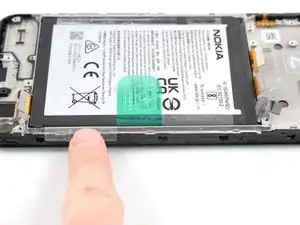
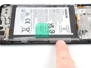
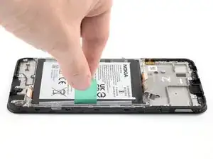
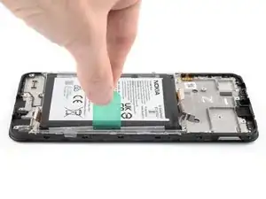
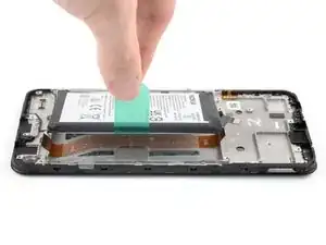
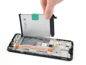
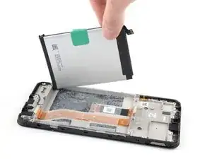
    • The battery is secured to the frame with adhesive. Pull tabs are provided to separate the adhesive and remove the battery.

    • Use your fingers to peel the center green pull tab off of the battery.

    • Using one hand to hold the phone steady, use your other hand to slowly and steadily lift the center green pull tab up to separate the adhesive securing the battery underneath.

    • If the green pull tab rips, use the outer clear tabs instead.

    • If you have any difficulties with stubborn battery adhesive, you can contact Nokia's phones support.

  34. SkIHd5XSyxPAo2Pe
    SkIHd5XSyxPAo2Pe
    g1J34LmkpusyiEFX
    mNGPjceTtGO1csao
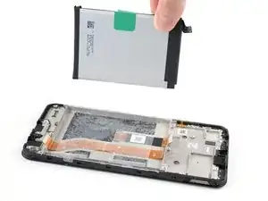
    • Peel the battery off of the adhesive film and remove it.

    • Don't reinstall a damaged or deformed battery, as doing so is a potential safety hazard. Replace it with a new battery.

  35. iWrdXDqjVxMWsxRm
    iWrdXDqjVxMWsxRm
    luYglGaxAQRyRejC
    AZNfSbhiJOKSKLBX
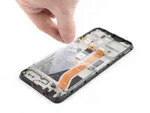
    • Grab the bottom right edge of the leftover adhesive film and pull it towards the top of the phone with steady force to remove it.

    • During reassembly, follow these instructions to apply a new battery adhesive film:

    • Remove the battery adhesive film from its liners and apply it to the battery.

    • Align the bottom edge of the battery (the edge without adhesive) with the bottom edge of the recess.

    • Lower the battery down and press firmly to secure it in place.

  36. WOA2ruIFDNWkkOtR
    WOA2ruIFDNWkkOtR
    kBPpgDGPKOxVnVbQ
    IwhAa13UTyMVCmQF
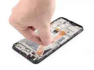
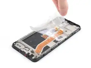
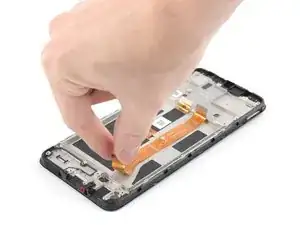
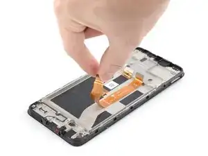
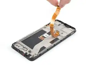
    • The interconnect cable is lightly adhered to the frame.

    • Grab the bottom of the interconnect cable and peel it up towards the top of the phone to remove it.

    • During reassembly, realign the interconnect cable with the etched-in markings on the frame. Before reinstalling the motherboard, make sure the interconnect cable’s top connector is at approximately the same height as the display cable next to it.

  37. WEtDtJ3xPmrqIAnH
    • Only the screen assembly remains.

    • During reassembly, compare your new replacement assembly to the original part:

    • If your part comes with battery adhesive pre-installed, remove its plastic liners before continuing to the previous step.

    • If your part has no battery adhesive, remove the clear liner on the pre-cut battery adhesive and apply the sticky section to the battery well. Remove the opaque liner before continuing to the previous step.

    • If you're reusing your original battery, carefully inspect it for any signs of physical damage. If it's bent, creased, dented, or scratched, replace it with a new battery. Installing a damaged battery is a safety hazard.

    After replacing the screen myself, the phone stopped receiving the network. I had to throw it away and buy a new phone. Waste of money for screen

    Igor Komarov -

    Hello Igor, sorry to hear that you experienced issues following your repair. It sounds like the issue might have been caused by the antenna cable being damaged or disconnected. In these cases, we recommend physically reseating the connectors of the antenna cable on both motherboard and daughterboard as well as checking the cable and connectors for signs of damage. If this doesn't help, you can contact Nokia's phones support to get further support.

    Manuel Haeussermann -

    This worked like a charm! It wasn’t too frustrating and my phone is as good as new!

    Jacqueline Taylor -

Conclusion

To reassemble your device, follow these instructions in reverse order.

Take your e-waste to an R2 or e-Stewards certified recycler.

Repair didn’t go as planned? Try some basic troubleshooting, or ask our Answers community for help.
Clay Eickemeyer

Member since: 19/09/22

65190 Reputation

0 comments