Introduction

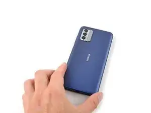
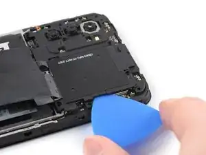
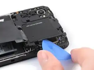
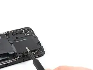
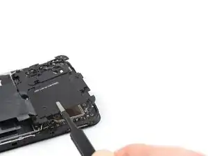
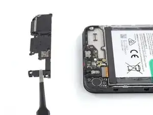
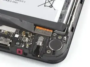
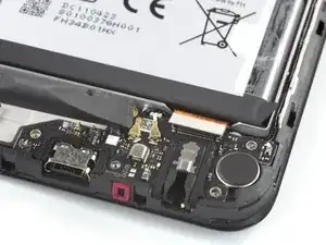
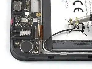
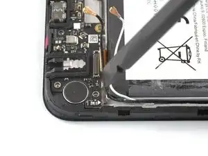
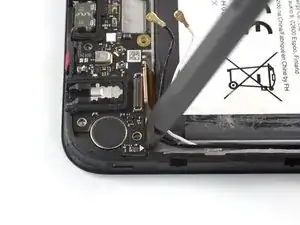
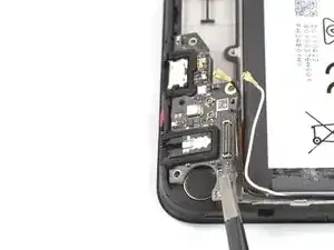
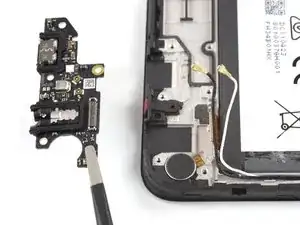
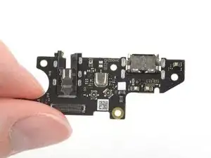
Use this guide to replace the charging port assembly in your Nokia G310 5G.

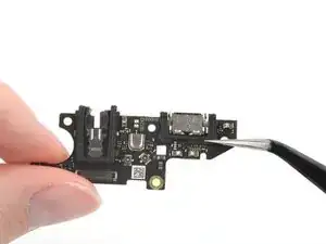
Note: The Nokia G310 5G's charging port assembly is a daughterboard that includes both the USB-C charging port and the headphone jack.

  1. 2gdDZwvEnoSLNEfX
    2gdDZwvEnoSLNEfX
    rc6kEZEhNbFhpGIg
    hS54eEdGWfOfxfvx
    • Power down your phone and unplug any cables.

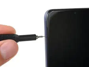
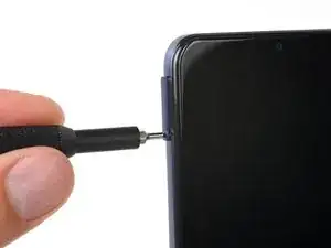
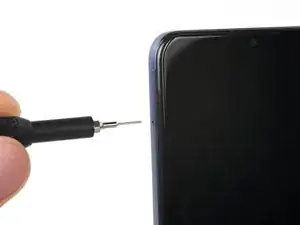
    • Insert a SIM eject tool, bit, or a straightened paper clip into the small hole on the SIM card tray on the upper left edge of the phone.

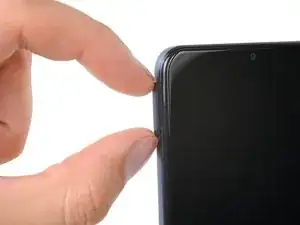
    • Press firmly to eject the tray.

  2. uS1a3KKLK3S1SGmv
    uS1a3KKLK3S1SGmv
    fJbOEOtvDS2V1ls5
    d5smrTZNHCQCZlQp
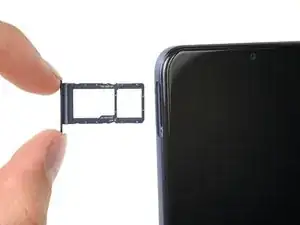
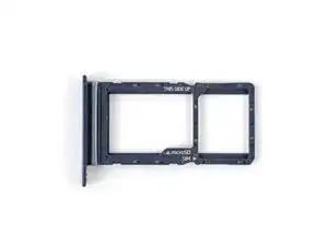
    • Remove the SIM card tray.

    • When installing either a SIM card or a microSD card, make sure they're in the correct orientation and sitting completely flush with the edges of the tray before reinserting the tray into the phone.

  3. 1mD6AEajawgWeXmE
    1mD6AEajawgWeXmE
    phJm5HU6WbWPIFCc
    XM5aElYRbgaxGunQ
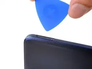
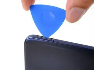
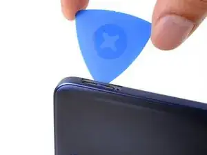
    • The back cover is held in place by plastic clips.

    • Insert an opening pick under the small notch in the SIM card tray slot.

  4. C5fPPEWcYcWSJrYl
    C5fPPEWcYcWSJrYl
    fTuFTTWhtkbPsB5I
    AQIxGoMNE6PR3m2G
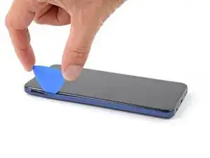
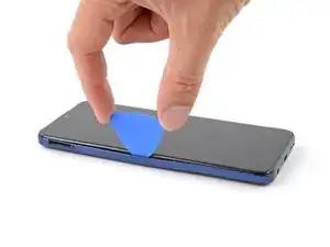
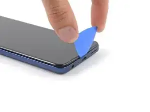
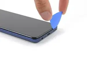
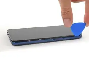
    • Position the opening pick at a steep downward angle between the back cover and the screen assembly.

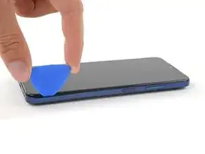
    • Slide the opening pick down the left edge of the phone to release the plastic clips.

  5. xYjuYYKBYhifBx2f
    xYjuYYKBYhifBx2f
    iRFPMdly2FRMGLDG
    TF2vP6yQmPugSBPn
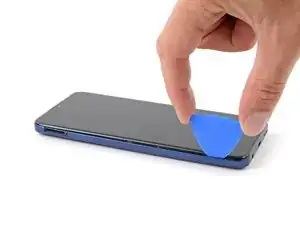
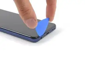
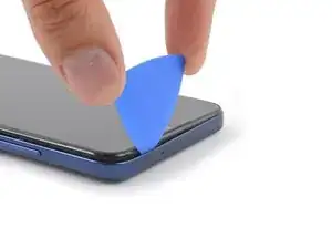
    • Turn the opening pick around the corner and continue to slide it along the bottom edge to release the plastic clips.

  6. edYNbCHTXErtucUV
    edYNbCHTXErtucUV
    vWKSuMGAxBkDsI4I
    TL2VM46x2EU4siBe
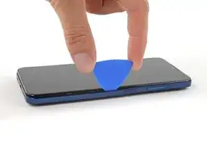
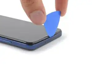
    • Slide the opening pick up the right edge to continue releasing the plastic clips.

  7. wYcYXwraYE33uMfN
    wYcYXwraYE33uMfN
    NTbXENiHqKCpjcXk
    orZWFNSZNYo1XJAl
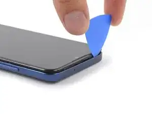
    • Slide the opening pick along the top edge to release the remaining plastic clips.

    • Don't try to fully remove the back cover just yet, as it's still connected with a cable.

  8. YuDWI1yfMY5upJ4C
    YuDWI1yfMY5upJ4C
    DtmsNKJVVmGGZZ2F
    v1uCUiOiwbbFGTSZ
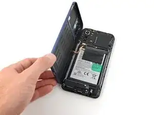
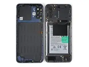
    • With the phone laying screen-side down, carefully lift the right edge of the back cover, opening it like a book.

    • Take care not to strain or tear the attached fingerprint reader cable during this procedure.

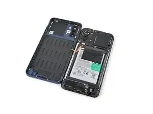
    • Lay the back cover next to the phone.

  9. E6pxGORaJFKFnKhi
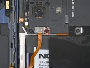
    • Use a Phillips screwdriver to remove the 3.8 mm‑long screw securing the fingerprint reader bracket.

  10. XnpfXQAqqVOjhkTn
    XnpfXQAqqVOjhkTn
    OP3IHr2ygLRRT1yA
    afSWqrK1dIwhgrab
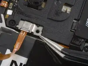
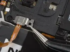
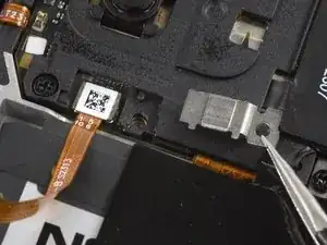
    • Use a pair of tweezers or your fingers to remove the fingerprint reader bracket.

    • Take care not to puncture the battery with sharp tools—a punctured or creased battery may leak dangerous chemicals or cause a fire.

    • During reassembly, make sure to slide the bracket's edge back into its slot under the motherboard cover.

  11. wxsbUP6pYVg2X5Vq
    wxsbUP6pYVg2X5Vq
    WrYCCYnfXPeiEZRX
    IOXSYqTm6mSkPC2n
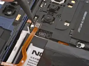
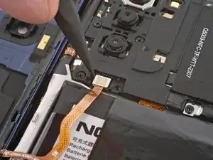
    • Use the pointed end of a spudger to disconnect the fingerprint reader by prying the connector straight up from its socket.

    • To re-attach press connectors like this one, carefully align and press down on one side until it clicks into place, then repeat on the other side. Don't press down on the middle. If the connector is misaligned, the pins can bend and cause permanent damage.

    • Remove the back cover.

  12. N1qWPTJ1UnQUZKvR
    • A white sticker might cover one of the top screws. Pierce through it with the tip of your screwdriver or use a pair of tweezers to remove it.

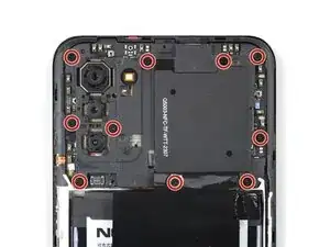
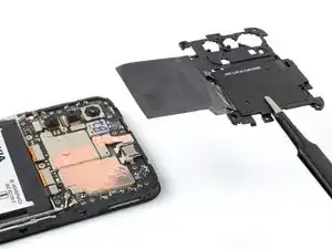
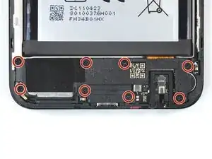
    • Use a Phillips screwdriver to remove the ten 3.8 mm-long screws securing the motherboard cover.

  13. w5IqZQGYTGZo3PUs
    w5IqZQGYTGZo3PUs
    xSOdSpYAEbjbr4ir
    jUUuEG4nSlYdnjb3
    • The motherboard cover is further held in place by plastic clips.

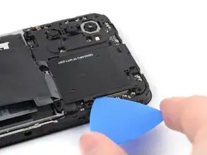
    • Insert an opening pick under the right edge of the motherboard cover.

    • Twist the opening pick to release the plastic clips.

  14. oCPGCYlL2vTt4JSI
    oCPGCYlL2vTt4JSI
    3IBiq3Z3ijgY1B1O
    vKZSWFmArHREskSu
    • Use a pair of tweezers or your fingers to remove the motherboard cover.

  15. FWt4E4QTDY3MotYi
    FWt4E4QTDY3MotYi
    AoghcSaAHaDCK33o
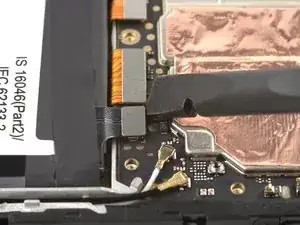
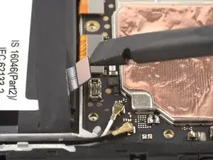
    • Use the flat end of a spudger to disconnect the battery cable by prying the connector straight up from its socket.

  16. 1cVe41XQLnBt2KSQ
  17. 6KSq316WiUu1SYGn
    6KSq316WiUu1SYGn
    Kveh6ZQOlqtUdVKP
    4EhVkKOaUAp4nCfI
    • Insert an opening pick underneath the top right edge of the loudspeaker.

    • Avoid pushing down at a sharp angle, or you risk damaging the interconnect ribbon cable underneath.

    • Twist the opening pick to release loudspeaker from the plastic clips holding it in place.

  18. VGwPxZIXqgSaHlA5
    VGwPxZIXqgSaHlA5
    MBPR4rfLs6CXPNgm
    • Use a pair of tweezers or your fingers to remove the loudspeaker.

  19. dRdYNtM3AcrRVSYb
    dRdYNtM3AcrRVSYb
    VLlGMGr4SsXFXG4r
    • Use the flat end of a spudger to disconnect the interconnect cable by prying the connector straight up from its socket.

  20. dWLMcRUWmp3vrgKm
    dWLMcRUWmp3vrgKm
    V5LRqm4THKEtiZoe
    TbVuLpUYGjvFmQrI
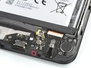
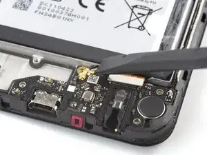
    • Use a spudger to disconnect the antenna cables by prying their coaxial connectors straight up from the sockets on the board.

  21. UrtV1VSarvHQHQvP
    UrtV1VSarvHQHQvP
    VJmurH6IGlh3NxiF
    DcWcVKpLIucGtvkB
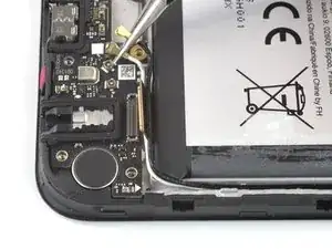
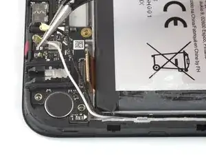
    • Use a pair of tweezers or your fingers to grip the antenna cables near the connectors.

    • Reposition the antenna cables out of the way of the charging port assembly.

  22. lxWyD1ZnCTWKXv4Y
    lxWyD1ZnCTWKXv4Y
    5AFuahVCE3GZlSoZ
    hGaUfPW4D1AbuleZ
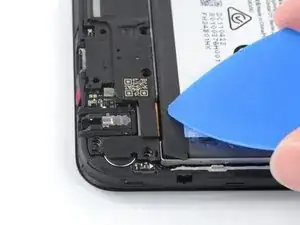
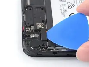
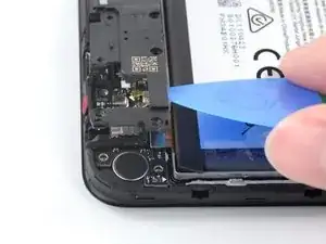
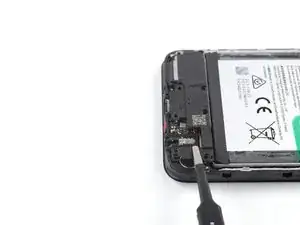
    • The charging port assembly is held in place with mild adhesive.

    • Insert the flat end of a spudger underneath the top right edge of the charging port assembly.

    • Pivot the charging port assembly up until you can grip it with your fingers.

  23. 2JVKjX4enhvYILKn
    2JVKjX4enhvYILKn
    A3hVTCBjixsulTII
    • Use your fingers or a pair of tweezers to remove the charging port assembly.

  24. ELZXWuQQeAGRMJDT
    ELZXWuQQeAGRMJDT
    vRIGtj2MYvVgfSHb
    SCBbJnRWhLmUUCIt
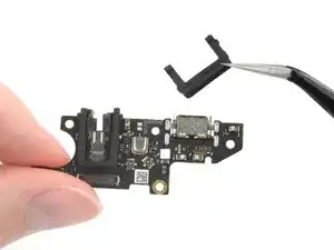
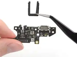
    • Use a pair of tweezers to remove the two black U-shaped rubber gaskets from the charging port and the headphone jack.

    • Only the charging port assembly remains.

    • During reassembly, transfer the rubber gaskets to the replacement board before securing it back into the frame.

Conclusion

To reassemble your device, follow these instructions in reverse order.

Take your e-waste to an R2 or e-Stewards certified recycler.

Repair didn’t go as planned? Try some basic troubleshooting, or ask our Answers community for help.
Clay Eickemeyer

Member since: 19/09/22

65190 Reputation

0 comments