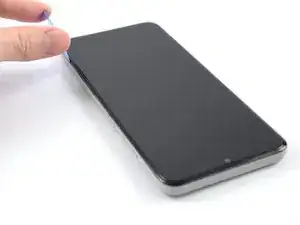
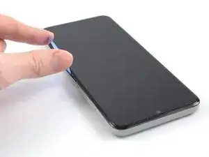
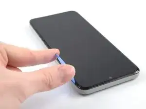
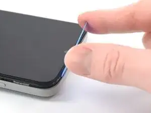
Introduction
This is a prerequisite-only guide! This guide is part of another procedure and is not meant to be used alone.
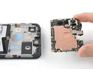
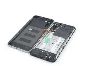
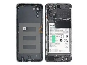
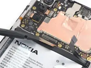
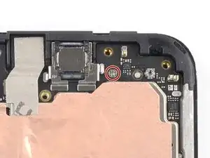
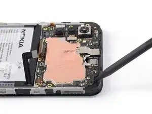
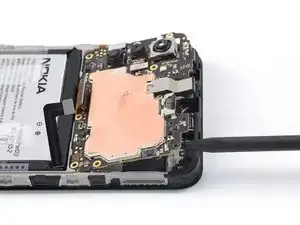
Use this guide to remove the motherboard in the Nokia G22.
Tools
-
-
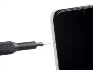
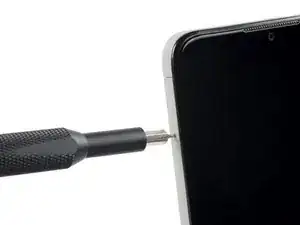
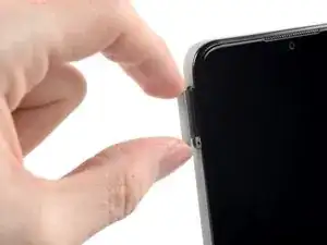
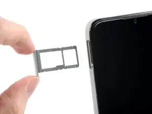
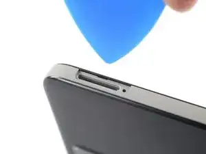
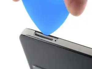
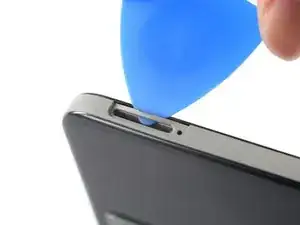
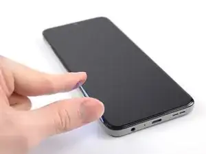
Insert a SIM eject tool, bit, or a straightened paper clip into the small hole on the SIM card tray on the upper left edge of the phone.
-
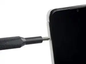
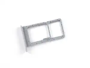
Press firmly to eject the tray.
-
-
-
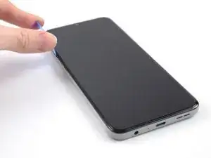
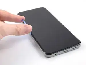
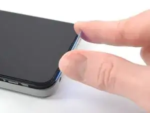
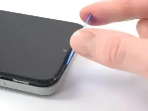
Position the opening pick at a steep downward angle between the back cover and the screen assembly.
-
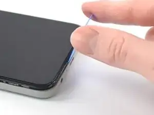
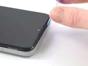
Slide the opening pick down the left edge of the phone to release the plastic clips.
-
-
-
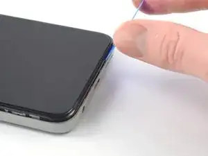
Turn the opening pick around the corner and continue to slide it along the bottom edge to release the plastic clips.
-
-
-
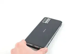
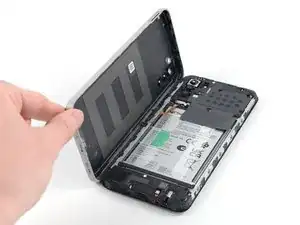
With the phone laying screen-side down, carefully lift the right edge of the back cover, opening it like a book.
-
Lay the back cover next to the phone.
-
-
-
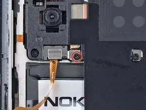
Use a Phillips screwdriver to remove the 3.8 mm‑long screw securing the fingerprint reader bracket.
-
-
-
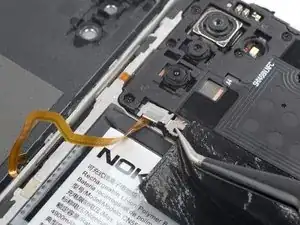
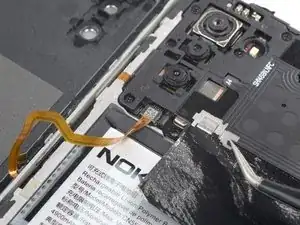
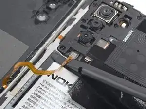
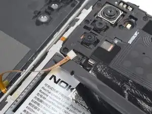
Use the flat end of a spudger to disconnect the fingerprint reader by prying the connector straight up from its socket.
-
Remove the back cover.
-
-
-
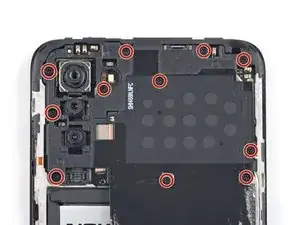
Use a Phillips screwdriver to remove the eleven 3.8 mm-long screws securing the motherboard cover.
-
-
-
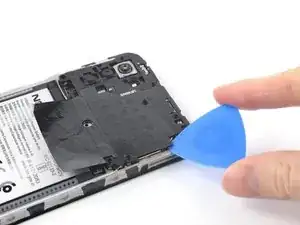
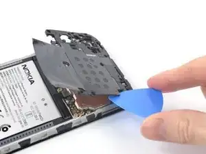
Insert an opening pick under the right edge of the motherboard cover to release its plastic clips.
-
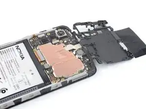
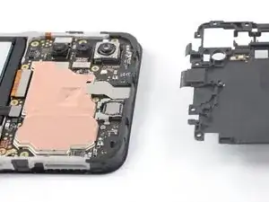
Flip the motherboard cover over the top edge of the phone.
-
-
-
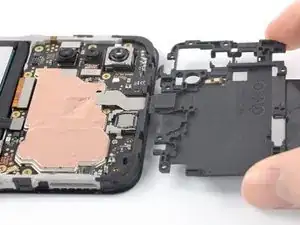
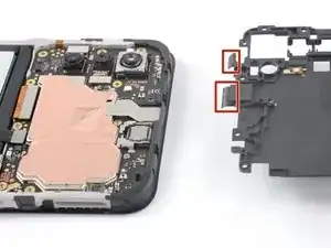
The motherboard cover has two short adhesive tapes wrapped around the top edge and onto the frame.
-
Pull the motherboard cover away from the frame to separate the adhesive tape and remove it.
-
-
-
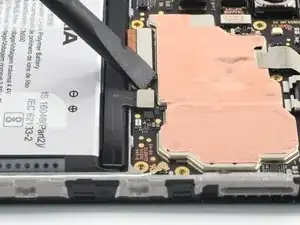
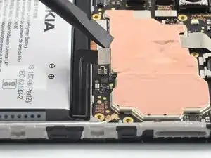
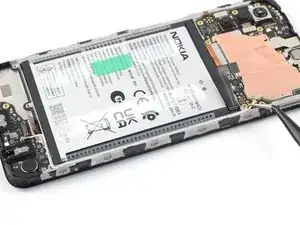
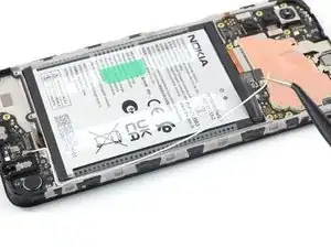
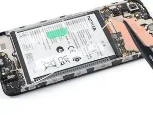
Use the flat end of a spudger to disconnect the battery cable by prying the connector straight up from its socket.
-
-
-
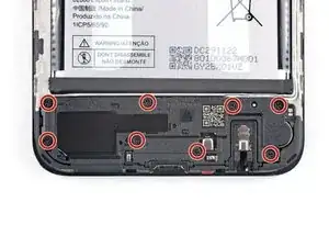
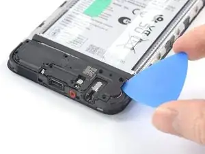
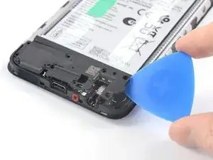
Insert an opening pick underneath the right edge of the loudspeaker.
-
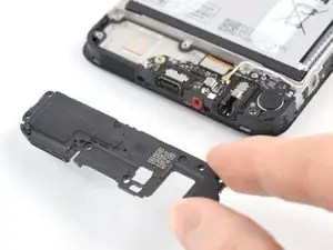
Twist the opening pick to release loudspeaker from the plastic clips holding it in place.
-
-
-
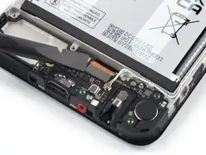
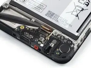
Use the flat end of a spudger to disconnect the display cable by prying the connector straight up from its socket.
-
-
-
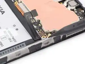
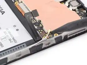
Use the pointed end of a spudger to disconnect the antenna cable by prying the connector straight up from its socket on the motherboard.
-
-
-
Use a pair of tweezers or your fingers to lift the antenna cable out of its recess in the frame.
-
-
-
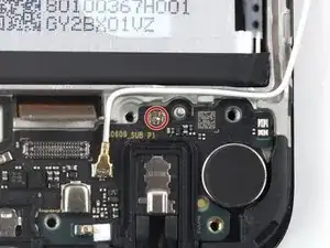
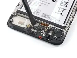
Use a Phillips screwdriver to remove the 2.8 mm‑long screw securing the charging port assembly.
-
-
-
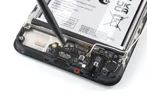
Insert the flat end of a spudger underneath the top edge of the charging port assembly.
-
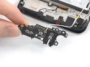
Pry up the charging port assembly by twisting the spudger until you can grip it with your fingers.
-
-
-
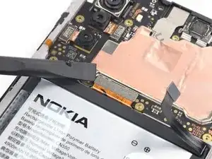
Use the flat end of a spudger to disconnect the display cable by prying the connector up from its socket.
-
-
-
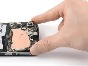
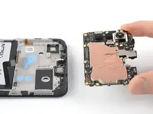
Insert the pointed end of a spudger underneath the top right corner of the motherboard.
-
Pry the motherboard up until you can grip it with your fingers.
-
To reassemble your device, follow these instructions in reverse order.
Take your e-waste to an R2 or e-Stewards certified recycler.
Repair didn’t go as planned? Try some basic troubleshooting, or ask our Answers community for help.
