Introduction
This guide is a prerequisite to removing the earpiece.
Tools
-
-
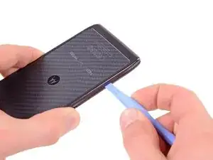
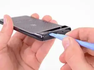
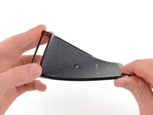
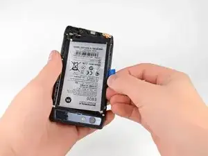
Insert a plastic opening tool between the back cover and rear case at the lower left edge of the back cover.
-
Pry the back cover up with the plastic opening tool to free the plastic clips.
-
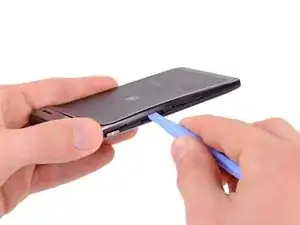
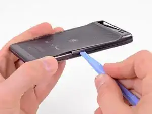
Continue prying along the left edge of the back cover towards the top of the phone.
-
-
-
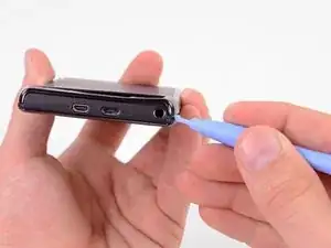
Work the plastic opening tool across the top of the back case to free the plastic clips.
-
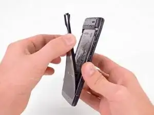
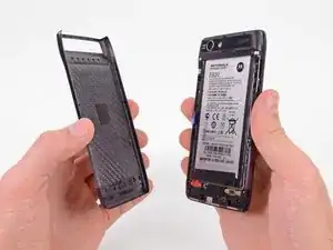
Continue prying down the right side of the back cover to free the remaining clips.
-
-
-
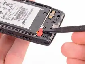
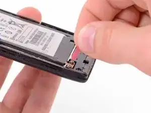
Use the tip of a spudger to lift up the red silicone cover over the battery terminal screws and remove it.
-
-
-
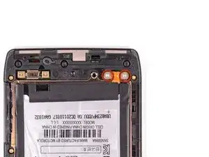
Remove the two 3.3 mm T5 Torx battery terminal screws.
-
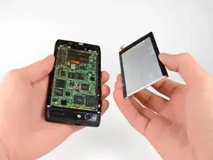
Grab the blue battery removal tab and lift the battery out to remove it.
-
-
-
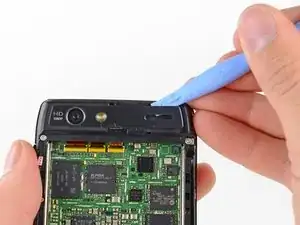
Use a heat gun or hair dryer to soften the adhesive underneath the camera cover.
-
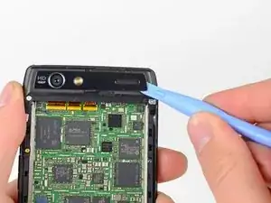
Gently pry up the bottom edge of the camera cover with a plastic opening tool.
-
Carefully slide the plastic opening tool across the bottom edge to free it from the adhesive.
-
Continue to use the heat gun as needed to soften the adhesive as you remove the camera cover.
-
-
-
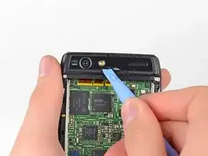
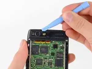
Insert the plastic opening tool underneath the top edge of the camera cover.
-
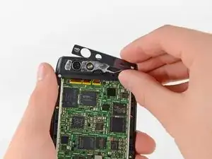
Gently pry the camera cover up as you slide the plastic opening tool across the top edge to free it from the adhesive.
-
Remove the camera cover.
-
-
-
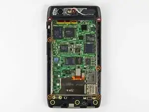
Remove the six screws securing the rear case to the rest of the phone:
-
three 6.7 mm silver T3 Torx screws at the top,
-
four 4.0 mm gold T3 Torx screws in the middle,
-
and three 4.5 mm black T5 Torx screws at the bottom.
-
-
-
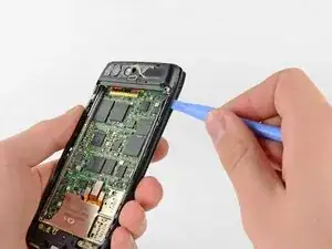
Insert a plastic opening tool between the rear case and the motherboard assembly.
-
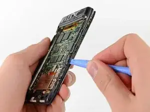
Work your way down the side of the phone and gently pry the rear case up.
-
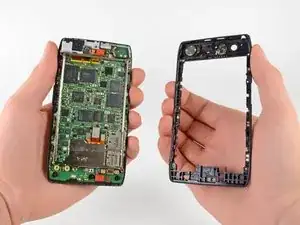
Separate the rear case from the motherboard assembly.
-
-
-
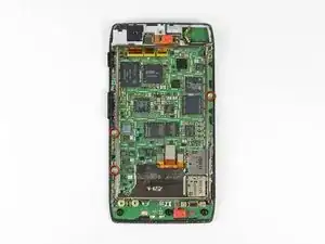
Remove the three 2.5 mm T3 Torx screws securing the metal chassis to the motherboard.
-
Remove the metal chassis from the motherboard assembly.
-
-
-
Use the flat end of a spudger to remove the two red silicone microphone covers at the top and bottom of the motherboard.
-
-
-
Use the flat end of a spudger to pry the three display cable connectors off their sockets on the motherboard.
-
-
-
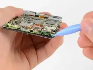
Use a heat gun or hair dryer to soften the adhesive strip around the perimeter of the motherboard.
-
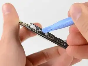
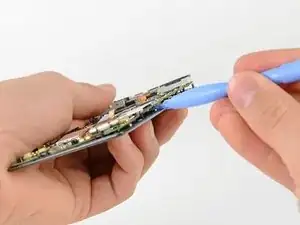
Pry the edges of the motherboard up from the display assembly with a plastic opening tool.
-
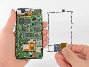
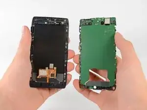
Remove the motherboard assembly.
-
-
-
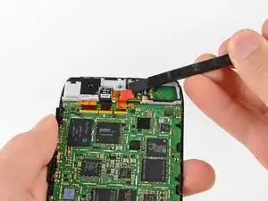
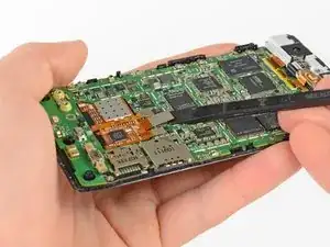
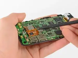
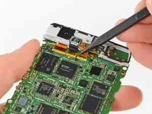
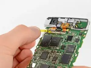
Lift up the anti-static tape covering the camera and earpiece ZIF connectors with the tip of a spudger.
-
Peel back the tape and remove it.
-
-
-
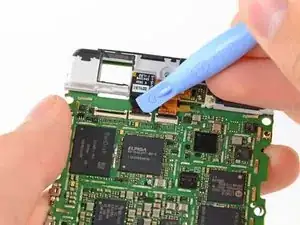
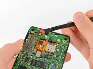
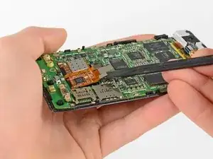
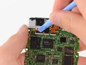
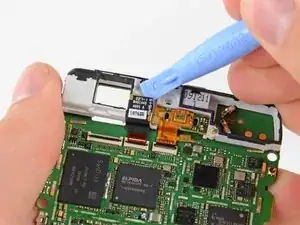
Use a plastic opening tool or your fingernail to lift up the tab on the rear-facing camera ribbon cable ZIF connector.
-
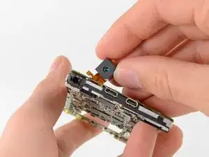
Push the rear-facing camera through its hole in the grey antenna and remove it.
-
-
-
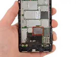
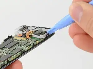
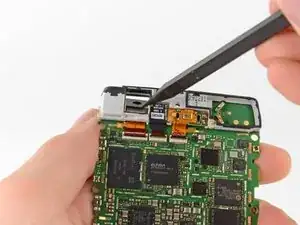
Use a plastic opening tool or your fingernail to lift up the tab on the front-facing camera ribbon cable ZIF connector.
-
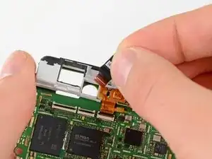
Lift the front-facing camera out of the antenna with the plastic opening tool and remove it.
-
To reassemble your device, follow these instructions in reverse order.
